EP1700517A1 - Pflug - Google Patents
Pflug Download PDFInfo
- Publication number
- EP1700517A1 EP1700517A1 EP06110586A EP06110586A EP1700517A1 EP 1700517 A1 EP1700517 A1 EP 1700517A1 EP 06110586 A EP06110586 A EP 06110586A EP 06110586 A EP06110586 A EP 06110586A EP 1700517 A1 EP1700517 A1 EP 1700517A1
- Authority
- EP
- European Patent Office
- Prior art keywords
- plow
- age
- bolt
- frame
- articulation
- Prior art date
- Legal status (The legal status is an assumption and is not a legal conclusion. Google has not performed a legal analysis and makes no representation as to the accuracy of the status listed.)
- Granted
Links
- 230000002441 reversible effect Effects 0.000 claims description 5
- 239000004575 stone Substances 0.000 abstract description 3
- 239000002689 soil Substances 0.000 abstract description 2
- NRTLIYOWLVMQBO-UHFFFAOYSA-N 5-chloro-1,3-dimethyl-N-(1,1,3-trimethyl-1,3-dihydro-2-benzofuran-4-yl)pyrazole-4-carboxamide Chemical compound C=12C(C)OC(C)(C)C2=CC=CC=1NC(=O)C=1C(C)=NN(C)C=1Cl NRTLIYOWLVMQBO-UHFFFAOYSA-N 0.000 description 4
- 238000010276 construction Methods 0.000 description 3
- 230000006866 deterioration Effects 0.000 description 3
- 230000000694 effects Effects 0.000 description 3
- 230000001960 triggered effect Effects 0.000 description 3
- 238000005516 engineering process Methods 0.000 description 2
- 238000012423 maintenance Methods 0.000 description 2
- 238000010008 shearing Methods 0.000 description 2
- 244000261422 Lysimachia clethroides Species 0.000 description 1
- 230000002159 abnormal effect Effects 0.000 description 1
- 230000009471 action Effects 0.000 description 1
- 238000005452 bending Methods 0.000 description 1
- 230000000903 blocking effect Effects 0.000 description 1
- 230000008859 change Effects 0.000 description 1
- 230000008878 coupling Effects 0.000 description 1
- 238000010168 coupling process Methods 0.000 description 1
- 238000005859 coupling reaction Methods 0.000 description 1
- 238000013016 damping Methods 0.000 description 1
- 230000001419 dependent effect Effects 0.000 description 1
- 230000008034 disappearance Effects 0.000 description 1
- 238000006073 displacement reaction Methods 0.000 description 1
- 230000005489 elastic deformation Effects 0.000 description 1
- 238000002513 implantation Methods 0.000 description 1
- 230000004048 modification Effects 0.000 description 1
- 238000012986 modification Methods 0.000 description 1
- 239000007787 solid Substances 0.000 description 1
- 238000006467 substitution reaction Methods 0.000 description 1
Images


Classifications
-
- A—HUMAN NECESSITIES
- A01—AGRICULTURE; FORESTRY; ANIMAL HUSBANDRY; HUNTING; TRAPPING; FISHING
- A01B—SOIL WORKING IN AGRICULTURE OR FORESTRY; PARTS, DETAILS, OR ACCESSORIES OF AGRICULTURAL MACHINES OR IMPLEMENTS, IN GENERAL
- A01B61/00—Devices for, or parts of, agricultural machines or implements for preventing overstrain
- A01B61/04—Devices for, or parts of, agricultural machines or implements for preventing overstrain of the connection between tools and carrier beam or frame
- A01B61/042—Devices for, or parts of, agricultural machines or implements for preventing overstrain of the connection between tools and carrier beam or frame with shearing devices
Definitions
- the present invention relates to the general technical field of agricultural machinery. It relates more particularly to a plow comprising a front end and a rear end comprising a frame and at least one age each age is connected to said frame by means of a first articulation of substantially horizontal axis and perpendicular to the direction of advance and carries directly or indirectly at least one plow body, said age is also equipped with at least one safety device for retracting the plow body backwards when encountering an obstacle buried in the ground.
- a non-stop hydraulic safety comprises a jack and a damping element consisting of a pressure accumulator. This oleopneumatic technology uses a variety of components that weigh down the weight and cost of the plow.
- FR 1 458 614 refers to a shear bolt safety device for a plow age.
- the age is linked to the frame by means of a first articulation of substantially horizontal axis and substantially orthogonal to the direction of movement during work.
- the shear bolt crosses the age and the frame from one side to the other, thus blocking the pivoting of the age around the first pivot joint as long as the plow body does not meet an abnormal resistance.
- the safety bolt is intended to break as soon as the plow body is subjected to an excessive force generated by an obstacle.
- the first hinge allows the age to pivot backwards and upwards as soon as the safety bolt breaks.
- the bolt is sheared.
- the triggering of this safety device respectively the shearing of the bolt becomes random.
- the bolt tends to deform under the effect of a shearing force.
- There is also a matting of adjacent parts of the shear bolt which causes on the one hand a less accurate break and on the other hand a painful disassembly of parts of the sheared bolt. It is, indeed, common that the two parts of the sheared bolt are stuck in their homes. Thus, the release of the parts of the bolt is relatively difficult and the replacement of the bolt is therefore rather long.
- the document FR 1138 538 describes a safety device using a tension-biased bolt for a plow strut.
- the prop is attached to the plow-age spar by means of a hinge. This articulation allows the stanchion to rotate around the age.
- the pivoting of the strut relative to the age is secured by the traction bolt which keeps the stanchion in a position substantially vertical with respect to age.
- the traction bolt breaks, due to excessive force at the tip of the ploughshare, the plow body with its respective prop retracts by pivoting backwards in view of the direction of advance.
- the object of the present invention is to overcome the disadvantages of known safety devices while ensuring a simple, reliable and inexpensive embodiment.
- said plow is characterized in that at least one of said ages comprises a safety device produced in the form of a bolt biased to traction.
- the triggering of the safety device is accurate when the force at the tip of the plow body exceeds the allowable value.
- the breakage of the bolt by pulling is straightforward, the release operation of the parts of the broken bolt is easy and the replacement of the bolt is fast.
- said first articulation is arranged in front of the plummet point in view of the direction of advance. This particular implantation of the first articulation allows the body of plowing and the respective age to be raised in front of the obstacle by its rotational movement around the first joint when the tension bolt breaks. The plow body is thus immediately disengaged from the ground during the breaking of the traction bolt.
- the machine according to the invention is a mounted plow (1).
- said plow (1) consists of a front end (2) and a rear end (3).
- the limber (2) is the front part of the plow (1) which is connected to the three-point hitch system (4) of a tractor (5).
- the limber (2) is still intended to carry the rear end (3) of the plow (1).
- the rear end (3) is generally composed of a frame (6), at least one age (7) and at least one plow body (8).
- the frame (6) consists of a square or rectangular section beam which is reinforced locally to withstand twisting forces during work and bending stresses during transport.
- This frame structure (6) allows him, among other things, to support plow ages (7).
- the plow (1) has three ages (7) each equipped with two plowing body (8).
- Each age (7) is connected to the frame (6) by means of a first articulation (9).
- This first hinge (9) has an axis at least substantially horizontal and at least substantially orthogonal to the direction (A) of displacement during work.
- Each age (7) supports at least one plow body (8) by means of a corresponding stanchion (10).
- the age (7) serves to transmit the traction force of the tractor (5) to the plow body (8).
- the latter comprises a share (11) which cuts a strip of soil which is then returned by a moldboard (12) during the movement of the plow (1) in the direction of advance (A).
- Said plow (1) is moved in a direction and a direction of advance indicated by the arrow (A).
- the notions "before” and “backward”, “before” and “behind” are defined with respect to the direction of advance (A) and the notions “right” and “left” are defined by looking at said plow (1) from the rear in said direction of advance (A).
- the mounted plow (1) is a plow (1) of the reversible type.
- the plow (1) thus comprises two groups (8A; 8B) of plow body (8).
- the plow (1) is also equipped with a turning device (13) carried by the front end (2).
- the turning device makes it possible to pivot the rear end (3) about 180 ° around a turning axis, the plow (1) can therefore occupy at least two working positions.
- the frame (6) is connected to the forehearth (2) by means of the turning axis which is also called the rocket.
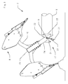
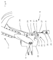
- FIG 2 shows an age (7) to be mounted on a reversible plow (1) in a working position.
- the age (7) supports two plowing bodies (8) by means of a respective stanchion (10).
- One of the plow bodies (8) belongs to the first group (8A) and the other belongs to the second group (8B).
- the age (7) consists of a spar (15) and two struts (10) each carrying a plow body (8).
- the spar (15) is a substantially horizontal longitudinal element while the strut (10) is a substantially vertical piece having for example a gooseneck shape.
- the struts (10) are connected on either side of the spar (15).
- the spar (15) is connected to said frame (6) by means of the first articulation (9).
- the age (7) is formed of a single piece comprising a spar (15) and two struts (10).
- the plow bodies (8) of the plow (1) are intended to work in the ground, they can meet significant obstacles such as stones.
- said age (7) is equipped with at least one safety device (16). It allows the retraction of the plow body (8) backwards when it encounters an obstacle buried in the ground.
- the purpose of this safety device (16) is to erase the body (8) when the stresses at the tip of the plow (11) are capable of causing damage to the plow (1).
- the safety device (16) is triggered for allowable stresses, lower than those causing deterioration of the age (7) or the frame (6).
- At least one of said ages (7) comprises a safety device (16) in the form of a bolt (17) biased to traction.
- a safety device (16) in the form of a bolt (17) biased to traction.
- each of the three ages (7) of the plow (1) is equipped with a safety device (16) in the form of a bolt (17) biased to traction .
- a safety device (16) in the form of a bolt (17) biased to traction .
- the plows often include several plowing bodies (8) arranged one behind the other.
- the plow (1) of Figure 1 has two groups of three plowing bodies (8A, 8B).
- Each of the three plowing bodies (8) is used during work, each plow body (8) is therefore likely to encounter an obstacle such as a stone likely to damage the plow (1).
- each age (7) is equipped with a safety device (16) in the form of bolt (17) breaking working traction.
- the safety device (16) must be effective even with increasing efforts and plowing speeds.
- the role of this safety device (16) is to prevent the deformation or breakage of an essential part of the plow (1) during an impact with an obstacle.
- the traction bolt (17) extends substantially perpendicular to the axis of the first articulation (9) for an optimal efficiency of the safety device (16).
- the traction bolt (17) is, in the embodiment shown in Figure 2, substantially vertical.
- the traction bolt (17) is advantageously formed by a screw (18), a nut (19) and a counter nut (20).
- said first hinge (9) is arranged at least in the vertical plane containing the hinge point (11) taking into account the direction of advance (A).
- said first articulation (9) is arranged in front of the tip of soc (11).
- the vertical plane containing said first hinge (9) of an age (7) is disposed clearly in front of the vertical plane containing the tip of the ploughshare (11) of the corresponding plow body (8).
- This position of the first hinge (9) relative to the plow tip (11) allows when breaking the traction bolt (17) to clear the share (11) in front of the obstacle.
- the plow body (8) is thus directly raised off the ground in front of the obstacle as shown in Figure 3. It is therefore a safety device (16) releasing.
- the beam (15) of the age (7) is held in position on the frame by at least one plate (21) by means of the traction bolt (17).
- the pivoting of the age (7) around the first articulation (9) is thereby prevented.
- the spar (15) is substantially parallel to the frame (6) of the plow (1).
- the traction bolt (17) is associated with two plates (21). Each plate (21) carries a stop for the age (7) in one of the two working positions.
- the beam (15) is clamped between the two plates (21) by the traction bolt (17).
- the screw (18) could lengthen until breaking.
- the age (7) will then be able to vote, backwards and upwards, around the axis of the first articulation (9) as shown in FIG. 3.
- the age (7) can thus be erased. and no rupture of the plow body (8), the age (7) or even the frame (6) is to be feared.
- the plow (1) is again operational for the rest of the work.
- FIG. 2 and 3 it is a plow (1) with variable working width.
- the age (7) is thus connected to the frame (6) by means of a housing (22).
- the housing (22) is connected to the frame (6) of the plow (1) by a second articulation (23) of substantially vertical axis.
- This second articulation (23) makes it possible to adapt the plow body (8) to different cutting widths.
- the housing (22) is connected to the age (7) by means of said first articulation (9).
- the end of the age (7) has a clevis (24) which allows the age (7) to pivot relative to the housing (22) around the first joint (9).
- the housing (22) has a recess (25) in the rear in a substantially vertical direction.
- each age (7) is secured by two traction bolts (17).
- One of the traction bolts (17) is active in one of the working positions and the other traction bolt (17) is active in the other working position.
- the spar (15) of the age (7) is held between the two plates (21) by the two bolts (17).
- the lower plowing body (8) under the frame (6), is in a working configuration, it is engaged in the ground. It is secured by the upper traction bolt (17) which is intended to break if the force at the tip of the share (11) is too high.
- each pull bolt (17) is preferably associated with a wafer (21).
- Said plate (21) allows to place the beam (15) relative to said frame (6).
- the clearance (25) in the rear part of the housing (22) advantageously accommodates the two traction bolts (17).
- the clearance (25) allows on the one hand to thread said bolts (17) and on the other hand to hold them to tighten the plate (21) against the corresponding housing (22).
- the age (7) equipped with two plowing bodies (8) is held by a single traction bolt (17).
- the spar (15) is clamped between two plates (21) by a single screw (18) which passes through the housing (22).
- the bolt (17) breaks, its replacement is delicate and often long because the age (7) is often positioned below the position to put a screw (18). So first reposition the age (7) and in particular the spar (15) in the extension of the frame (6) or the case of the housing (22) so as to thread the screw (18).
- the housing (22) comprises, for each working position, a high stop (26).
- This high stop (26) avoids damaging the environment close to the age (7) which triggered with the breaking of the traction bolt (17).
- each plate (21) is held by a device (27).
- the device (27) retains the plate (21) and prevents the plate (21) from being lost in the earth.
- This device (27) is preferably attached to the age (7) of the plow (1).
- this device (27) is a flexible link. To avoid losing the part of the bolt with the nut (19) and the lock nut (20) during a break, it is connected to the plate (21) by a fastener (28).
- This fastener (28) is advantageously mounted between the nut (19) and the counter nut (20).
- said plow is of the simple non-reversible type.
- each age carries only one plow body and the safety device has only one pulling bolt.
- said plow is of the fixed working width type.
- the age is thus directly related to said frame via the first articulation.
- This invention also applies to plows with multiple working widths.
- said plow is of the semi-mounted type.
- the rear end is provided with wheels by means of which said plow rests at least partially on the ground.
- the present invention also relates to trailed type plows.
- the coupling of the plow to the tractor is done simply by a drawbar hanging on the peak.
Landscapes
- Life Sciences & Earth Sciences (AREA)
- Engineering & Computer Science (AREA)
- Mechanical Engineering (AREA)
- Soil Sciences (AREA)
- Environmental Sciences (AREA)
- Soil Working Implements (AREA)
Applications Claiming Priority (1)
| Application Number | Priority Date | Filing Date | Title |
|---|---|---|---|
| FR0550598A FR2882619B1 (fr) | 2005-03-07 | 2005-03-07 | Charrue comportant un dispositif de securite a boulon de traction |
Publications (2)
| Publication Number | Publication Date |
|---|---|
| EP1700517A1 true EP1700517A1 (de) | 2006-09-13 |
| EP1700517B1 EP1700517B1 (de) | 2008-10-22 |
Family
ID=35395965
Family Applications (1)
| Application Number | Title | Priority Date | Filing Date |
|---|---|---|---|
| EP20060110586 Expired - Lifetime EP1700517B1 (de) | 2005-03-07 | 2006-03-02 | Pflug |
Country Status (3)
| Country | Link |
|---|---|
| EP (1) | EP1700517B1 (de) |
| DE (1) | DE602006003243D1 (de) |
| FR (1) | FR2882619B1 (de) |
Cited By (3)
| Publication number | Priority date | Publication date | Assignee | Title |
|---|---|---|---|---|
| WO2014006575A3 (en) * | 2012-07-04 | 2014-03-06 | Lohar Shrikrishna Shamrao | Systems and methods for ploughing |
| CN115606337A (zh) * | 2022-11-04 | 2023-01-17 | 新疆农垦科学院 | 一种犁耕机械防过载自动避障机构 |
| EP4458122A1 (de) * | 2023-05-05 | 2024-11-06 | CNH Industrial Sweden AB | Drehpflug |
Families Citing this family (1)
| Publication number | Priority date | Publication date | Assignee | Title |
|---|---|---|---|---|
| WO2020012513A1 (en) * | 2018-07-10 | 2020-01-16 | Moro Aratri S.R.L. | Digging plough |
Citations (6)
| Publication number | Priority date | Publication date | Assignee | Title |
|---|---|---|---|---|
| CH89491A (de) * | 1917-04-19 | 1921-06-01 | Ott Geb | Anordnung von Pflugkörpern an Pflügen. |
| US2612827A (en) * | 1948-12-09 | 1952-10-07 | Sperry Corp | Releasable implement connection |
| FR1113280A (fr) * | 1954-05-03 | 1956-03-26 | Charrue articulée | |
| FR1138538A (fr) | 1955-12-12 | 1957-06-14 | Dispositif de montage d'un corps de charrue sur un age | |
| FR1458614A (fr) | 1965-09-29 | 1966-03-04 | Fenet Sa Des Ets | Charrue |
| DE3146920A1 (de) * | 1981-10-22 | 1983-06-01 | Ernst 7326 Heiningen Weichel | Steinsicherung fuer die arbeitswerkzeuge von schichtengrubbern |
-
2005
- 2005-03-07 FR FR0550598A patent/FR2882619B1/fr not_active Expired - Fee Related
-
2006
- 2006-03-02 EP EP20060110586 patent/EP1700517B1/de not_active Expired - Lifetime
- 2006-03-02 DE DE200660003243 patent/DE602006003243D1/de not_active Expired - Lifetime
Patent Citations (6)
| Publication number | Priority date | Publication date | Assignee | Title |
|---|---|---|---|---|
| CH89491A (de) * | 1917-04-19 | 1921-06-01 | Ott Geb | Anordnung von Pflugkörpern an Pflügen. |
| US2612827A (en) * | 1948-12-09 | 1952-10-07 | Sperry Corp | Releasable implement connection |
| FR1113280A (fr) * | 1954-05-03 | 1956-03-26 | Charrue articulée | |
| FR1138538A (fr) | 1955-12-12 | 1957-06-14 | Dispositif de montage d'un corps de charrue sur un age | |
| FR1458614A (fr) | 1965-09-29 | 1966-03-04 | Fenet Sa Des Ets | Charrue |
| DE3146920A1 (de) * | 1981-10-22 | 1983-06-01 | Ernst 7326 Heiningen Weichel | Steinsicherung fuer die arbeitswerkzeuge von schichtengrubbern |
Cited By (4)
| Publication number | Priority date | Publication date | Assignee | Title |
|---|---|---|---|---|
| WO2014006575A3 (en) * | 2012-07-04 | 2014-03-06 | Lohar Shrikrishna Shamrao | Systems and methods for ploughing |
| CN115606337A (zh) * | 2022-11-04 | 2023-01-17 | 新疆农垦科学院 | 一种犁耕机械防过载自动避障机构 |
| CN115606337B (zh) * | 2022-11-04 | 2026-04-17 | 新疆农垦科学院 | 一种犁耕机械防过载自动避障机构 |
| EP4458122A1 (de) * | 2023-05-05 | 2024-11-06 | CNH Industrial Sweden AB | Drehpflug |
Also Published As
| Publication number | Publication date |
|---|---|
| FR2882619B1 (fr) | 2008-08-08 |
| DE602006003243D1 (de) | 2008-12-04 |
| EP1700517B1 (de) | 2008-10-22 |
| FR2882619A1 (fr) | 2006-09-08 |
Similar Documents
| Publication | Publication Date | Title |
|---|---|---|
| EP0679327B1 (de) | Mähmaschine mit einer Sicherheitsvorrichtung | |
| EP3713391B1 (de) | Landwirtschaftliche maschine mit einem vereinfachten sicherheitssystem, das es einem werkzeug oder einer gruppe von werkzeugen, die durch einen tragarm mit einem anhängebock verbunden sind, ermöglicht, eine sicherheitsbewegung auszuführen | |
| EP1700517B1 (de) | Pflug | |
| EP0910940B1 (de) | Landwirtschaftmaschine | |
| EP2158798B1 (de) | Anbaupflug mit verbesserter Stützradaufhängung | |
| FR2964292A1 (fr) | Charrue avec un dispositif pour soulever au moins un age | |
| EP1522218B1 (de) | Sicherheitsvorrichtung für ein Spritzgestängerohr | |
| EP3713390B1 (de) | Landwirtschaftliche maschine mit einem sicherheitssystem mit verbesserter auslösekinematik | |
| EP4147547B1 (de) | Drehpflug mit einem blockiersystem für ein kombi rad | |
| EP2484194B1 (de) | Bodenbearbeitungsmaschine mit einem verbesserten Tragrahmen | |
| EP0448442B1 (de) | Verbesserung an Drehpflügen, mit einer an jedem Halbkörper angeordneten Sicherung gegen Steine und Überlastung | |
| EP1466516B1 (de) | Landwirtschaftliche Maschine mit zumindest einem Rad | |
| EP1133429B1 (de) | Hebezeug am vorderseite einem raupenschlepper und damit ausgerüsteten rupenschlepper | |
| BE1007182A3 (fr) | Patin d'epandage de lisier ou autres engrais. | |
| FR2730598A1 (fr) | Machine agricole de travail du sol avec dispositif de reglage et de securite des ensembles soc/bras de soc | |
| EP1661443B1 (de) | Maschine mit einer Anschlußvorrichtung am Dreipunkt Kupplungssystem eines Traktors | |
| FR2593992A1 (fr) | Dispositif de securite pour charrues. | |
| EP0439408B1 (de) | Vorrichtung zum Ernten von Rüben oder Knollen | |
| FR2763471A1 (fr) | Dechaumeur avec securite d'effacement | |
| BE514720A (de) | ||
| EP0087334A1 (de) | Überlast-Sicherheitseinrichtung für Pflüge | |
| FR2720217A1 (fr) | Dispositif de sécurité à retardement pour charrue non-stop. | |
| FR3041861A1 (fr) | Dispositif ajustable pivotant de porte-outil agricole rotatif pour le travail des sols entre rangs de plantations | |
| FR2778310A1 (fr) | Equipement aratoire pour charrue reversible | |
| WO2009127945A1 (fr) | Vehicule agricole |
Legal Events
| Date | Code | Title | Description |
|---|---|---|---|
| PUAI | Public reference made under article 153(3) epc to a published international application that has entered the european phase |
Free format text: ORIGINAL CODE: 0009012 |
|
| AK | Designated contracting states |
Kind code of ref document: A1 Designated state(s): AT BE BG CH CY CZ DE DK EE ES FI FR GB GR HU IE IS IT LI LT LU LV MC NL PL PT RO SE SI SK TR |
|
| AX | Request for extension of the european patent |
Extension state: AL BA HR MK YU |
|
| 17P | Request for examination filed |
Effective date: 20070301 |
|
| 17Q | First examination report despatched |
Effective date: 20070403 |
|
| AKX | Designation fees paid |
Designated state(s): DE FR GB HU IT |
|
| RBV | Designated contracting states (corrected) |
Designated state(s): AT BE BG CH CY CZ DE DK EE ES FI FR GB GR HU IE IS IT LI LT LU LV MC NL PL PT RO SE SI SK TR |
|
| RBV | Designated contracting states (corrected) |
Designated state(s): DE FR GB HU IT |
|
| GRAP | Despatch of communication of intention to grant a patent |
Free format text: ORIGINAL CODE: EPIDOSNIGR1 |
|
| GRAS | Grant fee paid |
Free format text: ORIGINAL CODE: EPIDOSNIGR3 |
|
| GRAA | (expected) grant |
Free format text: ORIGINAL CODE: 0009210 |
|
| AK | Designated contracting states |
Kind code of ref document: B1 Designated state(s): DE FR GB HU IT |
|
| REG | Reference to a national code |
Ref country code: GB Ref legal event code: FG4D Free format text: NOT ENGLISH |
|
| REF | Corresponds to: |
Ref document number: 602006003243 Country of ref document: DE Date of ref document: 20081204 Kind code of ref document: P |
|
| PLBE | No opposition filed within time limit |
Free format text: ORIGINAL CODE: 0009261 |
|
| STAA | Information on the status of an ep patent application or granted ep patent |
Free format text: STATUS: NO OPPOSITION FILED WITHIN TIME LIMIT |
|
| PG25 | Lapsed in a contracting state [announced via postgrant information from national office to epo] |
Ref country code: IT Free format text: LAPSE BECAUSE OF FAILURE TO SUBMIT A TRANSLATION OF THE DESCRIPTION OR TO PAY THE FEE WITHIN THE PRESCRIBED TIME-LIMIT Effective date: 20081022 |
|
| 26N | No opposition filed |
Effective date: 20090723 |
|
| GBPC | Gb: european patent ceased through non-payment of renewal fee |
Effective date: 20100302 |
|
| PG25 | Lapsed in a contracting state [announced via postgrant information from national office to epo] |
Ref country code: GB Free format text: LAPSE BECAUSE OF NON-PAYMENT OF DUE FEES Effective date: 20100302 |
|
| PG25 | Lapsed in a contracting state [announced via postgrant information from national office to epo] |
Ref country code: HU Free format text: LAPSE BECAUSE OF FAILURE TO SUBMIT A TRANSLATION OF THE DESCRIPTION OR TO PAY THE FEE WITHIN THE PRESCRIBED TIME-LIMIT Effective date: 20090423 |
|
| REG | Reference to a national code |
Ref country code: FR Ref legal event code: PLFP Year of fee payment: 11 |
|
| PGFP | Annual fee paid to national office [announced via postgrant information from national office to epo] |
Ref country code: DE Payment date: 20160218 Year of fee payment: 11 |
|
| PGFP | Annual fee paid to national office [announced via postgrant information from national office to epo] |
Ref country code: FR Payment date: 20160219 Year of fee payment: 11 |
|
| REG | Reference to a national code |
Ref country code: DE Ref legal event code: R119 Ref document number: 602006003243 Country of ref document: DE |
|
| REG | Reference to a national code |
Ref country code: FR Ref legal event code: ST Effective date: 20171130 |
|
| PG25 | Lapsed in a contracting state [announced via postgrant information from national office to epo] |
Ref country code: DE Free format text: LAPSE BECAUSE OF NON-PAYMENT OF DUE FEES Effective date: 20171003 Ref country code: FR Free format text: LAPSE BECAUSE OF NON-PAYMENT OF DUE FEES Effective date: 20170331 |