EP1700528A1 - Schiebe-/Schneidtrommel - Google Patents
Schiebe-/Schneidtrommel Download PDFInfo
- Publication number
- EP1700528A1 EP1700528A1 EP06002526A EP06002526A EP1700528A1 EP 1700528 A1 EP1700528 A1 EP 1700528A1 EP 06002526 A EP06002526 A EP 06002526A EP 06002526 A EP06002526 A EP 06002526A EP 1700528 A1 EP1700528 A1 EP 1700528A1
- Authority
- EP
- European Patent Office
- Prior art keywords
- drum
- cutting
- receptacles
- slides
- rod
- Prior art date
- Legal status (The legal status is an assumption and is not a legal conclusion. Google has not performed a legal analysis and makes no representation as to the accuracy of the status listed.)
- Granted
Links
- 241000208125 Nicotiana Species 0.000 claims abstract description 6
- 235000002637 Nicotiana tabacum Nutrition 0.000 claims abstract description 6
- 238000006073 displacement reaction Methods 0.000 claims description 10
- 238000004519 manufacturing process Methods 0.000 abstract description 2
- 230000015572 biosynthetic process Effects 0.000 description 3
- 230000000391 smoking effect Effects 0.000 description 2
- 206010028980 Neoplasm Diseases 0.000 description 1
- 235000019504 cigarettes Nutrition 0.000 description 1
- 238000000034 method Methods 0.000 description 1
- 238000000926 separation method Methods 0.000 description 1
- 238000012163 sequencing technique Methods 0.000 description 1
Images
Classifications
-
- A—HUMAN NECESSITIES
- A24—TOBACCO; CIGARS; CIGARETTES; SIMULATED SMOKING DEVICES; SMOKERS' REQUISITES
- A24C—MACHINES FOR MAKING CIGARS OR CIGARETTES
- A24C5/00—Making cigarettes; Making tipping materials for, or attaching filters or mouthpieces to, cigars or cigarettes
- A24C5/14—Machines of the continuous-rod type
- A24C5/28—Cutting-off the tobacco rod
-
- A—HUMAN NECESSITIES
- A24—TOBACCO; CIGARS; CIGARETTES; SIMULATED SMOKING DEVICES; SMOKERS' REQUISITES
- A24C—MACHINES FOR MAKING CIGARS OR CIGARETTES
- A24C5/00—Making cigarettes; Making tipping materials for, or attaching filters or mouthpieces to, cigars or cigarettes
- A24C5/32—Separating, ordering, counting or examining cigarettes; Regulating the feeding of tobacco according to rod or cigarette condition
- A24C5/322—Transporting cigarettes during manufacturing
- A24C5/327—Construction details of the cigarette transport drum
Definitions
- the invention relates to a conveyor drum of the tobacco processing industry with receptacles for rod-shaped articles of the tobacco industry and with displacement means for longitudinal axial displacement of the rod-shaped article in the receptacles in combination with a arranged on the conveyor drum cutting device for cutting the rod-shaped article.
- Conveyor drums of the type mentioned are also referred to as sliding / cutting drums, which consist of a combination of a transport drum and at least one cutting device or a cutting blade for the transported article. These drums are usually used in the course of the assembly of filter rods and filter cigarettes, wherein filter rod components multiple use length in a so-called transverse process, ie transverse to their longitudinal axes, by a single or multiple subdivision, staggering and sequencing be prepared for their subsequent connection with other filter components or smoking article components. For this purpose, a large number of conveyor drums for carrying out the processing steps is necessary.
- EP-A-1 013 181 a sliding / cutting drum is disclosed, wherein the smoking article components or filter pieces are moved in the receiving troughs by applying suction air to suction holes of the recordings against longitudinally displaceable stops in a pneumatic manner.
- a conveyor drum of the tobacco-processing industry with recordings for rod-shaped articles of the tobacco industry and with displacement means for longitudinal axial displacement of the rod-shaped article in the recordings in combination with a arranged on the conveyor drum cutting device for cutting the rod-shaped article, which further developed is that the displacement means are designed as mechanically actuated and movable slide.
- a conveyor drum according to the invention is used in particular in the assembly of filter rod components, which are removed from a magazine in multiple use length and cut.
- a longitudinal axial displacement of staggered successive articles is carried out in a transverse axial row cutting formation, wherein the rod-shaped articles are aligned according to the invention by means of mechanically actuated and movable slide.
- the slides are longitudinally displaceable with respect to the receptacles, so that the slides precisely align and position the received rod-shaped articles with respect to the cutting plane of the cutting device.
- one or more cutting blades are provided on the conveyor drum as a cutting device.
- the slides are alternately arranged alternately in the transverse axial direction of the receptacles, so that the slides are aligned alternately with respect to the cutting plane with respect to the plane of the cutting blade or the cutting device.
- a simplification of the movements is achieved when several slides are simultaneously movable with each other.
- a plurality of slides are arranged, for example, on a holder, so that the slides reliably align the articles by movement of the holder with respect to the cutting plane.
- the slides execute a predetermined longitudinal axial stroke.
- the receptacles each have a different number of suction bores that can be acted upon with negative pressure on both sides of the cutting plane with respect to the cutting plane of the cutting device.
- a small and sufficient number of suction holes are applied in an efficient manner in the receiving wells with negative pressure, ensure a secure recording and longitudinal axial guidance of subsidized or cut articles.
- the conveyor drum is formed in combination with the cutting device as a so-called sliding / cutting drum.
- the object is achieved by a machine of the tobacco-processing industry, in particular filter-making machine or filter attachment machine, which is equipped with a conveying drum according to the invention described above. To avoid repetition, reference is expressly made to the above statements.
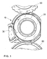
- Fig. 1 shows in section an arrangement of conveyor drums, the drum in the invention a sliding / cutting drum 10, which consists of a transport drum 20 and a cutting blade 30 arranged thereon.
- rod-shaped articles are transferred to the sliding / cutting drum 10. After transfer, the rod-shaped articles on the sliding / cutting drum 10 are displaced longitudinally axially during their conveyance to the cutting blade 30 and aligned and positioned with respect to the cutting plane of the cutting blade 30. After cutting the transported articles by means of the cutting blade 30, the articles are transferred from the transport drum 20 to a subsequent conveyor drum 60.
- the slides (see Fig. 2, reference numeral 25) are placed on the transport drum 20 under continuous rotation of the drum in a working or starting position at the transfer point of the article from the conveyor drum 50th to the sliding / cutting drum 10 to receive the articles in the receiving wells and then move longitudinally axially.
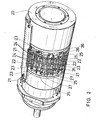
- the transport drum 20 is shown in a perspective view. For reasons of better depiction, the drawing of the cutting drum 30 provided on the transport drum 20 (see FIG.
- the rotatably driven transport drum 20 has receptacles 21, 22.
- the receptacles 21, 22 have flat or low side walls 23, so that even small or very short rod-shaped or hollow articles are safely transported in the receptacles 21, 22.
- the receptacles 21, 22 have suction holes 24 in the trough bottom, the negative pressure from the inside of the drum body 20 are applied to safely receive the conveyed articles in the receiving trough.
- a slide 25 is arranged laterally on each receptacle 21, 22, with two slides 25 each being held on a holder 26 or 27 on each side.
- the slides 25 are alternately arranged alternately at the opposite ends of the receptacles 21, 22, so that in each case two slides 25 of the receptacle 21 on a holder 27 and two slides 25 of the receptacle 22 are fastened to a holder 26.
- Each retainer 26, 27 or slider 25 is longitudinally displaceable relative to the receptacles 21, 22 to align the received articles with respect to the cutting plane of the cutter (s) (see Fig. 1, reference numeral 30).
- the cutting plane of the cutting blade 30 results from the groove-shaped separation of the receptacles 21, 22 in the transverse axial direction into which the cutting blade 30 protrudes.
- the cutting plane or the groove-shaped recess of the receptacles 21, 22 is designated in FIG. 2 by the reference numeral 31.
- the receptacles 21, 22 have a different number of suction bores on the two sides of the cutting plane 31 with respect to the cutting plane 31.
- more suction holes are provided, as on the side facing away from the slider 25 of the receptacle 21, 22nd
- the slides together with the holders 26, 27 are longitudinally movable or displaceable to the recorded Align articles with respect to the cutting plane 31 or the cutting blade.
- corresponding control cams for executing a predetermined longitudinal axial stroke are provided inside the drum body. For example, a longitudinal axial stroke by means of a corresponding control body for the movable brackets 26, 27 and slider 25 is executed.
- the sliding / cutting drum 10 according to the invention is used in machines of the tobacco-processing industry, in particular filter production machines or filter attachment machines, preferably in the filter operation of the machines.
Landscapes
- Manufacturing Of Cigar And Cigarette Tobacco (AREA)
- Cigarettes, Filters, And Manufacturing Of Filters (AREA)
- Processing And Handling Of Plastics And Other Materials For Molding In General (AREA)
- Photoreceptors In Electrophotography (AREA)
- Polishing Bodies And Polishing Tools (AREA)
Abstract
Description
- Die Erfindung betrifft eine Fördertrommel der Tabak verarbeitenden Industrie mit Aufnahmen für stabförmige Artikel der Tabak verarbeitenden Industrie und mit Verschiebemitteln zum längsaxialen Verschieben der stabförmigen Artikel in den Aufnahmen in Kombination mit einer an der Fördertrommel angeordneten Schneideinrichtung zum Schneiden der stabförmigen Artikel.
- Fördertrommeln der eingangs genannten Art werden auch als Schiebe-/Schneidtrommeln bezeichnet, die aus einer Kombination einer Transporttrommel und wenigstens einer Schneideinrichtung bzw. eines Schneidmessers für die transportierten Artikel bestehen. Diese Trommeln werden üblicherweise im Zuge der Konfektionierung von Filterstäben und von Filterzigaretten eingesetzt, wobei Filterstabkomponenten mehrfacher Gebrauchslänge im einem so genannten Querverfahren, d.h. quer zu ihren Längsachsen, durch einmalige oder mehrmalige Unterteilung, Staffelung und Hintereinanderreihung für ihre nachfolgende Verbindung mit weiteren Filterkomponenten oder Rauchartikelkomponenten vorbereitet werden. Hierfür ist eine Vielzahl von Fördertrommeln zur Ausführung der Bearbeitungsschritte notwendig. Im Zuge dieser Bearbeitungs- und Handhabungsschritte ist insbesondere eine für einen Trennschnitt an aufeinander folgenden Filterstabkomponenten erforderliche definierte längsaxiale Positionierung bzw. gegenseitige Ausrichtung der Filterstabkomponenten in ihren Aufnahmemulden für die die Länge des Förderwegs bestimmende Trommelanzahl von Bedeutung.
- In
EP-A-1 013 181 ist eine Schiebe-/Schneidtrommel offenbart, wobei die Rauchartikelkomponenten bzw. Filterstücke in den Aufnahmemulden durch Anlegen von Saugluft an Saugbohrungen der Aufnahmen gegen längsverschiebbare Anschläge auf pneumatische Weise verschoben werden. - Ausgehend von diesem Stand der Technik ist es Aufgabe der vorliegenden Erfindung, eine Schiebe-/Schneidtrommel bereit zu stellen, so dass auch sehr kurze stabförmige Artikel, d.h. insbesondere solche, deren Länge kürzer als ihr Durchmesser ist, oder hohle stabförmige Artikel der Tabak verarbeitenden Industrie zuverlässig transportiert und konfektioniert werden können.
- Gelöst wird diese Aufgabe durch eine Fördertrommel der Tabak verarbeitenden Industrie mit Aufnahmen für stabförmige Artikel der Tabak verarbeitenden Industrie und mit Verschiebemitteln zum längsaxialen Verschieben der stabförmigen Artikel in den Aufnahmen in Kombination mit einer an der Fördertrommel angeordneten Schneideinrichtung zum Schneiden der stabförmigen Artikel, die dadurch weitergebildet wird, dass die Verschiebemittel als mechanisch betätigbare und bewegbare Schieber ausgebildet sind.
- Eine erfindungsgemäße Fördertrommel wird insbesondere bei der Konfektionierung von Filterstabkomponenten eingesetzt, die aus einem Magazin in mehrfacher Gebrauchslänge entnommen und geschnitten werden. Um die geschnittenen Filterstabkomponenten nochmals durchzutrennen, ist es erforderlich, sie in eine queraxiale Reihenformation zu überführen. Zu diesem Zweck wird eine längsaxiale Verschiebung von gestaffelt aufeinander folgenden Artikeln in eine queraxiale Reihen-Schneidformation ausgeführt, wobei die stabförmigen Artikel gemäß der Erfindung mittels mechanisch betätigbarer und bewegbarer Schieber ausgerichtet werden. Dadurch ist es möglich, beispielsweise auch kleine Filterstücke oder hohle Filterstücke in den Aufnahmemulden sicher längsaxial zu verschieben bzw. auszurichten und anschließend auf der Fördertrommel zu schneiden.
- Die Handhabung von kleinen bzw. sehr kurzen Filterstücken oder stabförmigen Artikel, d.h. insbesondere von solchen, deren Länge kürzer als ihr Durchmesser ist, oder hohlen Filterstücken ist bei Fördertrommeln bzw. Schiebe-/Schneidtrommel, bei denen die Artikel auf pneumatische Weise längsaxial verschoben werden, schwierig bzw. unter Umständen unmöglich, da kurze Filterstücke zum Umkippen neigen. Ein zusätzlicher Nachteil des pneumatischen Verschiebens ist die sehr tiefe Ausbildung der Aufnahmemulden. Je tiefer ein Mulde ist, desto komplizierter ist die Übergabe der stabförmigen Artikel an eine nachfolgende Trommel. Im Gegensatz dazu kann bei Einsatz der erfindungsgemäßen mechanischen Schieber eine Aufnahmemulde auf der Fördertrommel flacher ausgebildet sein, um eine sichere Übergabe an die nachfolgende Trommel zu gewährleisten. Darüber hinaus wird durch die mechanischen Schieber viel Saugluft eingespart, da die Artikel nicht mehr pneumatisch sondern mechanisch bewegt werden und daher weniger Saugbohrungen an der Transporttrommel erforderlich sind. Die vorhandenen Saugbohrungen haben vornehmlich die Funktion, die geförderten Artikel in den Mulden zu halten.
- In einer bevorzugten Ausführungsform sind die Schieber in Bezug auf die Aufnahmen längsverschiebbar, so dass die Schieber die aufgenommenen stabförmigen Artikel in Bezug auf die Schneidebene der Schneideinrichtung exakt ausrichten und positionieren. Zum Schneiden der ausgerichteten Artikel sind als Schneideinrichtung ein oder mehrere Schneidmesser an der Fördertrommel vorgesehen.
- Insbesondere sind die Schieber in queraxialer Richtung der Aufnahmen wechselseitig alternierend angeordnet, so dass die Schieber in Bezug auf die Ebene der Schneidmesser bzw. der Schneideinrichtung abwechselnd in Bezug auf die Schneidebene ausgerichtet sind.
- Eine Vereinfachung der Bewegungsabläufe wird erreicht, wenn mehrere Schieber gleichzeitig miteinander bewegbar sind. Hierzu sind mehrere Schieber beispielsweise auf einer Halterung angeordnet, so dass die Schieber die Artikel durch Bewegung der Halterung zuverlässig in Bezug auf die Schneidebene ausrichten.
- Hierzu ist vorgesehen, dass die Schieber einen vorbestimmten längsaxialen Hub ausführen.
- Des Weiteren ist es bevorzugt, wenn die Aufnahmen jeweils in Bezug auf die Schneidebene der Schneideinrichtung auf beiden Seiten der Schneidebene eine unterschiedliche Anzahl von mit Unterdruck beaufschlagbaren Saugbohrungen aufweisen. Hierdurch werden auf effiziente Weise in den Aufnahmemulden eine geringe und ausreichende Anzahl von Saugbohrungen mit Unterdruck beaufschlagt, die eine sichere Aufnahme und längsaxiale Führung der geförderten bzw. geschnittenen Artikel gewährleisten.
- Insbesondere ist die Fördertrommel in Kombination mit der Schneideinrichtung als so genannte Schiebe-/Schneidtrommel ausgebildet.
- Ferner wird die Aufgabe gelöst durch eine Maschine der Tabak verarbeitenden Industrie, insbesondere Filterherstellungsmaschine oder Filteransetzmaschine, die mit einer voranstehend beschriebenen erfindungsgemäßen Fördertrommel ausgestattet ist. Zur Vermeidung von Wiederholungen wird auf die obigen Ausführungen ausdrücklich verwiesen.
- Die Erfindung wird nachstehend ohne Beschränkung des allgemeinen Erfindungsgedankens unter Bezugnahme auf die Zeichnungen exemplarisch beschrieben, auf die im Übrigen bezüglich der Offenbarung aller im Text nicht näher erläuterten erfindungsgemäßen Einzelheiten ausdrücklich verwiesen wird. Es zeigen:
- Fig. 1
- eine ausschnittsweise Ansicht einer Schiebe-/Schneidtrommel und
- Fig. 2
- eine perspektivische Ansicht der erfindungsgemäßen Schiebe-/Schneidtrommel im Ausschnitt.
- In den folgenden Figuren sind jeweils gleiche oder gleichartige Elemente bzw. entsprechende Teile mit denselben Bezugsziffern versehen, so dass von einer entsprechenden erneuten Vorstellung abgesehen wird.
- Fig. 1 zeigt im Ausschnitt eine Anordnung von Fördertrommeln, die im Trommellauf eine erfindungsgemäße Schiebe-/Schneidtrommel 10 aufweist, die aus einer Transporttrommel 20 und einem daran angeordneten Schneidmesser 30 besteht.
- Von einer Fördertrommel 50 werden stabförmige Artikel an die Schiebe-/Schneidtrommel 10 übergeben. Nach der Übergabe werden die stabförmigen Artikel auf der Schiebe-/Schneidtrommel 10 während ihrer Förderung zum Schneidmesser 30 längsaxial verschoben und in Bezug auf die Schneidebene des Schneidmessers 30 ausgerichtet und positioniert. Nach dem Schneiden der transportierten Artikel mittels des Schneidmessers 30 werden die Artikel von der Transporttrommel 20 an eine nachfolgende Fördertrommel 60 übergeben.
- Im Anschluss an die Entnahme der geschnittenen Artikel von der Transporttrommel 20 werden die Schieber (siehe Fig. 2, Bezugszeichen 25) auf der Transporttrommel 20 unter fortlaufender Rotation der Trommel in eine Arbeitsposition bzw. Startposition gebracht, um am Übergabepunkt der Artikel von der Fördertrommel 50 an die Schiebe-/Schneidtrommel 10 die Artikel in den Aufnahmemulden aufzunehmen und danach längsaxial zu bewegen.
- In Fig. 2 ist die Transporttrommel 20 in einer perspektivischen Darstellung gezeigt. Aus Gründen der besseren Darstellbarkeit wurde in Fig. 2 von der Einzeichnung des an der Transporttrommel 20 vorgesehenen Schneidmessers 30 (vgl. Fig. 1) abgesehen.
- Die rotierend angetriebene Transporttrommel 20 verfügt über Aufnahmen 21, 22. Die Aufnahmen 21, 22 verfügen über flache bzw. niedrige Seitenwände 23, so dass auch kleine bzw. sehr kurze stabförmige oder hohle Artikel sicher in den Aufnahmen 21, 22 transportiert werden. Ferner verfügen die Aufnahmen 21, 22 über Saugbohrungen 24 im Muldengrund, die mit Unterdruck von der Innenseite des Trommelkörpers 20 beaufschlagt werden, um die geförderten Artikel sicher in der Aufnahmemulde aufzunehmen.
- Seitlich sind an jeder Aufnahme 21, 22 jeweils ein Schieber 25 angeordnet, wobei jeweils zwei Schieber 25 auf jeder Seite auf einer Halterung 26 bzw. 27 gehalten werden. Die Schieber 25 sind alternierend wechselseitig an den gegenüberliegenden Enden der Aufnahmen 21, 22 angeordnet, so dass jeweils zwei Schieber 25 der Aufnahme 21 an einer Halterung 27 und jeweils zwei Schieber 25 der Aufnahme 22 an einer Halterung 26 befesigt sind.
- Jede Halterung 26, 27 bzw. jeder Schieber 25 ist längsaxial in Bezug auf die Aufnahmen 21, 22 verschiebbar, um die aufgenommenen Artikel in Bezug auf die Schneidebene der Schneideinrichtung bzw. der Schneidmesser (vgl. Fig. 1, Bezugszeichen 30) auszurichten.
- Die Schneidebene des Schneidmessers 30 (vgl. Fig. 1) ergibt sich durch die nutförmige Durchtrennung der Aufnahmen 21, 22 in queraxialer Richtung, in die das Schneidmesser 30 hineinragt. Die Schneidebene bzw. die nutförmige Vertiefung der Aufnahmen 21, 22 ist in Fig. 2 mit dem Bezugszeichen 31 bezeichnet.
- Darüber hinaus ist in Fig. 2 erkennbar, dass die Aufnahmen 21, 22 in Bezug auf die Schneidebene 31 eine unterschiedliche Anzahl von Saugbohrungen auf den beiden Seiten der Schneidebene 31 aufweisen. Auf derjenigen Seite, auf der jeweils ein Schieber 25 angeordnet ist, sind mehr Saugbohrungen vorgesehen, als auf der vom Schieber 25 abgewandten Seite der Aufnahme 21, 22.
- Erfindungsgemäß sind die Schieber zusammen mit den Halterungen 26, 27 längsaxial bewegbar bzw. verschiebbar, um die aufgenommenen Artikel in Bezug auf die Schneidebene 31 bzw. das Schneidmesser auszurichten. Um die Halterungen 26, 27 bzw. die Schieber 25 bewegen zu können, sind im Inneren des Trommelkörpers 20 entsprechende Steuerkurven zur Ausführung eines vorbestimmten längsaxialen Hubes vorgesehen. Beispielsweise wird ein längsaxialer Hub mittels eines entsprechenden Steuerkörpers für die bewegbaren Halterungen 26, 27 bzw. Schieber 25 ausgeführt.
- Die erfindungsgemäße Schiebe-/Schneidtrommel 10 wird in Maschinen der Tabak verarbeitenden Industrie, insbesondere Filterherstellungsmaschinen bzw. Filteransetzmaschinen, vorzugsweise im Filterlauf der Maschinen, eingesetzt.
-
- 10
- Schiebe-/Schneidtrommel
- 20
- Transporttrommel
- 21
- Aufnahme
- 22
- Aufnahme
- 23
- Seitenwand
- 24
- Saugbohrung
- 25
- Schieber
- 26
- Halterung
- 27
- Halterung
- 30
- Schneidmesser
- 31
- Schneidebene
- 50
- Fördertrommel
- 60
- Fördertrommel
Claims (8)
- Fördertrommel (20) der Tabak verarbeitenden Industrie mit Aufnahmen (21, 22) für stabförmige Artikel der Tabak verarbeitenden Industrie und mit Verschiebemitteln (25, 26) zum längsaxialen Verschieben der stabförmigen Artikel in den Aufnahmen (21, 22) in Kombination mit einer an der Fördertrommel (20) angeordneten Schneideinrichtung (30) zum Schneiden der stabförmigen Artikel, dadurch gekennzeichnet, dass die Verschiebemittel (25, 26) als mechanisch betätigbare und bewegbare Schieber (25) ausgebildet sind.
- Fördertrommel (20) nach Anspruch 1, dadurch gekennzeichnet, dass die Schieber (25) in Bezug auf die Aufnahmen (21, 22) längsverschiebbar sind.
- Fördertrommel (20) nach Anspruch 1 oder 2, dadurch gekennzeichnet, dass die Schieber (25) in queraxialer Richtung der Aufnahmen (21, 22) wechselseitig alternierend angeordnet sind.
- Fördertrommel (20) nach einem der Ansprüche 1 bis 3, dadurch gekennzeichnet, dass mehrere Schieber (25) gleichzeitig miteinander bewegbar sind.
- Fördertrommel (20) nach einem oder mehreren der Ansprüche 1 bis 4, dadurch gekennzeichnet, dass die Schieber (25) einen vorbestimmten längsaxialen Hub ausführen.
- Fördertrommel (20) nach einem oder mehreren der Ansprüche 1 bis 5, dadurch gekennzeichnet, dass die Aufnahmen (21, 22) jeweils in Bezug auf die Schneidebene (31) der Schneideinrichtung (30) auf beiden Seiten der Schneidebene (31) eine unterschiedliche Anzahl von mit Unterdruck beaufschlagbaren Saugbohrungen (24) aufweisen.
- Fördertrommel (20) nach einem oder mehreren der Ansprüche 1 bis 6, dadurch gekennzeichnet, dass die Fördertrommel (20) mit der Schneideinrichtung (30) als Schiebe-/Schneidtrommel (10) ausgebildet ist.
- Maschine der Tabak verarbeitenden Industrie, insbesondere Filterherstellungsmaschine oder Filteransetzmaschine, mit einer Fördertrommel (20) nach einem oder mehreren der Ansprüche 1 bis 7.
Priority Applications (1)
| Application Number | Priority Date | Filing Date | Title |
|---|---|---|---|
| PL06002526T PL1700528T3 (pl) | 2005-03-10 | 2006-02-08 | Bęben przesuwająco-tnący |
Applications Claiming Priority (1)
| Application Number | Priority Date | Filing Date | Title |
|---|---|---|---|
| DE102005011543A DE102005011543A1 (de) | 2005-03-10 | 2005-03-10 | Schiebe-/Schneidtrommel |
Publications (2)
| Publication Number | Publication Date |
|---|---|
| EP1700528A1 true EP1700528A1 (de) | 2006-09-13 |
| EP1700528B1 EP1700528B1 (de) | 2010-11-10 |
Family
ID=36579364
Family Applications (1)
| Application Number | Title | Priority Date | Filing Date |
|---|---|---|---|
| EP06002526A Expired - Lifetime EP1700528B1 (de) | 2005-03-10 | 2006-02-08 | Schiebe-/Schneidtrommel |
Country Status (7)
| Country | Link |
|---|---|
| US (1) | US20060201525A1 (de) |
| EP (1) | EP1700528B1 (de) |
| JP (1) | JP4891633B2 (de) |
| CN (1) | CN1830339B (de) |
| AT (1) | ATE487393T1 (de) |
| DE (2) | DE102005011543A1 (de) |
| PL (1) | PL1700528T3 (de) |
Cited By (7)
| Publication number | Priority date | Publication date | Assignee | Title |
|---|---|---|---|---|
| EP2668857A2 (de) | 2012-05-30 | 2013-12-04 | HAUNI Maschinenbau AG | Fördertrommel der Tabak verarbeitenden Industrie |
| EP2862455A1 (de) | 2013-10-17 | 2015-04-22 | HAUNI Maschinenbau AG | Schneiden von stabförmigen Artikeln der Tabak verarbeitenden Industrie |
| CN107455792A (zh) * | 2016-06-06 | 2017-12-12 | 上海宏昌烟草机械有限公司 | 一种在废烟支处理机组上应用的新型校直及切割装置 |
| DE102016114641A1 (de) | 2016-08-08 | 2018-02-08 | Hauni Maschinenbau Gmbh | Fördertrommel der Tabak verarbeitenden Industrie |
| CN109090704A (zh) * | 2018-08-10 | 2018-12-28 | 红塔烟草(集团)有限责任公司 | 一种卷烟滤棒分切设备 |
| WO2022157031A1 (de) | 2021-01-25 | 2022-07-28 | Hauni Maschinenbau Gmbh | Trommelanordnung zum queraxialen fördern von stabförmigen artiikeln der tabak verarbeitenden industrie |
| EP4666879A1 (de) | 2024-06-17 | 2025-12-24 | Körber Technologies GmbH | Trommelanordnung zum queraxialen fördern von stabförmigen artikeln der tabak verarbeitenden industrie |
Families Citing this family (13)
| Publication number | Priority date | Publication date | Assignee | Title |
|---|---|---|---|---|
| DE102006049409A1 (de) * | 2006-10-16 | 2008-04-17 | Hauni Maschinenbau Aktiengesellschaft | Taumelrolle |
| DE102008035383B4 (de) * | 2008-07-29 | 2013-02-07 | Hauni Maschinenbau Ag | Fördertrommeln der Tabak verarbeitenden Industrie |
| PL3032971T3 (pl) * | 2013-08-14 | 2020-05-18 | Philip Morris Products S.A. | Sposób i układ do owijania zestawu segmentów |
| CN103674648B (zh) * | 2013-12-13 | 2016-08-17 | 上海烟草集团有限责任公司 | 一种分切卷烟滤棒的方法 |
| PL233095B1 (pl) * | 2015-07-16 | 2019-09-30 | Int Tobacco Machinery Poland Spolka Z Ograniczona Odpowiedzialnoscia | Sposób przesuwania artykułów prętopodobnych, oraz urządzenie do przesuwania artykułów prętopodobnych |
| PL414414A1 (pl) * | 2015-10-20 | 2017-04-24 | International Tobacco Machinery Poland Spółka Z Ograniczoną Odpowiedzialnością | Urządzenie i sposób do osiowego centrowania artykułu prętopodobnego lub grupy artykułów prętopodobnych i wielostopniowy zespół do cięcia artykułu prętopodobnego lub grupy artykułów prętopodobnych |
| CN112956734A (zh) * | 2017-12-25 | 2021-06-15 | 赵牧青 | 滑块轮式烟支分离装置 |
| DE102018104956A1 (de) * | 2018-03-05 | 2019-09-05 | Hauni Maschinenbau Gmbh | Fördertrommel der Tabak verarbeitenden Industrie |
| CN109007960B (zh) * | 2018-08-22 | 2021-12-28 | 青岛颐中科技有限公司 | 一种多段复合烟支生产设备及其使用方法 |
| CN112123386A (zh) * | 2020-09-09 | 2020-12-25 | 贵州中烟工业有限责任公司 | 滤棒轴向切割装置 |
| DE102020128187A1 (de) * | 2020-10-27 | 2022-04-28 | Hauni Maschinenbau Gmbh | Übergabevorrichtung der Tabak verarbeitenden Industrie |
| IT202000029435A1 (it) | 2020-12-02 | 2022-06-02 | Gd Spa | Macchina operatrice per la lavorazione di articoli da fumo con un componente pneumatico realizzato mediante manifattura additiva |
| EP4480328B1 (de) * | 2023-06-23 | 2025-11-12 | International Tobacco Machinery Poland Sp. z o.o. | Schiebetrommel der tabak verarbeitenden industrie und verfahren zu deren betrieb |
Citations (4)
| Publication number | Priority date | Publication date | Assignee | Title |
|---|---|---|---|---|
| DE1173825B (de) | 1961-09-30 | 1964-07-09 | Hauni Werke Koerber & Co Kg | Vorrichtung zum Staffeln von aus Filterstaeben oder anderen stabfoermigen Gegenstaenden hergestellten Stabteilen |
| DE4242326A1 (de) | 1991-12-17 | 1993-06-24 | Gd Spa | |
| EP1013181A2 (de) | 1998-12-18 | 2000-06-28 | Hauni Maschinenbau AG | Vorrichtung zum längsaxialen Positionieren von zu durchtrennenden stabförmigen Artikeln der tabakverarbeitenden Industrie |
| US20040255963A1 (en) | 2001-11-19 | 2004-12-23 | Heinz Focke | Method and device for producing filter cigarettes |
Family Cites Families (11)
| Publication number | Priority date | Publication date | Assignee | Title |
|---|---|---|---|---|
| US3286809A (en) * | 1963-11-28 | 1966-11-22 | Hauni Werke Koerber & Co Kg | Method and apparatus for manipulating rod shaped articles |
| DE2640567A1 (de) * | 1976-09-09 | 1978-03-16 | Hauni Werke Koerber & Co Kg | Vorrichtung zum schneiden und auseinanderziehen von filterstaeben bzw. filterstabteilen |
| IT1163486B (it) * | 1982-07-03 | 1987-04-08 | Hauni Werke Koerber & Co Kg | Procedimento e dispositivo per produrre sigarette semplici senza bocchino |
| US4554931A (en) * | 1982-10-15 | 1985-11-26 | Hauni-Werke Korber & Co. Kg | Apparatus for severing rod-shaped articles of the tobacco processing industry |
| US4564029A (en) * | 1983-09-13 | 1986-01-14 | Hauni-Werke Korber & Co. Kg | Method and apparatus for assembling plain cigarettes with filter rod section |
| JP3293184B2 (ja) * | 1992-08-24 | 2002-06-17 | 日本たばこ産業株式会社 | フィルタ付き紙巻たばこ製造機の排出装置 |
| JP3437634B2 (ja) * | 1994-03-31 | 2003-08-18 | 日本たばこ産業株式会社 | フィルタプラグ供給装置の同軸移動整列装置 |
| DE19540158C2 (de) * | 1995-10-27 | 1997-10-16 | Polytype Maschf Sa | Übergabevorrichtung |
| EP1419705A1 (de) * | 2001-06-19 | 2004-05-19 | Japan Tobacco Inc. | Vorrichtung zum ausstossen von stangenähnlichen objekten |
| DE10351068B4 (de) * | 2003-10-30 | 2006-06-22 | Hauni Maschinenbau Ag | Staffeltrommel |
| DE10351070B4 (de) * | 2003-10-30 | 2006-06-22 | Hauni Maschinenbau Ag | Staffeltrommel |
-
2005
- 2005-03-10 DE DE102005011543A patent/DE102005011543A1/de not_active Withdrawn
-
2006
- 2006-02-08 DE DE502006008261T patent/DE502006008261D1/de not_active Expired - Lifetime
- 2006-02-08 EP EP06002526A patent/EP1700528B1/de not_active Expired - Lifetime
- 2006-02-08 PL PL06002526T patent/PL1700528T3/pl unknown
- 2006-02-08 AT AT06002526T patent/ATE487393T1/de active
- 2006-03-03 JP JP2006057608A patent/JP4891633B2/ja not_active Expired - Fee Related
- 2006-03-07 US US11/368,478 patent/US20060201525A1/en not_active Abandoned
- 2006-03-10 CN CN2006100595296A patent/CN1830339B/zh not_active Expired - Fee Related
Patent Citations (4)
| Publication number | Priority date | Publication date | Assignee | Title |
|---|---|---|---|---|
| DE1173825B (de) | 1961-09-30 | 1964-07-09 | Hauni Werke Koerber & Co Kg | Vorrichtung zum Staffeln von aus Filterstaeben oder anderen stabfoermigen Gegenstaenden hergestellten Stabteilen |
| DE4242326A1 (de) | 1991-12-17 | 1993-06-24 | Gd Spa | |
| EP1013181A2 (de) | 1998-12-18 | 2000-06-28 | Hauni Maschinenbau AG | Vorrichtung zum längsaxialen Positionieren von zu durchtrennenden stabförmigen Artikeln der tabakverarbeitenden Industrie |
| US20040255963A1 (en) | 2001-11-19 | 2004-12-23 | Heinz Focke | Method and device for producing filter cigarettes |
Cited By (11)
| Publication number | Priority date | Publication date | Assignee | Title |
|---|---|---|---|---|
| EP2668857A2 (de) | 2012-05-30 | 2013-12-04 | HAUNI Maschinenbau AG | Fördertrommel der Tabak verarbeitenden Industrie |
| DE102012209032A1 (de) | 2012-05-30 | 2013-12-05 | Hauni Maschinenbau Ag | Fördertrommel der Tabak verarbeitenden Industrie |
| EP2862455A1 (de) | 2013-10-17 | 2015-04-22 | HAUNI Maschinenbau AG | Schneiden von stabförmigen Artikeln der Tabak verarbeitenden Industrie |
| DE102013221115A1 (de) | 2013-10-17 | 2015-04-23 | Hauni Maschinenbau Ag | Schneiden von stabförmigen Artikeln der Tabak verarbeitenden Industrie |
| CN107455792A (zh) * | 2016-06-06 | 2017-12-12 | 上海宏昌烟草机械有限公司 | 一种在废烟支处理机组上应用的新型校直及切割装置 |
| DE102016114641A1 (de) | 2016-08-08 | 2018-02-08 | Hauni Maschinenbau Gmbh | Fördertrommel der Tabak verarbeitenden Industrie |
| CN109090704A (zh) * | 2018-08-10 | 2018-12-28 | 红塔烟草(集团)有限责任公司 | 一种卷烟滤棒分切设备 |
| CN109090704B (zh) * | 2018-08-10 | 2020-09-22 | 红塔烟草(集团)有限责任公司 | 一种卷烟滤棒分切设备 |
| WO2022157031A1 (de) | 2021-01-25 | 2022-07-28 | Hauni Maschinenbau Gmbh | Trommelanordnung zum queraxialen fördern von stabförmigen artiikeln der tabak verarbeitenden industrie |
| DE102021101485A1 (de) | 2021-01-25 | 2022-07-28 | Hauni Maschinenbau Gmbh | Trommelanordnung zum queraxialen Fördern von stabförmigen Artikeln der Tabak verarbeitenden Industrie |
| EP4666879A1 (de) | 2024-06-17 | 2025-12-24 | Körber Technologies GmbH | Trommelanordnung zum queraxialen fördern von stabförmigen artikeln der tabak verarbeitenden industrie |
Also Published As
| Publication number | Publication date |
|---|---|
| DE502006008261D1 (de) | 2010-12-23 |
| JP4891633B2 (ja) | 2012-03-07 |
| DE102005011543A1 (de) | 2006-09-14 |
| PL1700528T3 (pl) | 2011-04-29 |
| ATE487393T1 (de) | 2010-11-15 |
| CN1830339B (zh) | 2010-06-16 |
| US20060201525A1 (en) | 2006-09-14 |
| EP1700528B1 (de) | 2010-11-10 |
| JP2006246887A (ja) | 2006-09-21 |
| CN1830339A (zh) | 2006-09-13 |
Similar Documents
| Publication | Publication Date | Title |
|---|---|---|
| EP1700528B1 (de) | Schiebe-/Schneidtrommel | |
| EP3141134B1 (de) | Schiebetrommel der tabak verarbeitenden industrie | |
| EP3536173B1 (de) | Fördertrommel der tabak verarbeitenden industrie | |
| EP1013181A2 (de) | Vorrichtung zum längsaxialen Positionieren von zu durchtrennenden stabförmigen Artikeln der tabakverarbeitenden Industrie | |
| EP2659792B1 (de) | Verfahren und Einrichtung zum Zusammenstellen von Filtersegmentgruppen | |
| DE102012209032A1 (de) | Fördertrommel der Tabak verarbeitenden Industrie | |
| EP2688431A1 (de) | Herstellung von filterstopfen bzw. von filterzigaretten | |
| EP3536172B1 (de) | Schiebetrommel der tabak verarbeitenden industrie | |
| DE102017127593A1 (de) | Schiebetrommel der Tabak verarbeitenden Industrie | |
| EP3281537A2 (de) | Fördertrommel der tabak verarbeitenden industrie | |
| DE3201859A1 (de) | Verfahren und vorrichtung zum verbinden von stabfoermigen artikeln der tabakverarbeitenden industrie mittels eines verbindungsstreifens | |
| EP1532878B1 (de) | Staffeltrommel | |
| DE102013210634A1 (de) | Schiebetrommel für eine Maschine der Tabak verarbeitenden Industrie | |
| EP3677128B1 (de) | Fördern von stabförmigen artikeln der tabak verarbeitenden industrie | |
| EP4369955B1 (de) | Fördertrommel der tabak verarbeitenden industrie | |
| EP4266913B1 (de) | Trommelanordnung zum queraxialen fördern von stabförmigen artikeln der tabak verarbeitenden industrie | |
| DE10351070B4 (de) | Staffeltrommel | |
| EP2696707B1 (de) | Förderung von stabförmigen artikeln der tabak verarbeitenden industrie | |
| DE2724936C3 (de) | Maschine zum automatischen Teilen zugeführter zylindrischer Hülsen | |
| AT527682B1 (de) | Haltevorrichtung | |
| DE102024116975A1 (de) | Trommelanordnung zum queraxialen Fördern von stabförmigen Artikeln der Tabak verarbeitenden Industrie | |
| EP4265129A1 (de) | Fördern von stabförmigen artikeln der tabak verarbeitenden industrie | |
| DE1279520B (de) | Vorrichtung zum Zerschneiden von auf einem Kreisumfang bewegten Zigarettenfiltereinlagen oder anderen stabfoermigen Gegenstaenden | |
| DE102020120519A1 (de) | Schiebetrommel der Tabak verarbeitenden Industrie | |
| DE102004035063A1 (de) | Abstandslose Verbindungsblättchen |
Legal Events
| Date | Code | Title | Description |
|---|---|---|---|
| PUAI | Public reference made under article 153(3) epc to a published international application that has entered the european phase |
Free format text: ORIGINAL CODE: 0009012 |
|
| AK | Designated contracting states |
Kind code of ref document: A1 Designated state(s): AT BE BG CH CY CZ DE DK EE ES FI FR GB GR HU IE IS IT LI LT LU LV MC NL PL PT RO SE SI SK TR |
|
| AX | Request for extension of the european patent |
Extension state: AL BA HR MK YU |
|
| 17P | Request for examination filed |
Effective date: 20070215 |
|
| 17Q | First examination report despatched |
Effective date: 20070315 |
|
| AKX | Designation fees paid |
Designated state(s): AT BE BG CH CY CZ DE DK EE ES FI FR GB GR HU IE IS IT LI LT LU LV MC NL PL PT RO SE SI SK TR |
|
| TPAC | Observations filed by third parties |
Free format text: ORIGINAL CODE: EPIDOSNTIPA |
|
| GRAP | Despatch of communication of intention to grant a patent |
Free format text: ORIGINAL CODE: EPIDOSNIGR1 |
|
| GRAS | Grant fee paid |
Free format text: ORIGINAL CODE: EPIDOSNIGR3 |
|
| GRAA | (expected) grant |
Free format text: ORIGINAL CODE: 0009210 |
|
| AK | Designated contracting states |
Kind code of ref document: B1 Designated state(s): AT BE BG CH CY CZ DE DK EE ES FI FR GB GR HU IE IS IT LI LT LU LV MC NL PL PT RO SE SI SK TR |
|
| REG | Reference to a national code |
Ref country code: GB Ref legal event code: FG4D Free format text: NOT ENGLISH |
|
| REG | Reference to a national code |
Ref country code: CH Ref legal event code: EP |
|
| REG | Reference to a national code |
Ref country code: IE Ref legal event code: FG4D Free format text: LANGUAGE OF EP DOCUMENT: GERMAN |
|
| REF | Corresponds to: |
Ref document number: 502006008261 Country of ref document: DE Date of ref document: 20101223 Kind code of ref document: P |
|
| REG | Reference to a national code |
Ref country code: NL Ref legal event code: T3 |
|
| LTIE | Lt: invalidation of european patent or patent extension |
Effective date: 20101110 |
|
| PG25 | Lapsed in a contracting state [announced via postgrant information from national office to epo] |
Ref country code: LT Free format text: LAPSE BECAUSE OF FAILURE TO SUBMIT A TRANSLATION OF THE DESCRIPTION OR TO PAY THE FEE WITHIN THE PRESCRIBED TIME-LIMIT Effective date: 20101110 |
|
| REG | Reference to a national code |
Ref country code: PL Ref legal event code: T3 |
|
| PG25 | Lapsed in a contracting state [announced via postgrant information from national office to epo] |
Ref country code: SE Free format text: LAPSE BECAUSE OF FAILURE TO SUBMIT A TRANSLATION OF THE DESCRIPTION OR TO PAY THE FEE WITHIN THE PRESCRIBED TIME-LIMIT Effective date: 20101110 Ref country code: IS Free format text: LAPSE BECAUSE OF FAILURE TO SUBMIT A TRANSLATION OF THE DESCRIPTION OR TO PAY THE FEE WITHIN THE PRESCRIBED TIME-LIMIT Effective date: 20110310 Ref country code: BG Free format text: LAPSE BECAUSE OF FAILURE TO SUBMIT A TRANSLATION OF THE DESCRIPTION OR TO PAY THE FEE WITHIN THE PRESCRIBED TIME-LIMIT Effective date: 20110210 Ref country code: PT Free format text: LAPSE BECAUSE OF FAILURE TO SUBMIT A TRANSLATION OF THE DESCRIPTION OR TO PAY THE FEE WITHIN THE PRESCRIBED TIME-LIMIT Effective date: 20110310 Ref country code: CY Free format text: LAPSE BECAUSE OF FAILURE TO SUBMIT A TRANSLATION OF THE DESCRIPTION OR TO PAY THE FEE WITHIN THE PRESCRIBED TIME-LIMIT Effective date: 20101110 Ref country code: SI Free format text: LAPSE BECAUSE OF FAILURE TO SUBMIT A TRANSLATION OF THE DESCRIPTION OR TO PAY THE FEE WITHIN THE PRESCRIBED TIME-LIMIT Effective date: 20101110 Ref country code: LV Free format text: LAPSE BECAUSE OF FAILURE TO SUBMIT A TRANSLATION OF THE DESCRIPTION OR TO PAY THE FEE WITHIN THE PRESCRIBED TIME-LIMIT Effective date: 20101110 Ref country code: FI Free format text: LAPSE BECAUSE OF FAILURE TO SUBMIT A TRANSLATION OF THE DESCRIPTION OR TO PAY THE FEE WITHIN THE PRESCRIBED TIME-LIMIT Effective date: 20101110 |
|
| REG | Reference to a national code |
Ref country code: IE Ref legal event code: FD4D |
|
| PG25 | Lapsed in a contracting state [announced via postgrant information from national office to epo] |
Ref country code: GR Free format text: LAPSE BECAUSE OF FAILURE TO SUBMIT A TRANSLATION OF THE DESCRIPTION OR TO PAY THE FEE WITHIN THE PRESCRIBED TIME-LIMIT Effective date: 20110211 |
|
| PG25 | Lapsed in a contracting state [announced via postgrant information from national office to epo] |
Ref country code: IE Free format text: LAPSE BECAUSE OF FAILURE TO SUBMIT A TRANSLATION OF THE DESCRIPTION OR TO PAY THE FEE WITHIN THE PRESCRIBED TIME-LIMIT Effective date: 20101110 Ref country code: ES Free format text: LAPSE BECAUSE OF FAILURE TO SUBMIT A TRANSLATION OF THE DESCRIPTION OR TO PAY THE FEE WITHIN THE PRESCRIBED TIME-LIMIT Effective date: 20110221 Ref country code: EE Free format text: LAPSE BECAUSE OF FAILURE TO SUBMIT A TRANSLATION OF THE DESCRIPTION OR TO PAY THE FEE WITHIN THE PRESCRIBED TIME-LIMIT Effective date: 20101110 Ref country code: CZ Free format text: LAPSE BECAUSE OF FAILURE TO SUBMIT A TRANSLATION OF THE DESCRIPTION OR TO PAY THE FEE WITHIN THE PRESCRIBED TIME-LIMIT Effective date: 20101110 |
|
| BERE | Be: lapsed |
Owner name: HAUNI MASCHINENBAU A.G. Effective date: 20110228 |
|
| PG25 | Lapsed in a contracting state [announced via postgrant information from national office to epo] |
Ref country code: RO Free format text: LAPSE BECAUSE OF FAILURE TO SUBMIT A TRANSLATION OF THE DESCRIPTION OR TO PAY THE FEE WITHIN THE PRESCRIBED TIME-LIMIT Effective date: 20101110 Ref country code: DK Free format text: LAPSE BECAUSE OF FAILURE TO SUBMIT A TRANSLATION OF THE DESCRIPTION OR TO PAY THE FEE WITHIN THE PRESCRIBED TIME-LIMIT Effective date: 20101110 Ref country code: SK Free format text: LAPSE BECAUSE OF FAILURE TO SUBMIT A TRANSLATION OF THE DESCRIPTION OR TO PAY THE FEE WITHIN THE PRESCRIBED TIME-LIMIT Effective date: 20101110 |
|
| PLBE | No opposition filed within time limit |
Free format text: ORIGINAL CODE: 0009261 |
|
| STAA | Information on the status of an ep patent application or granted ep patent |
Free format text: STATUS: NO OPPOSITION FILED WITHIN TIME LIMIT |
|
| PG25 | Lapsed in a contracting state [announced via postgrant information from national office to epo] |
Ref country code: MC Free format text: LAPSE BECAUSE OF NON-PAYMENT OF DUE FEES Effective date: 20110228 |
|
| REG | Reference to a national code |
Ref country code: CH Ref legal event code: PL |
|
| 26N | No opposition filed |
Effective date: 20110811 |
|
| GBPC | Gb: european patent ceased through non-payment of renewal fee |
Effective date: 20110210 |
|
| PG25 | Lapsed in a contracting state [announced via postgrant information from national office to epo] |
Ref country code: CH Free format text: LAPSE BECAUSE OF NON-PAYMENT OF DUE FEES Effective date: 20110228 Ref country code: LI Free format text: LAPSE BECAUSE OF NON-PAYMENT OF DUE FEES Effective date: 20110228 |
|
| REG | Reference to a national code |
Ref country code: FR Ref legal event code: ST Effective date: 20111102 |
|
| PG25 | Lapsed in a contracting state [announced via postgrant information from national office to epo] |
Ref country code: BE Free format text: LAPSE BECAUSE OF NON-PAYMENT OF DUE FEES Effective date: 20110228 |
|
| REG | Reference to a national code |
Ref country code: DE Ref legal event code: R097 Ref document number: 502006008261 Country of ref document: DE Effective date: 20110811 |
|
| PG25 | Lapsed in a contracting state [announced via postgrant information from national office to epo] |
Ref country code: FR Free format text: LAPSE BECAUSE OF NON-PAYMENT OF DUE FEES Effective date: 20110228 |
|
| PG25 | Lapsed in a contracting state [announced via postgrant information from national office to epo] |
Ref country code: GB Free format text: LAPSE BECAUSE OF NON-PAYMENT OF DUE FEES Effective date: 20110210 |
|
| REG | Reference to a national code |
Ref country code: AT Ref legal event code: MM01 Ref document number: 487393 Country of ref document: AT Kind code of ref document: T Effective date: 20110208 |
|
| PG25 | Lapsed in a contracting state [announced via postgrant information from national office to epo] |
Ref country code: AT Free format text: LAPSE BECAUSE OF NON-PAYMENT OF DUE FEES Effective date: 20110208 |
|
| PG25 | Lapsed in a contracting state [announced via postgrant information from national office to epo] |
Ref country code: LU Free format text: LAPSE BECAUSE OF NON-PAYMENT OF DUE FEES Effective date: 20110208 |
|
| PG25 | Lapsed in a contracting state [announced via postgrant information from national office to epo] |
Ref country code: TR Free format text: LAPSE BECAUSE OF FAILURE TO SUBMIT A TRANSLATION OF THE DESCRIPTION OR TO PAY THE FEE WITHIN THE PRESCRIBED TIME-LIMIT Effective date: 20101110 |
|
| PG25 | Lapsed in a contracting state [announced via postgrant information from national office to epo] |
Ref country code: HU Free format text: LAPSE BECAUSE OF FAILURE TO SUBMIT A TRANSLATION OF THE DESCRIPTION OR TO PAY THE FEE WITHIN THE PRESCRIBED TIME-LIMIT Effective date: 20101110 |
|
| PGFP | Annual fee paid to national office [announced via postgrant information from national office to epo] |
Ref country code: NL Payment date: 20140224 Year of fee payment: 9 |
|
| PGFP | Annual fee paid to national office [announced via postgrant information from national office to epo] |
Ref country code: PL Payment date: 20140122 Year of fee payment: 9 |
|
| REG | Reference to a national code |
Ref country code: NL Ref legal event code: V1 Effective date: 20150901 |
|
| PG25 | Lapsed in a contracting state [announced via postgrant information from national office to epo] |
Ref country code: NL Free format text: LAPSE BECAUSE OF NON-PAYMENT OF DUE FEES Effective date: 20150901 |
|
| PG25 | Lapsed in a contracting state [announced via postgrant information from national office to epo] |
Ref country code: PL Free format text: LAPSE BECAUSE OF NON-PAYMENT OF DUE FEES Effective date: 20150208 |
|
| REG | Reference to a national code |
Ref country code: DE Ref legal event code: R081 Ref document number: 502006008261 Country of ref document: DE Owner name: HAUNI MASCHINENBAU GMBH, DE Free format text: FORMER OWNER: HAUNI MASCHINENBAU AG, 21033 HAMBURG, DE |
|
| PGFP | Annual fee paid to national office [announced via postgrant information from national office to epo] |
Ref country code: DE Payment date: 20220221 Year of fee payment: 17 |
|
| PGFP | Annual fee paid to national office [announced via postgrant information from national office to epo] |
Ref country code: IT Payment date: 20220228 Year of fee payment: 17 |
|
| REG | Reference to a national code |
Ref country code: DE Ref legal event code: R081 Ref document number: 502006008261 Country of ref document: DE Owner name: KOERBER TECHNOLOGIES GMBH, DE Free format text: FORMER OWNER: HAUNI MASCHINENBAU GMBH, 21033 HAMBURG, DE |
|
| REG | Reference to a national code |
Ref country code: DE Ref legal event code: R119 Ref document number: 502006008261 Country of ref document: DE |
|
| PG25 | Lapsed in a contracting state [announced via postgrant information from national office to epo] |
Ref country code: IT Free format text: LAPSE BECAUSE OF NON-PAYMENT OF DUE FEES Effective date: 20230208 Ref country code: DE Free format text: LAPSE BECAUSE OF NON-PAYMENT OF DUE FEES Effective date: 20230901 |