EP1700532B1 - Komponenten eines Klettverschluss sowie Herstellungsverfahren - Google Patents
Komponenten eines Klettverschluss sowie Herstellungsverfahren Download PDFInfo
- Publication number
- EP1700532B1 EP1700532B1 EP06005100A EP06005100A EP1700532B1 EP 1700532 B1 EP1700532 B1 EP 1700532B1 EP 06005100 A EP06005100 A EP 06005100A EP 06005100 A EP06005100 A EP 06005100A EP 1700532 B1 EP1700532 B1 EP 1700532B1
- Authority
- EP
- European Patent Office
- Prior art keywords
- raised
- stem
- fastener
- hook
- base
- Prior art date
- Legal status (The legal status is an assumption and is not a legal conclusion. Google has not performed a legal analysis and makes no representation as to the accuracy of the status listed.)
- Expired - Lifetime
Links
Images


Classifications
-
- A—HUMAN NECESSITIES
- A44—HABERDASHERY; JEWELLERY
- A44B—BUTTONS, PINS, BUCKLES, SLIDE FASTENERS, OR THE LIKE
- A44B18/00—Fasteners of the touch-and-close type; Making such fasteners
- A44B18/0046—Fasteners made integrally of plastics
- A44B18/0049—Fasteners made integrally of plastics obtained by moulding processes
-
- A—HUMAN NECESSITIES
- A44—HABERDASHERY; JEWELLERY
- A44B—BUTTONS, PINS, BUCKLES, SLIDE FASTENERS, OR THE LIKE
- A44B18/00—Fasteners of the touch-and-close type; Making such fasteners
- A44B18/0046—Fasteners made integrally of plastics
- A44B18/0061—Male or hook elements
-
- B—PERFORMING OPERATIONS; TRANSPORTING
- B29—WORKING OF PLASTICS; WORKING OF SUBSTANCES IN A PLASTIC STATE IN GENERAL
- B29C—SHAPING OR JOINING OF PLASTICS; SHAPING OF MATERIAL IN A PLASTIC STATE, NOT OTHERWISE PROVIDED FOR; AFTER-TREATMENT OF THE SHAPED PRODUCTS, e.g. REPAIRING
- B29C43/00—Compression moulding, i.e. applying external pressure to flow the moulding material; Apparatus therefor
- B29C43/22—Compression moulding, i.e. applying external pressure to flow the moulding material; Apparatus therefor of articles of indefinite length
- B29C43/222—Compression moulding, i.e. applying external pressure to flow the moulding material; Apparatus therefor of articles of indefinite length characterised by the shape of the surface
-
- B—PERFORMING OPERATIONS; TRANSPORTING
- B29—WORKING OF PLASTICS; WORKING OF SUBSTANCES IN A PLASTIC STATE IN GENERAL
- B29C—SHAPING OR JOINING OF PLASTICS; SHAPING OF MATERIAL IN A PLASTIC STATE, NOT OTHERWISE PROVIDED FOR; AFTER-TREATMENT OF THE SHAPED PRODUCTS, e.g. REPAIRING
- B29C43/00—Compression moulding, i.e. applying external pressure to flow the moulding material; Apparatus therefor
- B29C43/32—Component parts, details or accessories; Auxiliary operations
- B29C43/44—Compression means for making articles of indefinite length
- B29C43/46—Rollers
-
- B—PERFORMING OPERATIONS; TRANSPORTING
- B29—WORKING OF PLASTICS; WORKING OF SUBSTANCES IN A PLASTIC STATE IN GENERAL
- B29C—SHAPING OR JOINING OF PLASTICS; SHAPING OF MATERIAL IN A PLASTIC STATE, NOT OTHERWISE PROVIDED FOR; AFTER-TREATMENT OF THE SHAPED PRODUCTS, e.g. REPAIRING
- B29C43/00—Compression moulding, i.e. applying external pressure to flow the moulding material; Apparatus therefor
- B29C43/32—Component parts, details or accessories; Auxiliary operations
- B29C43/44—Compression means for making articles of indefinite length
- B29C43/46—Rollers
- B29C2043/461—Rollers the rollers having specific surface features
-
- B—PERFORMING OPERATIONS; TRANSPORTING
- B29—WORKING OF PLASTICS; WORKING OF SUBSTANCES IN A PLASTIC STATE IN GENERAL
- B29L—INDEXING SCHEME ASSOCIATED WITH SUBCLASS B29C, RELATING TO PARTICULAR ARTICLES
- B29L2031/00—Other particular articles
- B29L2031/727—Fastening elements
- B29L2031/729—Hook and loop-type fasteners
-
- Y—GENERAL TAGGING OF NEW TECHNOLOGICAL DEVELOPMENTS; GENERAL TAGGING OF CROSS-SECTIONAL TECHNOLOGIES SPANNING OVER SEVERAL SECTIONS OF THE IPC; TECHNICAL SUBJECTS COVERED BY FORMER USPC CROSS-REFERENCE ART COLLECTIONS [XRACs] AND DIGESTS
- Y10—TECHNICAL SUBJECTS COVERED BY FORMER USPC
- Y10T—TECHNICAL SUBJECTS COVERED BY FORMER US CLASSIFICATION
- Y10T24/00—Buckles, buttons, clasps, etc.
- Y10T24/27—Buckles, buttons, clasps, etc. including readily dissociable fastener having numerous, protruding, unitary filaments randomly interlocking with, and simultaneously moving towards, mating structure [e.g., hook-loop type fastener]
- Y10T24/2792—Buckles, buttons, clasps, etc. including readily dissociable fastener having numerous, protruding, unitary filaments randomly interlocking with, and simultaneously moving towards, mating structure [e.g., hook-loop type fastener] having mounting surface and filaments constructed from common piece of material
Definitions
- This invention concerns improvements in hook components for hook and loop fastening and in manufacture of the hook components.
- an array of fastener hook elements formed on a common supporting member is pressed face-wise against a field of loops.
- the quality of the fastening is judged principally by its peel and shear strengths, strengths that are affected by many aspects of the design. Of particular concern are the number of hook elements present, the probability that each given hook element will be engaged in a loop, and the amount of resistance provided by that hook element before it deflects sufficiently to release the loop. These aspects are interrelated.
- the probability of engagement of a given fastener hook element with a loop generally increases with the depth of penetration of the hook elements into the loop material. This depth of penetration is dependent upon the maximum penetration depth permitted by the overall hook component, ordinarily set by the height of its hook elements, and upon the frontal resistance to penetration. This frontal resistance is determined by the size of the frontal profile ("foot print") of the individual hook elements confronting the loop material and by the areal density of the hook elements on the hook component.
- the degree of resistance offered by a hook element to disengagement from a loop concerns the force required to bend the hook element sufficiently that the loop slips from the hook head.
- the taller the stem of the hook element in the plane of loading the more easily it is bent to release the loop, hence the weaker its engagement with a loop.
- the shorter the stem the more resistance it offers to such loop release.
- a hook element formed by a stem and an overhanging hook head typically has a directional quality that affects its resistance to disengagement.
- the hook element resists disengagement more effectively than when it is pulled in the opposite direction, away from the stem.
- each fastener element may be provided with head portions that protrude in opposite directions.
- single direction hook elements that are closely adjacent may be oriented in opposite directions, decreasing the frontal area of each hook element, but requiring more fastener elements for similar strength properties. Hook components of these kinds may be designed especially for strength in the plane that includes the height of the fastener elements and their heads. It is usually desirable that the fastener elements also have significant strength in the orthogonal plane that includes the height of the elements, because some fraction of loading may occur in that plane.
- hook-loop performance criteria There are other hook-loop performance criteria recognized in the field. As well, the conditions of use affect performance, for example, shifts can occur between joined components during normal use of a product, altering the relationship between loops and the hook elements, to bring more or fewer loops under hook heads.
- a hook design to be practicable, must also satisfy concerns about manufacturability, durability of tooling and cost of manufacture.
- the loop component is formed of inexpensive nonwoven materials which are typically difficult to engage satisfactorily with fastener hooks.
- Nonwoven loop materials are constructed, for instance, of a layer of fibers or filaments that have relatively raised or lofty loop regions between regions secured by adhesives or self-adhesive bonds.
- Document US 5 884 374 discloses a fastener for engaging loops comprising rows of spike fastener elements formed from individual fasteners having two or more spikes which extend from a common base. Each of the spikes comprise an elongated end with a distal tip.
- Document GB 1 372 536 discloses a fastening sheet which is engageable to another identical fastening sheet.
- the fasting sheet comprises terminal heads which cooperate, for fastening purposes, with identical elements of a second fastening sheet.
- Document WO 94/22338 A1 discloses a refastenable mechanical fastening system, made of free-formed prongs joined to an embossed or raised substrate.
- the prongs taper and are nonperpendicularly oriented relative to the plane of the substrate.
- Each prong has an engaging means projecting laterally from the periphery of the prong.
- the free formed prongs are manufactured by the process of depositing liquid material onto the embossed or raised portion of a moving substrate, stretching the liquid material in a direction parallel to the plane of the embossed or raised substrate and severing the stretched material to form the distal end and engaging means of the prong.
- a hook component of a hook and loop fastener which is easy and inexpensive to manufacture as well as having improved fastening properties in particular towards non-woven loop materials.
- this construction enables relative smallness of the hook heads which facilitates penetration into the loop material. Because the raised base for an individual fastener element lies substantially beneath the hook head, it is masked from contributing significantly to frontal resistance to penetration into loop material. In providing the individual raised bases, it is further realized that by suitable shaping of the surfaces bounding the loop region beneath the overhanging head portion (i.e. the upper surface of the base and the exposed surface of the stem), this loop region can be made to extend laterally inwardly from the tip of the head, against the stem at the base where the hook element is strongest against bending.
- a depression adjacent the respective stem can aid in retention of a loop under a head portion.
- each raised base may be inclined downwardly toward the stem to deflect and direct loops into the loop entry region beneath the hook head. Further, by slightly extending the raised base laterally beyond the overhanging tip of the hook head, the loop-deflecting surface can encounter and direct additional loops into the-loop region under the head overhang.
- closeness of the base surface beneath the hook tip can constrain loops to pass near the hook tip, increasing the likelihood of engagement of the hook tip in the loop, while downward incline of the base surface from there, toward the stem, can provide a secure residence for loops near the stem of the hook element at the base where the hook element is strongest in resistance to bending.
- the enlarged region of the mold occupied by the individual raised bases provide early relief for the hook head from distortion that necessarily occurs in demolding the hook elements. This enables better restoration of the hook elements to design contour following demolding.
- one aspect of the invention features a hook component for hook and loop fastening that includes a laterally-extending common portion of thermoplastic resin, and a pattern of individual, substantially raised bases distributed over an area of the common portion and formed of thermoplastic resin integral with resin of the common portion.
- Each raised base carries an individual fastener element and being spaced laterally from other raised bases and their fastener elements, such that loop space extending to the common portion substantially surrounds each raised base and its fastener element.
- Each fastener element is formed of thermoplastic resin integral with resin of the respective raised base and comprises an upwardly projecting stem and a head that is joined to the stem.
- the head extends laterally beyond the stem in at least one direction to provide a loop-engageable overhanging portion that ends in a tip.
- the lower end of the stem is joined to one portion of the respective raised base, a substantial, laterally contiguous portion of the raised base lying beneath the overhanging portion of the respective head, forming a lower bound to a loop region lying immediately beneath the overhanging portion of the fastener element.
- the tip of the head and an upper surface of the raised base together form a restricted passage to the loop region.
- the upper surface of a raised base has a depression adjacent the respective stem.
- the height of a raised base relative to the common portion is preferably between about 40 and 100 percent of the height of the respective fastener element above its raised base.
- the distance between the tip of the overhanging head portion and the nearest portion of the upper surface of the respective raised base is less than about 50 percent of the elevation of the tip relative to the common portion that lies laterally beyond the raised base.
- the surfaces of the fastener element and the raised base are shaped to position a part of the loop region laterally inwardly of the tip toward the stem, preferably the surface of the stem exposed to the loop region being inclined no more than about 30 degrees to perpendicular to the lateral direction, locating the stem in a substantially laterally recessed relation to the tip of the head portion.
- the upper surface of a raised base is positioned and shaped to deflect loops toward the stem of the respective fastener element when the hook component moves face-wise against a loop material, preferably the upper surface of the raised base being inclined downwardly in the direction of the respective stem with an angle of inclination between about 10 and 60 degrees relative to the lateral direction.
- Each raised base and the stem supported by it may be together molded of thermoplastic resin.
- the head and stem of each fastener element may be together molded of thermoplastic resin.
- the stem of each fastener element and the respective raised base may have co-planar side surfaces.
- overhanging head portions of a fastener element project substantially in two opposite lateral directions, such that each overhanging portion overlies a portion of the respective raised base. Raised upper surfaces of these portions of the raised base forming lower bounds to loop regions lie below the overhanging head portions of the fastener element.
- the fastener elements is substantially of molded, palm tree form.
- the width of the respective raised base is preferably at least 60 percent wider, for some applications, than the width of the stem at the raised base.
- the fastener element has only one overhanging head portion.
- the hook component may be comprised of adjacent rows of the fastener elements, in which the fastener elements of one row have overhanging head portions, all of which project over portions of their respective raised bases in one lateral direction, the fastener elements of an adjacent row having overhanging head portions, all of which project over portions of their respective raised bases in the opposite lateral direction.
- the width of the respective raised base, in the plane of the overhanging head portion of a fastener element having only one overhanging head portion is at least 45 percent wider than the width of the stem at the raised base.
- the hook component has a loop material-penetrating profile defined substantially entirely by the heads of the fastener elements, the area of the heads occupying between about 10 and 25 percent of the respective area of the hook component.
- Another aspect of the invention features a method of forming a hook component for hook and loop fastening having any of the features described above.
- the method includes providing a mold defining an array of fixed mold cavities having cavity portions shaped to form the raised bases, and contiguous, deeper cavity portions shaped to form the fastener elements.
- the mold cavities are filled with thermoplastic resin while providing a laterally extending common portion of the resin lying over the entries of all of the mold cavities and over an exposed surface of the mold extending between the cavities.
- the resin is cooled until the shapes of the bases and fastener elements are formed, and then the hook component is demolded, including drawing the fastener elements through the cavity portions that form the respective raised bases.
- mold cavity portions for the individual bases and the respective fastener elements are formed in a mold roll and the thermoplastic resin is introduced by forming a calendar nip with the mold roll and an adjacent pressure roll. Heated resin is introduced to the nip while the rolls turn together.
- mold cavities are formed as a series of cavities in the peripheries of a multiplicity of rings and the mold roll is assembled by a stack of rings in an axially aligned assembly.
- rings having flat sides adjacent to and forming the sides of mold cavities defined in other rings, whereby sides of the fastener elements and of the respective raised bases are coplanar.
- a small part of a hook fastener component for hook and loop fastening is shown. It comprises a common portion, in this case a laterally-extending layer 1 of thermoplastic resin. Numerous individual, raised bases 2 rise from common layer 1 in a spaced apart pattern, see Figs. 1A and 1B . In this embodiment, each individual raised base 2, at its upper, central region supports an individual fastener hook element 5.
- the common surface 1a of layer 1 lies distance A below the top of the fastener elements, defining the loop space S in which loops may reside.
- Fastener element 5 is comprised of a stem 3 and a head 4.
- the base 2 has contiguous raised base portions 2A and 2B that extend, respectively, in opposite lateral directions beyond the stem 3.
- the head 4 comprises two head portions 4A and 4B that project laterally in opposite directions, overhanging oppositely directed sides 8A and 8B of the stem 3 and defining loop regions 7A and 7B above the upper surfaces 9A and 9B of the base portions 2A and 2B.
- Each loop region 7A, 7B thus has a substantially raised lower bound which improves the probability that loops entering under the overhanging head portions will be engaged by the tips 6A and 6B of the head.
- the relative shortness of the stem 3 in comparison to the elevation A of the head 4 (or elevation B of the head tips 6A, 6B) enables the fastener elements to have desirable lateral bending resistance both in the plane in which the tips lie (the plane of FIG. 1A ) and in the orthogonal plane of FIG 1C .
- the thickness T of the common layer 1 of thermoplastic resin preferably ranges from about 0.001 to 0.005 inch (0.025 to 0.13 mm), which may be self-supporting or laminated to the surface of another layer or member.
- the height M of the raised base 2 relative to the common portion is preferably between about 40 percent and 100 percent of the height H of the fastener element 5 above the raised base.
- the distance D between the tip 6A or 6B of the overhanging head portion and the nearest portion of the upper surface of the raised base, 9A, 9B, is preferably less than about 50 percent of the elevation B of the tip relative to the common portion 1 lying laterally beyond the raised base.
- Loop regions 7A and 7B are bounded by surfaces of the fastener element, 8A and 8B, and of the base, 9A and 9B. Preferably, these surfaces are shaped to position a part of the loop region laterally inwardly of the head tip 6A, 6B, toward the stem 3 at the base.
- the stem surface 8A, 8B, exposed to the loop region is preferably inclined at an angle ⁇ no more than about 30 degrees to perpendicular to the lateral direction. This locates the stem 3 at base 2 in a substantially laterally recessed relation to the tip 6A, 6B, of the head portion.
- the upper surface of an individual raised base is preferably positioned and shaped to deflect loops Y toward the stem of the fastener element when the hook component moves face-wise against a loop material.
- the upper surface 9A, 9B, of the raised base is inclined downwardly in the direction of the respective stem 3 with an angle of inclination E between about 10 and 60 degrees relative to the lateral direction.
- the upper surface of a raised base, 9A, 9B have at least a slight depression adjacent stem 3 in which a loop Y can reside, resistant to dislodgement by lateral shifting of the fastener components.
- the lateral extremity of the laterally contiguous portion of the raised base lies a distance P from the stem of the fastener that is no greater than 175 percent of the distance Q at which the tip of the portion of the head lies from the stem, so that tips 6A and 6B are laterally not far from the loop space S of maximum depth A.
- the extremity of the base lies at least slightly beyond the tip of the head.
- the width of the respective raised base is at least 60 percent wider than the width of the stem at the raised base.
- the fastener element has oppositely projecting head portions, the height M of raised base 2 is 0.0054 inch (0.14 mm) and its width J is 0.014 inch (0.36 mm).
- the height H of the fastener element is 0.0069 inch (0.18 mm) and the width G of its head is 0.0123 inch (0.312 mm).
- the hook fastener component of this embodiment may have an areal density of individual fastener elements of 3,200 per square inch (500 per square centimeter).
- FIG. 1 The full set of specific dimensions for the embodiment of FIG 1 (and of two other specific embodiments to be described) is given in the following table.
- the base 2 is formed of the same resin as, and integrally with, common layer 1.
- the hook fastener element 5 is formed of the same resin as, and integrally with, the base 2, from the upper part of which it extends.
- Typical resins include polypropylene, polyethylene and nylon.
- the stem centered on the raised base, has a width I of 0.0065 inch (0.17 mm) adjacent the base, the raised base has width J of 0.014 inch (0.36 mm), with equal contiguous base portions 2A and 2B extending beyond the two sides 8A and 8B of stem 3.
- Portions 2A and 2B lie under the overhanging head portions 4A and 4B, and have upper surfaces 9A and 9B forming the lower bounds of loop regions 7A and 7B.
- the upper surface is highest near its outer extremities, forming restricted passages of width D of 0.0036 inch (0.091 mm) with the tips of the respective head portions.
- From there the upper surfaces 9A and 9B of the raised base are inclined downwardly, inwardly toward the stem 3, at angle E of 24° to the lateral direction (horizontal direction in the figure).
- a depression is formed at the stem providing a region for loop Y, FIG 1 to lie against the stem, in position laterally recessed from the tip 6B of the overhanging head 4B.
- FIG 1 is constructed to be formed by calender molding although other molding or forming techniques are possible for this form of hook component or a form suitably modified to accommodate the technique. Other techniques include injection molding into a fixed mold array, molding preforms followed by post-molding operations, and the extruding, cutting and stretching technique, each of which is described in the literature.
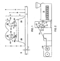
- an extruder 11 terminating in a slot-form die 13 extrudes a sheet of molten thermoplastic resin 14.
- the resin while moldable is lead into calender nip 16 formed between cooled mold roll 10 and pressure roll 18.
- the gap between rolls 10 and 18 sets the thickness T of the common layer 1 of thermoplastic, formed on the surface 10B of mold roll 10, see FIG. 2A .
- Mold cavities 10C formed in a pattern in the body of the mold roll have cavity portions defining the individual raised bases 2 and contiguous, deeper cavity portions shaped to form the fastener elements 5.
- the pressure of the calender nip ensures mold filling and production of an integrated structure, see FIG. 2B .
- the common layer 1, the pattern of individual raised bases 2, and the individual fastener elements 5 rising from mid regions of the raised bases are formed of thermoplastic resin that is continuous throughout the structure.
- thermoplastic continues on the cooled mold roll 10 until its form is set by cooling. Then, as a running web 20, it is pulled from the mold roll, led over further rolls indicated diagrammatically at 22, and as a finished web, 12, led to winder 24 or other processing station.
- the mold cavities are fixed, i.e. there are no relatively moving parts.
- the overhanging head portions 4A, 4B of the fastener are temporarily deformed.
- the mold roll comprises an axially aligned stack of alternating mold rings 10A and spacer rings 10B, each of which has planar radial faces.
- the face-to-face assembly of mold rings and spacer rings defines at the peripheries of the rings a cylindrical, exterior calender surface, which imparts the upper common surface 1A to the finished product, see FIG. 1B and 2A .
- Each mold ring 10A wherever a formation is desired, has a mold cavity 10C formed in its peripheral region. In a preferred form this cavity extends through the thickness of the mold ring 10A. In the assembly, this mold cavity is closed on each side by the planar radial faces of adjacent rings.
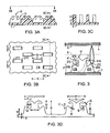
- Figs. 3-3D The embodiment of Figs. 3-3D is similar to that of FIG. 1 .
- Individual raised bases 2' rise from common portion 1'.
- the hook fastener elements 5' are of identical form to those of FIG. 1 .
- the upper surfaces 9'A and 9'B of the base are inclined at angle E of 45 degrees, steeper than in FIG. 1 , and resulting in a deeper depression adjacent the stem.
- the full set of dimensions for this specific embodiment is given in the preceding table.
- loops in commercial products may take many forms, and involve a considerable amount of irregularity and randomness, similar directing and diverting effects can occur with such products, to increase the likelihood of a given fastener element engaging a loop.
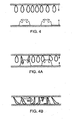
- Figs. 5-5D are views similar to those of FIGs. 1-1D for a pattern of individual raised bases supporting individual "J" form fastener hook elements 5".
- These are fastener elements having single head portions.
- the width J of the respective raised base is at least 45 percent wider than the width I of the stem at the raised base.
- the extra width of the base lies beneath the head overhang 6", and serves both to form a raised lower bound for the loop region 7", and forming a bend-resistant base for the fastener element 5".
- the lateral extent of the portion of the base relative to the J-form head may be the same as in FIG. 1 or FIG. 3 , for example.
- the specific embodiment of FIG. 5 is most similar to that of FIG. 1 .
- adjacent rows of J-form fastener elements have overhanging head portions projecting over their respective raised bases in opposite directions. Such an arrangement is shown in Figs. 5A , B and C.
- the embodiment of FIG. 5 can be manufactured by the calender molding system described, with similar advantages, or by other techniques such as those mentioned.
- the height H of the fastener elements 5, 5', 5" is less than about 0.015 inch (0.38 mm), often less than 0.010 inch (0.25 mm).
- the projected area of the fastener elements of a hook component is preferred for the projected area of the fastener elements of a hook component to occupy between about 10 percent and 25 percent of the respective area of the component.
- the spacing K of the fastening elements in the machine direction is selected at the time of forming the mold rings. After forming a set of mold rings of given thickness and element spacing, the fastener element density can still be varied by selection of the thickness L of the spacer rings disposed between adjacent mold rings, which determines the cross-machine spacing of the formations.
- Mold cavities for the raised bases and fastener elements may be formed through only a partial thickness of a mold ring, so that the mold cavity is open on only one radial side of the ring, where it is closed by the flat surface of an adjacent ring in the assembly, the adjacent ring being another mold ring or a spacer ring.
- Each mold cavity may instead be formed by mating mold portions in two face-to-face plates.
- a molded preform member may be formed having raised bases and stems protruding from portions of these bases. The stems, i.e.
- so-called "preform” elements may be of straight or inclined form, or have multiple branches, for instance diverging branches extending slightly in opposite directions from the vertical axis of the stem.
- the stems may be subjected to a post-molding operation in which a heated roll or other heating or shaping device causes the outer resin portions of the stems to form one or more head portions overlying the stem, and at least part of which overlies a portion of the raised base, to serve functions as have been described.
- a heated roll or other heating or shaping device causes the outer resin portions of the stems to form one or more head portions overlying the stem, and at least part of which overlies a portion of the raised base, to serve functions as have been described.
- an extrusion for instance having multiple extruded formations of the profiles of FIG. 1A , 3A or 5A , joined by a common layer, may be formed and subjected to cut and stretch action.
- an injection mold formed of a series of mold and spacer plates may form the fastener component integrally with a common surface of a larger object being injection molded.
Landscapes
- Engineering & Computer Science (AREA)
- Mechanical Engineering (AREA)
- Slide Fasteners, Snap Fasteners, And Hook Fasteners (AREA)
- Moulds For Moulding Plastics Or The Like (AREA)
Claims (18)
- Hakenkomponente zum Klettverschließen, die umfasst:einen sich seitlich erstreckenden allgemeinen Abschnitt (1) aus thermoplastischem Harz; undein Muster aus einzelnen im Wesentlichen erhöhten Basen bzw. Füßen (2), die über einen Bereich des allgemeinen Abschnitts verteilt sind und aus einem thermoplastischen Harz ausgebildet sind, das integral mit Harz des allgemeinen Abschnitts ist, wobei jeder erhöhte Fuß ein einzelnes Verschlusselement (5) trägt und seitlich von anderen erhöhten Füßen und ihren Verschlusselementen beabstandet ist, so daß der Schlingenraum, der sich über den allgemeinen Abschnitt erstreckt, im Wesentlichen jeden erhöhten Fuß (2) und sein Verschlusselement (5) umgibt;wobei jedes Verschlusselement (5) einen sich aufwärts erstreckenden Stiel (3) und einen Kopf (4), der mit dem Stiel verbunden ist, umfasst, wobei der Kopf sich seitlich über den Stiel hinaus in wenigstens eine Richtung erstreckt, um einen mit Schlingen in Eingriff bringbaren überhängenden Abschnitt, der in einer Spitze (6) endet, bereitzustellen, wobei das untere Ende des Stiels mit einem Abschnitt des jeweiligen erhöhten Fußes (2) verbunden ist; undwobei eine im Wesentlichen seitlich zusammenhängende obere Oberfläche (9) des erhöhten Fußes (2) unterhalb des überhängenden Abschnitts des jeweiligen Kopfs liegt und eine untere Grenze für einen Schlingenbereich (7) bildet, der direkt unterhalb des überhängenden Abschnitts des Verschlusselements liegt, wobeidie Spitze (6) des Kopfs und eine obere Oberfläche des erhöhten Fußes (2) zusammen einen beschränkten Durchgang (D) zu dem Schlingenbereich (7) bilden, dadurch gekennzeichnet, dass jedes Verschlusselement aus thermoplastischem Harz gebildet ist, das integral mit Harz des jeweilige erhöhten Fußes (2) ist, und die oberen Oberflächen (9) der erhöhten Füße (2) eine Vertiefung haben, die an den jeweiligen Stiel (3) angrenzt.
- Hakenkomponente nach Anspruch 1, dadurch gekennzeichnet, dass die Höhe (M) eines erhöhten Fußes (2) relativ zu dem allgemeinen Abschnitt (1) zwischen etwa 40 Prozent und 100 Prozent der Höhe (H) des jeweiligen Verschlusselements (5) über dessen erhöhtem Fuß ist.
- Hakenkomponente nach Anspruch 1 oder Anspruch 2, dadurch gekennzeichnet, dass der Abstand (D) zwischen der Spitze (6) des überhängenden Kopfabschnitts und dem nächstgelegenen Abschnitt der oberen Oberfläche (9) des jeweiligen erhöhten Fußes weniger als etwa 50 Prozent der Erhöhung der (B) der Spitze relativ zu dem allgemeinen Abschnitt (1), der seitlich außerhalb des erhöhten Fußes liegt, ist.
- Hakenkomponente nach einem der vorstehenden Ansprüche, dadurch gekennzeichnet, dass die Oberflächen des Verschlusselements (5) und des erhöhten Fußes (2) derart geformt sind, dass ein Teil des Schlingenabschnitts (7) seitlich einwärts von der Spitze (6) in Richtung des Stiels (3) angeordnet ist.
- Hakenkomponente nach Anspruch 4, dadurch gekennzeichnet, dass die Oberfläche des Stiels (3), die zu dem Schlingenbereich (7) freiliegt, nicht weiter als 30 Grad zu der Senkrechten auf die seitliche Richtung geneigt ist, wobei der Stiel in einer im Wesentlichen seitlich ausgesparten Beziehung zu der Spitze (6) des Körperabschnitts (4) angeordnet ist.
- Hakenkomponente nach einem der vorstehenden Ansprüche, dadurch gekennzeichnet, dass die oberen Oberflächen (9) der erhöhten Füße (2) in einem Neigungswinkel zwischen etwa 10 und 60 Grad relativ zu der Seitenrichtung nach unten in die Richtung der jeweiligen Stiele (3) geneigt sind.
- Hakenkomponente nach einem der vorstehenden Ansprüche, dadurch gekennzeichnet, dass der Stiel (3) jedes Verschlusselements (5) und des jeweiligen erhöhten Fußes (2) beide geformte koplanare Seitenoberflächen haben.
- Hakenkomponente nach einem der vorstehenden Ansprüche, dadurch gekennzeichnet, dass jedes Verschlusselement (5) einen Kopf (4) hat, der im Wesentlichen in zwei entgegengesetzte seitliche Richtungen vorsteht und dass jeder überhängende Abschnitt über einem Abschnitt des jeweiligen erhöhten Fußes (2) liegt, wobei erhöhte obere Oberflächen (9) dieser Abschnitte des erhöhten Fußes Untergrenzen für Schlaufenabschnitte bilden, die unterhalb der überhängenden Köpfe des Verschlusselements liegen.
- Hakenkomponente nach Anspruch 8, dadurch gekennzeichnet, dass die Breite (J) des jeweiligen erhöhten Fußes (2) in einer Ebene der überhängenden Abschnitte jedes Verschlusselements (5) wenigstens 60 Prozent breiter als die Breite (I) des Stiels (3) an dem erhöhten Fuß ist.
- Hakenkomponente nach einem der Ansprüche 1 - 7, dadurch gekennzeichnet, dass jedes Verschlusselement (5) nur einen überhängenden Abschnitt hat, und wobei die Verschlusselemente in benachbarten Reihen angeordnet sind, wobei die Verschlusselemente (5) einer Reihe überhängende Abschnitte haben, die alle in einer seitlichen Richtung über ihre jeweiligen erhöhten Füße (2) vorstehen, und die Verschlusselemente einer benachbarten Reihe überhängende Abschnitte haben, von denen alle in der entgegengesetzten seitlichen Richtung über Abschnitte ihrer jeweiligen erhöhten Füße (2) vorstehen.
- Hakenkomponente nach Anspruch 10, dadurch gekennzeichnet, dass die Breite (J) des jeweiligen erhöhten Fußes in der Ebene des überhängenden Abschnitts eines Verschlusselementes (5) wenigstens 45 Prozent breiter als die Breite (I) des Stiels an dem erhöhten Fuß ist.
- Hakenkomponente nach einem der vorhergehenden Ansprüche, dadurch gekennzeichnet, dass der vorstehende Bereich der Verschlusselemente zwischen etwa 10 Prozent und 25 Prozent der jeweiligen Fläche der Hakenkomponente einnimmt.
- Hakenkomponente nach einem der vorstehenden Ansprüche, dadurch gekennzeichnet, dass die Elemente des Verschlusses (5) von ihren jeweiligen erhöhten Füßen (2) gemessen eine Höhe (H) von weniger als etwa 0,015 Inch (0,38 mm) haben.
- Hakenkomponente nach einem der vorstehenden Ansprüche, dadurch gekennzeichnet, dass das seitliche äußerste Ende eines seitlich zusammenhängenden Abschnitts des erhöhten Fußes (2) in einem seitlichen Abstand (P) von dem Stiel (3) des Verschlusselements (5) liegt, der nicht größer als 175 Prozent des seitlichen Abstands (Q) von der Spitze (6) des überhängenden Abschnitts zu dem Stiel (3) ist.
- Verfahren zum Ausbilden der Hakenkomponente nach einem der vorstehenden Ansprüche, wobei das Verfahren umfasst:Bereitstellen einer Form (10), die eine Anordnung fester Formhohlräume (10C) mit Hohlraumabschnitten, um die erhöhten Füße auszubilden, und zusammenhängenden tieferen Hohlraumabschnitten, die geformt sind, um die Verschlusselemente auszubilden, definiert,Füllen der Formhohlräume mit thermoplastischem Harz, während ein sich seitlich erstreckender gemeinsamer Abschnitt aus dem Harz über den Eingängen aller Formhohlräume und über einer freiliegenden Oberfläche (10B) der sich zwischen den Hohlräumen erstreckenden Form liegt, undKühlen des Harzes, bis die Formen der Füße (2) und Verschlusselemente (5) ausgebildet sind, und Entformen des Verschlusses, was das Ziehen der Verschlusselemente durch die Hohlraumabschnitte, welche die jeweiligen erhöhten Füße bilden, beinhaltet.
- Verfahren nach Anspruch 15, dadurch gekennzeichnet, dass die Formhohlraumabschnitte für die einzelnen Füße (2) und die jeweiligen Verschlusselemente (5) in einer Formwalze (10) ausgebildet werden und dass das thermoplastische Harz (14) eingeleitet wird, indem ein Kalanderwalzenspalt (16) mit der Formwalze und einer benachbarten Druckwalze (18) gebildet wird und dass das Verfahren das Einleiten von erhitztem Harz zu dem Walzenspalt, während die Walzen sich gemeinsam drehen, beinhaltet.
- Verfahren nach Anspruch 16, dadurch gekennzeichnet, dass die Formhohlräume als eine Reihe von Hohlräumen in den Umfängen einer Vielzahl von Ringen (10A) ausgebildet sind, und dass die Formwalze (10) montiert wird, indem Ringe in einer axial ausgerichteten Anordnung gestapelt werden.
- Verfahren nach Anspruch 17, dadurch gekennzeichnet, dass es Ringe (10A) der Formwalze gibt, die flache Seiten benachbart zu den Seiten der in anderen Formringen ausgebildeten Formhohlräume (10C) haben und diese ausbilden, wobei Seiten der Verschlusselemente (5) und der jeweiligen erhöhten Füße (2) koplanar sind.
Priority Applications (1)
| Application Number | Priority Date | Filing Date | Title |
|---|---|---|---|
| EP10011257A EP2332434A1 (de) | 2005-03-11 | 2006-03-13 | Komponenten eines Klettverschluss sowie Herstellungsverfahren |
Applications Claiming Priority (1)
| Application Number | Priority Date | Filing Date | Title |
|---|---|---|---|
| US11/078,174 US7516524B2 (en) | 2005-03-11 | 2005-03-11 | Hook fastener components and methods of their manufacture |
Related Child Applications (1)
| Application Number | Title | Priority Date | Filing Date |
|---|---|---|---|
| EP10011257.2 Division-Into | 2010-09-28 |
Publications (3)
| Publication Number | Publication Date |
|---|---|
| EP1700532A2 EP1700532A2 (de) | 2006-09-13 |
| EP1700532A3 EP1700532A3 (de) | 2007-07-25 |
| EP1700532B1 true EP1700532B1 (de) | 2011-01-19 |
Family
ID=36522187
Family Applications (2)
| Application Number | Title | Priority Date | Filing Date |
|---|---|---|---|
| EP10011257A Withdrawn EP2332434A1 (de) | 2005-03-11 | 2006-03-13 | Komponenten eines Klettverschluss sowie Herstellungsverfahren |
| EP06005100A Expired - Lifetime EP1700532B1 (de) | 2005-03-11 | 2006-03-13 | Komponenten eines Klettverschluss sowie Herstellungsverfahren |
Family Applications Before (1)
| Application Number | Title | Priority Date | Filing Date |
|---|---|---|---|
| EP10011257A Withdrawn EP2332434A1 (de) | 2005-03-11 | 2006-03-13 | Komponenten eines Klettverschluss sowie Herstellungsverfahren |
Country Status (5)
| Country | Link |
|---|---|
| US (1) | US7516524B2 (de) |
| EP (2) | EP2332434A1 (de) |
| CN (1) | CN1854544B (de) |
| DE (1) | DE602006019655D1 (de) |
| ES (1) | ES2359012T3 (de) |
Cited By (1)
| Publication number | Priority date | Publication date | Assignee | Title |
|---|---|---|---|---|
| WO2014128201A1 (en) * | 2013-02-22 | 2014-08-28 | Velcro Industries B.V. | Touch fastener structures |
Families Citing this family (41)
| Publication number | Priority date | Publication date | Assignee | Title |
|---|---|---|---|---|
| US7493676B2 (en) * | 2006-04-13 | 2009-02-24 | Ykk Corporation | Hook fastener structures |
| US20080178436A1 (en) * | 2007-01-25 | 2008-07-31 | 3M Innovative Properties Company | Fastener webs with microstructured particles and methods of making same |
| DE102008031251B3 (de) * | 2008-07-02 | 2010-04-15 | Hölzel Stanz- und Feinwerktechnik GmbH & Co. KG | Halterungsvorrichtung |
| TWI370726B (en) * | 2008-10-21 | 2012-08-21 | Taiwan Paiho Ltd | Fastening strap and manufacturing method thereof |
| GB0905132D0 (en) | 2009-03-25 | 2009-05-06 | Airbus Uk Ltd | Profile of interfacing projections |
| FR2945413B1 (fr) * | 2009-05-15 | 2011-05-06 | Aplix Sa | Element d'accrochage pour former la partie male d'un auto-agrippant |
| WO2011094474A1 (en) | 2010-01-29 | 2011-08-04 | Velcro Industries B.V. | Temporary surface protection |
| US8424172B2 (en) | 2010-04-27 | 2013-04-23 | Velcro Industries B.V. | Male touch fastener element |
| US8851440B2 (en) | 2010-09-29 | 2014-10-07 | Velcro Industries B.V. | Releasable hanging system |
| CA2818317C (en) | 2010-11-17 | 2018-10-30 | Velcro Industries B.V. | Touch fastening product face configuration |
| US9084701B2 (en) | 2011-11-10 | 2015-07-21 | The Procter & Gamble Company | Absorbent articles with hook and loop fastening systems |
| US20140000784A1 (en) | 2012-06-29 | 2014-01-02 | Shrish Yashwant Rane | Method for Producing a Multi-Layer Nonwoven Web Having Enhanced Mechanical Properties |
| US20140000070A1 (en) | 2012-06-29 | 2014-01-02 | Arman Ashraf | Fastening System Having Multicomponent Fiber Component Providing Enhanced Separation Resistance |
| US9056032B2 (en) | 2012-06-29 | 2015-06-16 | The Procter & Gamble Company | Wearable article with outwardmost layer of multicomponent fiber nonwoven providing enhanced mechanical features |
| WO2014060367A2 (en) * | 2012-10-15 | 2014-04-24 | Velcro Industries B.V. | Double-sided fasteners |
| US9668595B2 (en) | 2013-06-03 | 2017-06-06 | 3M Innovative Properties Company | Removable wall decoration kits, systems and methods |
| USD741069S1 (en) | 2014-03-06 | 2015-10-20 | 3M Innovative Properties Company | Decorative display base |
| USD739661S1 (en) | 2014-03-06 | 2015-09-29 | 3M Innovative Properties Company | Decorative display |
| USD742124S1 (en) | 2014-03-06 | 2015-11-03 | 3M Innovative Properties Company | Decorative display |
| WO2016007892A1 (en) * | 2014-07-10 | 2016-01-14 | Velcro Industries B.V. | Printing plate connection systems |
| USD756135S1 (en) | 2015-03-05 | 2016-05-17 | 3M Innovative Properties Company | Display base |
| USD776942S1 (en) | 2015-03-19 | 2017-01-24 | 3M Innovative Properties Company | Display base |
| USD746600S1 (en) | 2015-03-19 | 2016-01-05 | 3M Innovative Properties Company | Display base |
| USD746601S1 (en) | 2015-03-19 | 2016-01-05 | 3M Innovative Properties Company | Display base |
| USD746599S1 (en) | 2015-03-19 | 2016-01-05 | 3M Innovative Properties Company | Display base |
| USD746602S1 (en) | 2015-03-19 | 2016-01-05 | 3M Innovative Properties Company | Display base |
| USD747888S1 (en) | 2015-03-19 | 2016-01-26 | 3M Innovative Properties Company | Display base |
| USD747110S1 (en) | 2015-03-19 | 2016-01-12 | 3M Innovative Properties Company | Display base |
| USD746603S1 (en) | 2015-03-26 | 2016-01-05 | 3M Innovative Properties Company | Display base |
| US11089845B2 (en) | 2015-12-24 | 2021-08-17 | Ykk Corporation | Molded surface fastener |
| CN108430251B (zh) * | 2015-12-24 | 2022-03-01 | Ykk株式会社 | 成形面连接件 |
| US10349707B2 (en) * | 2016-07-05 | 2019-07-16 | Alfatex Nv | Fastener tape |
| WO2018150493A1 (ja) * | 2017-02-15 | 2018-08-23 | Ykk株式会社 | 成形面ファスナー及び成形面ファスナーの製造方法、並びに成形装置 |
| WO2018185818A1 (ja) | 2017-04-03 | 2018-10-11 | Ykk株式会社 | 成形装置、成形面ファスナーの製造方法、及び成形面ファスナー |
| EP3651605B1 (de) | 2017-07-11 | 2021-01-13 | Velcro Bvba | Herstellung von befestigungselementen |
| JP2021500177A (ja) | 2017-10-27 | 2021-01-07 | スリーエム イノベイティブ プロパティズ カンパニー | 繰り返し着脱可能なファスナーフックのための前駆体ウェブ及び製造方法 |
| CN109349747B (zh) * | 2018-11-20 | 2024-05-31 | 浙江鸿明织带有限公司 | 一种高强度可靠型粘扣带 |
| US12421638B2 (en) * | 2019-02-28 | 2025-09-23 | Velcro Ip Holdings Llc | Making soft fabric touch fasteners |
| DE102020007585A1 (de) * | 2020-12-11 | 2022-06-15 | Gottlieb Binder Gmbh & Co. Kg | Verschlussteil |
| JP7596563B2 (ja) * | 2021-08-04 | 2024-12-09 | Ykk株式会社 | フック・トゥ・フックファスナ |
| WO2024020924A1 (en) | 2022-07-28 | 2024-02-01 | The Procter & Gamble Company | Absorbent article with fastening component for disposal |
Citations (1)
| Publication number | Priority date | Publication date | Assignee | Title |
|---|---|---|---|---|
| WO1994022338A1 (en) * | 1993-04-07 | 1994-10-13 | The Procter & Gamble Company | Process and manufacture for refastenable mechanical fastening system attached to substrate protrusion |
Family Cites Families (50)
| Publication number | Priority date | Publication date | Assignee | Title |
|---|---|---|---|---|
| US3557407A (en) * | 1968-08-19 | 1971-01-26 | Jerome H Lemelson | Apparatus for surface forming sheet material |
| FR2116704A5 (de) | 1970-12-04 | 1972-07-21 | Velcro France | |
| ES453167A1 (es) | 1976-11-10 | 1977-11-16 | Velero Espanola S A | Mejoras en los procedimientos de fabricacion continua de e- lementos monobloques autofijables. |
| US4794028A (en) | 1984-04-16 | 1988-12-27 | Velcro Industries B.V. | Method for continuously producing a multi-hook fastner member and product of the method |
| US4872243A (en) | 1984-04-16 | 1989-10-10 | Velcro Industries B.V. | Multi-hook fastener member |
| US5144786A (en) | 1988-01-26 | 1992-09-08 | Tac-Fast Systems Sa | Anchor board system |
| US4984339A (en) | 1988-10-20 | 1991-01-15 | Velcro Industries B.V. | Hook for hook and loop fasteners |
| US5540673A (en) | 1989-01-31 | 1996-07-30 | The Procter & Gamble Company | Refastenable mechanical fastening system |
| US5180534A (en) | 1990-12-21 | 1993-01-19 | The Procter & Gamble Company | Process of manufacturing a refastenable mechanical fastening system |
| FI95643C (fi) | 1989-01-31 | 1996-03-11 | Procter & Gamble | Menetelmä tuottaa kiinnitysjärjestelmä |
| US5230851A (en) | 1989-01-31 | 1993-07-27 | The Procter & Gamble Company | Process of manufacturing a refastenable mechanical fastening system |
| JPH0355716U (de) | 1989-10-03 | 1991-05-29 | ||
| US5116563A (en) | 1990-06-28 | 1992-05-26 | The Procter & Gamble Company | Process for producing a mechanical fastener |
| JPH0431512U (de) | 1990-07-03 | 1992-03-13 | ||
| JP2545058Y2 (ja) | 1990-07-03 | 1997-08-25 | ワイケイケイ株式会社 | フック片を一体成形した合成樹脂製面ファスナー用係着部材 |
| US5260015A (en) | 1991-08-16 | 1993-11-09 | Velcro Industries, B.V. | Method for making a laminated hook fastener |
| US5235731A (en) | 1992-03-26 | 1993-08-17 | Kuraray Co., Ltd. | Molded-resin separable fastener and fastening system utilizing the same |
| JPH0584213U (ja) | 1992-04-24 | 1993-11-16 | 吉田工業株式会社 | 一体成形面ファスナー |
| US5315740A (en) | 1992-08-20 | 1994-05-31 | Velcro Industries, B.V. | Hook for hook and loop fasteners |
| US5325569A (en) | 1992-10-30 | 1994-07-05 | The Procter & Gamble Company | Refastenable mechanical fastening system having particular viscosity and rheology characteristics |
| US5392498A (en) | 1992-12-10 | 1995-02-28 | The Proctor & Gamble Company | Non-abrasive skin friendly mechanical fastening system |
| US5318740A (en) * | 1992-12-21 | 1994-06-07 | Abc Group | Extrusion blow molding an automotive boot |
| US5692517A (en) * | 1993-01-06 | 1997-12-02 | Junker; Andrew | Brain-body actuated system |
| US5720740A (en) * | 1993-04-07 | 1998-02-24 | The Procter & Gamble Company | Refastenable mechanical fastening system attached to substrate protrusion |
| NL9301218A (nl) | 1993-07-12 | 1995-02-01 | Vuuren Johannes Van | Inrichting voor het snijden van één of meer graszoden en werkwijze voor het stapelen daarvan. |
| JP2731103B2 (ja) | 1993-09-08 | 1998-03-25 | ワイケイケイ株式会社 | 一体成形面ファスナー |
| JP2854222B2 (ja) | 1993-09-14 | 1999-02-03 | ワイケイケイ株式会社 | 一体成形面ファスナーのフック片構造 |
| JP2886455B2 (ja) | 1994-07-08 | 1999-04-26 | ワイケイケイ株式会社 | 一体成形面ファスナーの係着片構造 |
| JP3474644B2 (ja) * | 1994-08-26 | 2003-12-08 | Ykk株式会社 | 一体成形面ファスナー |
| JP2886458B2 (ja) * | 1994-08-26 | 1999-04-26 | ワイケイケイ株式会社 | 一体成形面ファスナー |
| JP3183785B2 (ja) | 1994-10-24 | 2001-07-09 | ワイケイケイ株式会社 | 一体成形面ファスナーのフック片構造 |
| JP3093938B2 (ja) | 1994-11-01 | 2000-10-03 | ワイケイケイ株式会社 | 一体成形面ファスナーのフック片構造 |
| JP3474688B2 (ja) | 1994-12-02 | 2003-12-08 | Ykk株式会社 | 一体成形面ファスナー |
| JP3308417B2 (ja) * | 1995-02-28 | 2002-07-29 | ワイケイケイ株式会社 | 成形面ファスナーのフック片構造 |
| US5692271A (en) | 1995-03-07 | 1997-12-02 | Velcro Industries B.V. | Enhanced flexibility fastener, method and apparatus for its making, and product incorporating it |
| US5620769A (en) | 1995-05-02 | 1997-04-15 | Ykk Corporation | Molded surface fastener and method for manufacturing the same |
| JPH08322609A (ja) | 1995-06-02 | 1996-12-10 | Ykk Kk | 成形面ファスナー及びその製造方法 |
| JPH09315A (ja) * | 1995-06-20 | 1997-01-07 | Ykk Kk | 成形面ファスナー及びその製造方法 |
| JP3494529B2 (ja) | 1996-06-06 | 2004-02-09 | Ykk株式会社 | 一体成形面ファスナー |
| US5900350A (en) | 1996-06-06 | 1999-05-04 | Velcro Industries B.V. | Molding methods, molds and products |
| US5887320A (en) | 1997-03-21 | 1999-03-30 | Velcro Industries B.V. | Fastener component with flexible fastener members |
| JPH1142249A (ja) * | 1997-07-25 | 1999-02-16 | Ykk Corp | 使い捨ておむつとその廃棄時の折り畳み固定方法 |
| US5884374A (en) | 1997-11-20 | 1999-03-23 | Velcro Industries B.V. | Fastener members and apparatus for their fabrication |
| WO1999060881A1 (en) | 1998-05-26 | 1999-12-02 | Kao Corporation | Fastener and absorbing article using it |
| US6224807B1 (en) | 1999-03-25 | 2001-05-01 | Velcro Industries B.V. | Methods of molding fasteners and of forming fastener molds |
| US6303062B1 (en) * | 1999-04-13 | 2001-10-16 | 3M Innovative Properties Company | Mechanical fastener and method for making the same |
| US6543099B1 (en) * | 2000-06-02 | 2003-04-08 | Velcro Industries B.V. | Varying the loop engageability of fastener element arrays |
| AU2002240162B2 (en) * | 2001-01-31 | 2006-07-20 | Velcro BVBA | Direct hook engagement |
| US6996880B2 (en) | 2003-04-01 | 2006-02-14 | Velcro Industries B.V. | Fastener elements and methods of manufacture |
| USD516952S1 (en) * | 2003-07-10 | 2006-03-14 | Velcro Industries B.V. | Touch fastener element |
-
2005
- 2005-03-11 US US11/078,174 patent/US7516524B2/en not_active Expired - Lifetime
-
2006
- 2006-03-13 ES ES06005100T patent/ES2359012T3/es not_active Expired - Lifetime
- 2006-03-13 DE DE602006019655T patent/DE602006019655D1/de not_active Expired - Lifetime
- 2006-03-13 EP EP10011257A patent/EP2332434A1/de not_active Withdrawn
- 2006-03-13 CN CN200610073917XA patent/CN1854544B/zh not_active Expired - Fee Related
- 2006-03-13 EP EP06005100A patent/EP1700532B1/de not_active Expired - Lifetime
Patent Citations (1)
| Publication number | Priority date | Publication date | Assignee | Title |
|---|---|---|---|---|
| WO1994022338A1 (en) * | 1993-04-07 | 1994-10-13 | The Procter & Gamble Company | Process and manufacture for refastenable mechanical fastening system attached to substrate protrusion |
Cited By (2)
| Publication number | Priority date | Publication date | Assignee | Title |
|---|---|---|---|---|
| WO2014128201A1 (en) * | 2013-02-22 | 2014-08-28 | Velcro Industries B.V. | Touch fastener structures |
| US9918525B2 (en) | 2013-02-22 | 2018-03-20 | Velcro BVBA | Touch fastener structures |
Also Published As
| Publication number | Publication date |
|---|---|
| ES2359012T3 (es) | 2011-05-17 |
| US20060200951A1 (en) | 2006-09-14 |
| EP1700532A2 (de) | 2006-09-13 |
| EP2332434A1 (de) | 2011-06-15 |
| CN1854544A (zh) | 2006-11-01 |
| EP1700532A3 (de) | 2007-07-25 |
| US7516524B2 (en) | 2009-04-14 |
| CN1854544B (zh) | 2011-04-06 |
| DE602006019655D1 (de) | 2011-03-03 |
Similar Documents
| Publication | Publication Date | Title |
|---|---|---|
| EP1700532B1 (de) | Komponenten eines Klettverschluss sowie Herstellungsverfahren | |
| CN1188062C (zh) | 钩形紧固元件及其制造方法 | |
| US7181812B2 (en) | Fastener elements and methods of manufacture | |
| EP1060068B1 (de) | Nachgeformte köpfe auf verschlusselementen | |
| CN110868883B (zh) | 形成紧固件元件 | |
| US6162040A (en) | Molds for forming touch fasteners | |
| US20030127769A1 (en) | Fastener members and apparatus for their fabrication | |
| US20040031130A1 (en) | Hook and loop fastener | |
| CN1231584A (zh) | 用于机械式搭扣的j形钩钩条 | |
| KR20180080289A (ko) | 성형 면 파스너, 성형 면 파스너의 제조 방법 및 성형 장치 | |
| CN120857885A (zh) | 阳型接触紧固件元件 | |
| US20100101056A1 (en) | Method for making mushroom-type hook strap and mushroom-type hook strap made thereby | |
| EP2944217A1 (de) | Verfahren zur herstellung einer pilzartigen hakenband und dadurch hergestellte hakenband | |
| AU2008230017A1 (en) | Method for making mushroom-type hook strap and mushroom-type hook strap made thereby | |
| CN110312448A (zh) | 成形面连接件和成形面连接件的制造方法、以及成形装置 | |
| HK1003360A1 (en) | Molded surface fastener |
Legal Events
| Date | Code | Title | Description |
|---|---|---|---|
| PUAI | Public reference made under article 153(3) epc to a published international application that has entered the european phase |
Free format text: ORIGINAL CODE: 0009012 |
|
| 17P | Request for examination filed |
Effective date: 20060330 |
|
| AK | Designated contracting states |
Kind code of ref document: A2 Designated state(s): AT BE BG CH CY CZ DE DK EE ES FI FR GB GR HU IE IS IT LI LT LU LV MC NL PL PT RO SE SI SK TR |
|
| AX | Request for extension of the european patent |
Extension state: AL BA HR MK YU |
|
| PUAL | Search report despatched |
Free format text: ORIGINAL CODE: 0009013 |
|
| AK | Designated contracting states |
Kind code of ref document: A3 Designated state(s): AT BE BG CH CY CZ DE DK EE ES FI FR GB GR HU IE IS IT LI LT LU LV MC NL PL PT RO SE SI SK TR |
|
| AX | Request for extension of the european patent |
Extension state: AL BA HR MK YU |
|
| 17Q | First examination report despatched |
Effective date: 20071025 |
|
| AKX | Designation fees paid |
Designated state(s): DE ES GB |
|
| GRAP | Despatch of communication of intention to grant a patent |
Free format text: ORIGINAL CODE: EPIDOSNIGR1 |
|
| GRAS | Grant fee paid |
Free format text: ORIGINAL CODE: EPIDOSNIGR3 |
|
| GRAA | (expected) grant |
Free format text: ORIGINAL CODE: 0009210 |
|
| AK | Designated contracting states |
Kind code of ref document: B1 Designated state(s): DE ES GB |
|
| REG | Reference to a national code |
Ref country code: GB Ref legal event code: FG4D |
|
| REF | Corresponds to: |
Ref document number: 602006019655 Country of ref document: DE Date of ref document: 20110303 Kind code of ref document: P |
|
| REG | Reference to a national code |
Ref country code: DE Ref legal event code: R096 Ref document number: 602006019655 Country of ref document: DE Effective date: 20110303 |
|
| REG | Reference to a national code |
Ref country code: ES Ref legal event code: FG2A Ref document number: 2359012 Country of ref document: ES Kind code of ref document: T3 Effective date: 20110517 |
|
| PLBE | No opposition filed within time limit |
Free format text: ORIGINAL CODE: 0009261 |
|
| STAA | Information on the status of an ep patent application or granted ep patent |
Free format text: STATUS: NO OPPOSITION FILED WITHIN TIME LIMIT |
|
| 26N | No opposition filed |
Effective date: 20111020 |
|
| REG | Reference to a national code |
Ref country code: DE Ref legal event code: R097 Ref document number: 602006019655 Country of ref document: DE Effective date: 20111020 |
|
| REG | Reference to a national code |
Ref country code: GB Ref legal event code: 732E Free format text: REGISTERED BETWEEN 20160526 AND 20160601 |
|
| REG | Reference to a national code |
Ref country code: DE Ref legal event code: R081 Ref document number: 602006019655 Country of ref document: DE Owner name: VELCRO IP HOLDINGS LLC, MANCHESTER, US Free format text: FORMER OWNER: VELCRO INDUSTRIES B.V., CURACAO, AN Ref country code: DE Ref legal event code: R082 Ref document number: 602006019655 Country of ref document: DE Representative=s name: FISH & RICHARDSON P.C., DE Ref country code: DE Ref legal event code: R082 Ref document number: 602006019655 Country of ref document: DE Representative=s name: MUELLER-BORE & PARTNER PATENTANWAELTE PARTG MB, DE Ref country code: DE Ref legal event code: R081 Ref document number: 602006019655 Country of ref document: DE Owner name: VELCRO BVBA, BE Free format text: FORMER OWNER: VELCRO INDUSTRIES B.V., CURACAO, AN |
|
| REG | Reference to a national code |
Ref country code: ES Ref legal event code: PC2A Owner name: VELCRO BVBA Effective date: 20160705 |
|
| REG | Reference to a national code |
Ref country code: GB Ref legal event code: 732E Free format text: REGISTERED BETWEEN 20210211 AND 20210217 Ref country code: ES Ref legal event code: PC2A Owner name: VELCRO IP HOLDINGS LLC Effective date: 20210304 |
|
| REG | Reference to a national code |
Ref country code: DE Ref legal event code: R082 Ref document number: 602006019655 Country of ref document: DE Representative=s name: FISH & RICHARDSON P.C., DE Ref country code: DE Ref legal event code: R081 Ref document number: 602006019655 Country of ref document: DE Owner name: VELCRO IP HOLDINGS LLC, MANCHESTER, US Free format text: FORMER OWNER: VELCRO BVBA, DEINZE, BE |
|
| P01 | Opt-out of the competence of the unified patent court (upc) registered |
Effective date: 20230817 |
|
| PGFP | Annual fee paid to national office [announced via postgrant information from national office to epo] |
Ref country code: GB Payment date: 20240222 Year of fee payment: 19 |
|
| PGFP | Annual fee paid to national office [announced via postgrant information from national office to epo] |
Ref country code: ES Payment date: 20240404 Year of fee payment: 19 |
|
| PGFP | Annual fee paid to national office [announced via postgrant information from national office to epo] |
Ref country code: DE Payment date: 20250319 Year of fee payment: 20 |
|
| GBPC | Gb: european patent ceased through non-payment of renewal fee |
Effective date: 20250313 |
|
| PG25 | Lapsed in a contracting state [announced via postgrant information from national office to epo] |
Ref country code: GB Free format text: LAPSE BECAUSE OF NON-PAYMENT OF DUE FEES Effective date: 20250313 |
|
| REG | Reference to a national code |
Ref country code: DE Ref legal event code: R071 Ref document number: 602006019655 Country of ref document: DE |
|
| REG | Reference to a national code |
Ref country code: ES Ref legal event code: FD2A Effective date: 20260428 |