EP1700556B1 - System und Verfahren zur Erhöhung der Trägheit in einer Turbinenbürste - Google Patents
System und Verfahren zur Erhöhung der Trägheit in einer Turbinenbürste Download PDFInfo
- Publication number
- EP1700556B1 EP1700556B1 EP05356161.9A EP05356161A EP1700556B1 EP 1700556 B1 EP1700556 B1 EP 1700556B1 EP 05356161 A EP05356161 A EP 05356161A EP 1700556 B1 EP1700556 B1 EP 1700556B1
- Authority
- EP
- European Patent Office
- Prior art keywords
- turbine
- brush
- blades
- brush member
- inertia
- Prior art date
- Legal status (The legal status is an assumption and is not a legal conclusion. Google has not performed a legal analysis and makes no representation as to the accuracy of the status listed.)
- Expired - Lifetime
Links
Images



Classifications
-
- G—PHYSICS
- G01—MEASURING; TESTING
- G01N—INVESTIGATING OR ANALYSING MATERIALS BY DETERMINING THEIR CHEMICAL OR PHYSICAL PROPERTIES
- G01N33/00—Investigating or analysing materials by specific methods not covered by groups G01N1/00 - G01N31/00
- G01N33/48—Biological material, e.g. blood, urine; Haemocytometers
- G01N33/50—Chemical analysis of biological material, e.g. blood, urine; Testing involving biospecific ligand binding methods; Immunological testing
- G01N33/66—Chemical analysis of biological material, e.g. blood, urine; Testing involving biospecific ligand binding methods; Immunological testing involving blood sugars, e.g. galactose
-
- A—HUMAN NECESSITIES
- A47—FURNITURE; DOMESTIC ARTICLES OR APPLIANCES; COFFEE MILLS; SPICE MILLS; SUCTION CLEANERS IN GENERAL
- A47L—DOMESTIC WASHING OR CLEANING; SUCTION CLEANERS IN GENERAL
- A47L9/00—Details or accessories of suction cleaners, e.g. mechanical means for controlling the suction or for effecting pulsating action; Storing devices specially adapted to suction cleaners or parts thereof; Carrying-vehicles specially adapted for suction cleaners
- A47L9/02—Nozzles
- A47L9/04—Nozzles with driven brushes or agitators
- A47L9/0405—Driving means for the brushes or agitators
- A47L9/0416—Driving means for the brushes or agitators driven by fluid pressure, e.g. by means of an air turbine
-
- A—HUMAN NECESSITIES
- A61—MEDICAL OR VETERINARY SCIENCE; HYGIENE
- A61B—DIAGNOSIS; SURGERY; IDENTIFICATION
- A61B5/00—Measuring for diagnostic purposes; Identification of persons
- A61B5/145—Measuring characteristics of blood in vivo, e.g. gas concentration or pH-value ; Measuring characteristics of body fluids or tissues, e.g. interstitial fluid or cerebral tissue
- A61B5/14532—Measuring characteristics of blood in vivo, e.g. gas concentration or pH-value ; Measuring characteristics of body fluids or tissues, e.g. interstitial fluid or cerebral tissue for measuring glucose, e.g. by tissue impedance measurement
Definitions
- the present invention relates generally to the field of vacuum cleaners and the like.
- a turbine brush of a vacuum cleaner is rotated by a turbine to remove impurities on a surface being cleaned.
- vacuum cleaners comprise a brush member that contacts the surface being cleaned to draw in dust from the surface. Moving along the surface being cleaned, the brush member is typically rotated to scratch or beat the surface being cleaned, thereby separating the dust from the surface being cleaned. The separated dust is drawn into a main body of the vacuum cleaner by a suction force generated in the main body.
- the brush member is typically rotated by a dedicated driving motor.
- the driving motor is mounted in connection with the brush member to selectively rotate the brush member.
- connection between the driving motor and the brush member increases the complexity of the structure and increases manufacturing costs. Therefore, recently, a turbine unit has been introduced to rotate the brush member.
- the turbine unit In structures that employ a turbine unit to rotate the brush member, the turbine unit is mounted on a suction path through which the dust is drawn in by the suction force generated in the main body.
- the turbine unit is rotated by air drawn in through the suction path, and the rotating force is supplied to the brush member through a belt. Accordingly, the brush member draws in dust while rotating in contact with the surface being cleaned.
- the dust drawn in through the suction path may be caught in the turbine unit.
- small particles such as hair and fine dust are caught in the turbine unit, the resulting friction may decrease the rotation of the turbine due to low inertia and low torque of the turbine unit.
- AT-B-383 264 discloses a brush for a vacuum cleaner which comprises a brush body, a brush member mounted so as to oscillate relative to the brush body and a turbine rotated by air drawn in through a suction path of the brush body.
- the turbine is mechanically associated with a dynamo and the movement of the brush member is activated by an electromagnetic device which is electrically coupled with the dynamo.
- the brush member is not rotatably mounted to the brush body, it can only oscillate relative to the brush body.
- JP-A-06 105772 and DE-C-196 02 406 each disclose a brush for a vacuum cleaner, comprising a brush member which is rotatably mounted to a brush body and driven by a turbine rotated by air drawn in through a suction path of the brush body.
- the turbine disclosed in JP-A-06 105772 has blades with a globally constant shape along their length, whereas the blades of the turbine disclosed in DE-C-196 02 406 extend only in the vicinity of the outermost circumference of the turbine, not from the rotational center of the turbine. Such turbine structures do not lead to an optimal rotative force of the brush member.
- the present invention may solve one or more of the above problems and/or disadvantages and may provide one or more of the advantages described herein.
- a turbine brush for a vacuum cleaner according to claim 1 is provided.
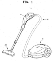
- FIG. 1 is a perspective view of a vacuum cleaner employing a turbine brush according to a first exemplary embodiment of the present invention
- FIG. 2 is an exploded, perspective view of the turbine brush of FIG. 1 ;
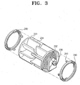
- FIG. 3 is an exploded, perspective view of a driving unit of FIG. 2 ;
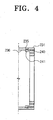
- FIG. 4 is a sectional view of main elements in a state an inertia member of FIG. 3 is mounted in the driving unit;
- FIG. 5 is a perspective view of a second embodiment of a turbine not forming part of the present invention.
- FIG. 6 is a sectional view of the turbine taken on VI-VI line of FIG. 5 ;
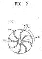
- FIG. 7 is a sectional view of a third embodiment of a turbine not forming part of the present invention.
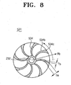
- FIG. 8 is a sectional view of a fourth embodiment of a turbine not forming part of the present invention.
- FIG. 1 is a perspective view of a vacuum cleaner employing a turbine brush according to the first embodiment of the present invention.
- the vacuum cleaner 1 comprises a cleaner body 10 including a vacuum generator (not shown) and a dust collecting chamber (not shown), a turbine brush 200 for drawing in dust from a surface being cleaned, and a connection member 30 for connecting the cleaner body 10 and the turbine brush 200.
- the connection member 30 comprises an operation switch 31 for turning on and off the vacuum cleaner 1.
- the vacuum generator (not shown) generates a suction force for drawing in the dust separated from the surface being cleaned.
- General driving motors can be applied for the vacuum generator.
- the dust collecting chamber (not shown) collects therein the dust drawn in by the suction force of the vacuum generator.
- the turbine brush 200 comprises a turbine brush body 210, a brush member 220, a driving unit 230 and an inertia member 240.
- the turbine brush body 210 is connected to the cleaner body 10 through the connection member 30 to be transmitted with the suction force from the vacuum generator.
- the turbine brush body 210 comprises upper and lower frames 211 and 212, a suction path 213, a brush member receiving portion 214, and a driving unit receiving portion 215.
- the upper and the lower frames 211 and 212 are connected to face each other, thereby constituting an exterior of the turbine brush body 210.
- the lower frame 212 has a suction opening (not shown) for drawing in external air from the surface being cleaned.
- the suction path 213 is formed for the dust drawn in from the surface being cleaned to move to the connection member 30.
- the suction path 213 provides fluid connection between the brush member receiving portion 214 and the driving unit receiving portion 215, such that the drawn-in dust is guided into the dust collecting chamber of the cleaner body 10 sequentially passing through the brush member 220, the driving unit 230 and the connection member 30.
- the brush member receiving portion 214 is fluidly connected to the suction opening that draws in the external air by the suction force.
- the driving unit receiving portion 215 is fluidly connected to the connection member 30, such that the dust drawn in through the suction opening and moved along the brush member 220 and the suction path 213 is guided to the connection member 30.
- the brush member receiving portion 214 and the driving unit receiving portion 215 are sectioned by a partition 216 formed at the lower frame 212.
- the brush member 220 is rotatably mounted to the turbine brush body 210. To this end, the brush member 220 is received in the brush member receiving portion 214 and rotatably supported by the turbine brush body 210 with both ends thereof. A plurality of bristles 221 are implanted at certain intervals along an outer circumference of the brush member 220, and the bristles 221 are exposed to the outside through the suction opening.
- the bristles 221 scratch or beat the dust on the surface being cleaned, thereby separating the dust from the surface being cleaned.
- the separated dust is drawn in through by the suction force generated in the cleaner body 10 and guided into the dust collecting chamber.
- the bristles 221 of this embodiment are illustrated in a spiral form symmetrically implanted with respect to a center portion of the outer circumference of the brush member 220, the present invention is not limited so.
- the bristles 221 may be formed parallel with an axial direction of the brush member 220 at certain intervals. That is, the bristles 221 can be formed in any various types capable of separating the dust from the surface being cleaned.
- the driving unit 230 is rotatably mounted to the driving unit receiving portion 215 which is provided on the suction path 213 in the turbine brush body 210, so as to drive the brush member 220.
- the driving unit 230 comprises a turbine 231, a turbine shaft 232 and a power transmitter 233.
- the turbine 231 is rotated by the air which is drawn in through the suction path 213 by the suction force generated from the vacuum generator.
- the turbine 231 comprises a plurality of blades 234 inwardly protruded from opposite ends of the turbine 231. More preferably, the blades 234 formed from the opposite ends are alternately disposed, such that the turbine 231 1 can be rapidly rotated by the air drawn in along the suction path 213.
- the turbine shaft 232 is inserted in a rotational center of the turbine 231 and supported by the lower frame 212 with opposite ends thereof, such that the turbine 231 is rotatably supported by the turbine brush body 210.
- the power transmitter 233 conveys a rotative force of the turbine 231 to the brush member 220.
- a timing belt connecting the brush member 220 and the turbine shaft 232 of the turbine 231 is used for the power transmitter 233.
- the inertia member 240 is mounted to the turbine 231 for the driving unit 230 to add inertia to a driving force for operating the brush member 220.
- the inertia member 240 is implemented by a mass which rotates together with the turbine 231 for increasing the inertia by adding mass to the rotative force of the turbine 231.
- the inertia member 240 comprises a hook 241 for engagement with a hook hole 235 formed on an inner circumference 236 of the turbine 231.
- the inertia member 240 is formed as a ring in a corresponding shape to the inner circumference 236 of the turbine 231 and fixed in tight contact with opposite sides of the inner circumference 236 of the turbine 231 by the hook 241.
- the inertia member 240 is fixed to the inner circumference 236 of the turbine 231 by the hook 241; however, the present invention is not limited to this structure.
- the inertia member 240 may be attached by a dedicated fixing means such as adhesive or integrally formed with the turbine 231.
- the turbine 231 of the driving unit 230 is rotated together with the inertia member 240, and the rotative force of the turbine 231 is transmitted to the brush member 220 through the power transmitter 233. Therefore, the brush member 220 is rotated to scratch and beat the dust on the surface being cleaned, thereby separating the dust from the surface being cleaned.
- the dust separated by the brush member 220 is drawn in by the suction force and, as passing through the suction path 213 and the connection member 30, collected in the dust collecting chamber in the cleaner body 10.
- the turbine 231 is rotated with the inertia member 240 so that the inertia can be added to the turbine 231 and increase the rotative force.
- the turbine brush according to the second embodiment not forming part of the present invention comprises the turbine brush body 210 and the brush member 220 and may have, for example, the same structures as shown in FIG. 2 and the driving unit 330 with the same structures as shown in FIGS. 5 and 6 .
- the driving unit 330 comprises a second embodiment of a turbine 331, the turbine shaft 232, and the power transmitter 233 (refer to FIG. 2 ).
- the technical constructions of the turbine shaft 232 and the power transmitter 233 may be, for example, the same as described with reference to FIG. 2 .
- the turbine 331 is rotated by air drawn in through the suction path 213 and having a plurality of blades 334 with thickness-varying portions in a direction of radius Rb.
- arcs of the blades 334 of the turbine 331 are uneven in a spiral direction on opposite surfaces 334b to surfaces 334a encountering resistance of air A drawn in by a suction force.
- the thickness Tm of a distal end 334c of the blade 334 may be greater than the other portion of the blade 334 due to the uneven arc.
- the distal end 334c of the blade 334 indicates the distal end 334c furthest from the turbine shaft 232 in the radius direction Rb.
- the arc of the blade 334 is uneven at the distal end 334c, and therefore, the thickness Tm of the distal end 334c is greater than the thickness Tb of the blade 334.
- the distal end 334c of the blade 334 may be made of the same material as the blade 334 or may be made of material different from the blade 334.
- the turbine brush according to the third embodiment not forming part of the present invention is characterized of a third embodiment of a turbine 431 having a plurality of blades 434 with increasing thickness Tb in the direction further away from the turbine shaft 232.
- the thickness Tb of the blade 434 increases in proportion to the length in the radius direction Rb. Therefore, more weight can be added to the blade 434 and increase the inertia.
- the turbine brush according to the fourth embodiment not forming part of the present invention is characterized of a fourth embodiment of a turbine 531 having a plurality of blades 534 with increasing thickness Tb in a direction of the radius Rb and arcs of the blades 534 being uneven in a spiral direction on opposite surfaces 534b of the blades 534.
- the uneven arcs may preferably be formed at the distal ends 534c of the blades 534.
- blades 334 and 434 according to the second and the third embodiments are applied to the blades 534 according to the present embodiment. Therefore, the blades 534 can effectively increase the rotative force.
- inertia member 240 or blades 334, 434, 534 with varying thickness Tb in the radius direction Rb inertia can be increased and therefore, the effect of these particles on the rotative force of the turbine 331, 431, 531 is minimized.
- the turbine 231, 331, 431 or 531 driving the brush member 220 rotates together with the inertia member 240, and may not forming part of the invention have blades 334, 434 or 534 with a thickness-varying portion in a direction of the radius Rb, such that a torque, that is the rotative force according to the centrifugal force of the turbine 231, 331, 431 or 531, can increase.
Landscapes
- Health & Medical Sciences (AREA)
- Life Sciences & Earth Sciences (AREA)
- Engineering & Computer Science (AREA)
- Physics & Mathematics (AREA)
- Hematology (AREA)
- Molecular Biology (AREA)
- Biomedical Technology (AREA)
- Urology & Nephrology (AREA)
- General Health & Medical Sciences (AREA)
- Chemical & Material Sciences (AREA)
- Immunology (AREA)
- Pathology (AREA)
- Mechanical Engineering (AREA)
- Biotechnology (AREA)
- Medical Informatics (AREA)
- Public Health (AREA)
- Veterinary Medicine (AREA)
- Surgery (AREA)
- Diabetes (AREA)
- Optics & Photonics (AREA)
- Biophysics (AREA)
- Cell Biology (AREA)
- Animal Behavior & Ethology (AREA)
- Microbiology (AREA)
- Emergency Medicine (AREA)
- Heart & Thoracic Surgery (AREA)
- Food Science & Technology (AREA)
- Medicinal Chemistry (AREA)
- Analytical Chemistry (AREA)
- Biochemistry (AREA)
- General Physics & Mathematics (AREA)
- Nozzles For Electric Vacuum Cleaners (AREA)
Claims (6)
- Eine Turbinenbürste (200) für einen Staubsauger (1), aufweisend:einen Turbinenbürstenkörper (210), der angepasst ist, mit einem Staubsaugerkörper (10), in dem eine Saugkraft erzeugt wird, verbunden zu sein, und der einen Ansaugpfad (213) darin aufweist,ein Bürstenelement (220), das drehbar an dem Turbinenbürstenkörper montiert ist,eine Antriebseinheit (230, 330), die drehbar in dem Turbinenbürstenkörper montiert ist, um das Bürstenelement anzutreiben, und die aufweist: eine Turbine (231, 331, 431, 531), die durch Luft rotiert wird, die durch den Ansaugpfad (213) hindurch angesaugt wird, und die eine Mehrzahl von Schaufeln (234, 334, 434, 534) aufweist, eine Turbinenwelle (232), die in einem Rotationszentrum der Turbine angeordnet ist, und eine Energieübertragungseinrichtung (233) zum Übertragen einer Rotationskraft der Turbine auf das Bürstenelement (220),dadurch gekennzeichnet, dass sie aufweist:zwei Trägheitselemente (240), die lösbar an der Turbine (231, 331, 431, 531) montiert sind und zusammen mit der Turbine rotiert werden, um einer Antriebskraft der Antriebseinheit Trägheit hinzuzufügen,wobei die beiden Trägheitselemente (240) einen Haken (241) für einen Eingriff mit einem an entgegengesetzten Enden der Turbine (231, 331, 431, 531) ausgebildeten Hakenloch (235) aufweisen, eine ringförmige Form haben und in engem Kontakt mit gegenüberliegenden Seiten des Innenumfangs der Turbine (231, 331, 431, 531) befestigt sind.
- Die Turbinenbürste gemäß Anspruch 1, wobei mindestens eine Schaufel (334, 434, 534) der Mehrzahl von Schaufeln an einem distalen Ende (334c, 534c) davon eine größere Dicke als an einem benachbarten Ende davon hat.
- Die Turbinenbürste gemäß Anspruch 1, wobei die Dicke (Tb) von mindestens einer Schaufel (434, 534) der Mehrzahl von Schaufeln mit Abstand von dem Rotationszentrum größer wird.
- Die Turbinenbürste gemäß Anspruch 3, wobei die Schaufel (534) einen ungleichmäßigen Bogen an einem distalen Ende (534c) an einer entgegengesetzten Fläche (534b) einer Fläche hat, die auf einen Widerstand der Ansaugluft trifft.
- Die Turbinenbürste gemäß Anspruch 1, wobei die Energieübertragungseinrichtung (233) einen Antriebsriemen aufweist, der die Turbinenwelle (232) und das Bürstenelement (220) miteinander verbindet, um Energie zu übertragen.
- Die Turbinenbürste gemäß Anspruch 1, wobei die Antriebseinheit (230, 330) in dem Ansaugpfad (213) in dem Turbinenbürstenkörper (210) angeordnet ist.
Applications Claiming Priority (2)
| Application Number | Priority Date | Filing Date | Title |
|---|---|---|---|
| KR20050019963 | 2005-03-10 | ||
| KR1020050031545A KR100662633B1 (ko) | 2005-03-10 | 2005-04-15 | 진공청소기의 터빈브러쉬 |
Publications (3)
| Publication Number | Publication Date |
|---|---|
| EP1700556A2 EP1700556A2 (de) | 2006-09-13 |
| EP1700556A3 EP1700556A3 (de) | 2008-04-16 |
| EP1700556B1 true EP1700556B1 (de) | 2014-06-04 |
Family
ID=35462629
Family Applications (1)
| Application Number | Title | Priority Date | Filing Date |
|---|---|---|---|
| EP05356161.9A Expired - Lifetime EP1700556B1 (de) | 2005-03-10 | 2005-09-15 | System und Verfahren zur Erhöhung der Trägheit in einer Turbinenbürste |
Country Status (3)
| Country | Link |
|---|---|
| US (1) | US7765639B2 (de) |
| EP (1) | EP1700556B1 (de) |
| KR (1) | KR100662633B1 (de) |
Families Citing this family (11)
| Publication number | Priority date | Publication date | Assignee | Title |
|---|---|---|---|---|
| AU2006201894B2 (en) | 2005-05-05 | 2010-09-16 | Bissell Inc. | Vacuum accessory tool |
| KR100756322B1 (ko) * | 2006-12-06 | 2007-09-06 | 삼성광주전자 주식회사 | 브러쉬장치 및 이를 포함한 진공청소기 |
| CA2684168A1 (en) * | 2009-10-30 | 2011-04-30 | G.B.D. Corp. | Surface cleaning head |
| CA2905794C (en) | 2013-03-11 | 2018-02-27 | Pentair Water Pool And Spa, Inc. | Two-wheel actuator steering system and method for pool cleaner |
| EP2971410A4 (de) | 2013-03-13 | 2017-03-22 | Pentair Water Pool and Spa, Inc. | Alternierender paddelmechanismus für schwimmbeckenreiniger |
| EP2971411A4 (de) | 2013-03-13 | 2017-04-19 | Pentair Water Pool and Spa, Inc. | Doppelpaddelmechanismus für schwimmbeckenreiniger |
| GB201404917D0 (en) * | 2014-03-19 | 2014-04-30 | Dyson Technology Ltd | Cleaner head |
| CN106031607B (zh) * | 2015-03-20 | 2018-09-18 | 天佑电器(苏州)有限公司 | 地刷组件 |
| KR101865315B1 (ko) * | 2016-07-15 | 2018-06-07 | 이원삼 | Ems 레일 크리닝 시스템 |
| CN112401743B (zh) * | 2020-11-18 | 2021-10-15 | 苏州裕谦信息科技有限公司 | 一种家用清洁设备 |
| CN117279554A (zh) * | 2021-09-17 | 2023-12-22 | 三星电子株式会社 | 清洁器的滚筒模块和包括该滚筒模块的清洁器 |
Family Cites Families (17)
| Publication number | Priority date | Publication date | Assignee | Title |
|---|---|---|---|---|
| US2100089A (en) | 1935-05-23 | 1937-11-23 | Hoover Co | Suction cleaner |
| GB489776A (en) | 1937-02-03 | 1938-08-03 | Hoover Co | Improvements in or relating to suction cleaners |
| US2671926A (en) * | 1952-02-12 | 1954-03-16 | Frederick K Minerley | Vacuum operated venetian blind brush |
| AT383264B (de) * | 1980-10-01 | 1987-06-10 | Walkner & Co Ohg Dr H & A | Reinigungsgeraet fuer textilgut, zum anschluss an eine luftabsaugvorrichtung |
| JPH06105772A (ja) | 1992-09-25 | 1994-04-19 | Hitachi Ltd | 電気掃除機の吸口部 |
| JPH06218703A (ja) * | 1993-01-22 | 1994-08-09 | Hitachi Koki Co Ltd | 携帯用電気ルータ |
| EP0780085A1 (de) | 1995-12-21 | 1997-06-25 | Walter Fust | Staubsauger sowie Staubsaugerdüse zum Gebrauch im Staubsauger |
| DE19602406C1 (de) | 1996-01-24 | 1997-01-23 | Wessel Werk Gmbh | Saugkopf, insbesondere Staubsauger-Saugkopf |
| CH692717A5 (de) | 1996-11-20 | 2002-10-15 | Wessel Werk Gmbh | Saugkopf eines Staubsaugers. |
| DE19826041C5 (de) * | 1998-06-12 | 2006-03-30 | Düpro AG | Saugreinigungswerkzeug |
| US6292970B1 (en) | 1999-10-12 | 2001-09-25 | Poolvergnuegen | Turbine-driven automatic swimming pool cleaners |
| KR20000023920A (ko) | 1999-10-12 | 2000-05-06 | 유세형 | 온라인 신용대출 시스템 및 그 방법 |
| DE10042665C5 (de) * | 2000-08-31 | 2010-06-24 | Düpro AG | Saugreinigungswerkzeug mit einer Abströmrampe |
| DE10042672C5 (de) | 2000-08-31 | 2010-05-27 | Düpro AG | Saugreinigungswerkzeug mit Durchströmturbine |
| KR20020071531A (ko) | 2001-03-07 | 2002-09-13 | 대우전자주식회사 | 냉장고용 팬 밸런싱 측정방법 |
| KR100572153B1 (ko) * | 2004-04-02 | 2006-04-24 | 삼성광주전자 주식회사 | 브러시조립체 및 이를 포함한 진공청소기 |
| KR200370526Y1 (ko) | 2004-09-14 | 2004-12-14 | 남도금형(주) | 청소기용 노즐 유니트 |
-
2005
- 2005-04-15 KR KR1020050031545A patent/KR100662633B1/ko not_active Expired - Fee Related
- 2005-08-24 US US11/209,613 patent/US7765639B2/en not_active Expired - Fee Related
- 2005-09-15 EP EP05356161.9A patent/EP1700556B1/de not_active Expired - Lifetime
Also Published As
| Publication number | Publication date |
|---|---|
| KR100662633B1 (ko) | 2007-01-02 |
| KR20060097516A (ko) | 2006-09-14 |
| US20060200935A1 (en) | 2006-09-14 |
| EP1700556A2 (de) | 2006-09-13 |
| EP1700556A3 (de) | 2008-04-16 |
| US7765639B2 (en) | 2010-08-03 |
Similar Documents
| Publication | Publication Date | Title |
|---|---|---|
| EP1604603B1 (de) | Saugkopf für Staubsauger | |
| EP1700556B1 (de) | System und Verfahren zur Erhöhung der Trägheit in einer Turbinenbürste | |
| US9848746B2 (en) | Vacuum cleaner and suction nozzle thereof | |
| EP2085009B1 (de) | Reinigungsgerät | |
| JP2002085301A (ja) | 真空掃除機用パワーブラシアセンブリ | |
| JP3724413B2 (ja) | 電気掃除機用電動送風機及びこれを用いた電気掃除機 | |
| JP2823013B2 (ja) | 電気掃除機及びその吸口体 | |
| JP2003204903A (ja) | 電気掃除機 | |
| EP1604602B1 (de) | Staubsaugersaugkopf | |
| CN217645111U (zh) | 尘杯组件及表面清洁设备 | |
| CN114831534B (zh) | 尘杯组件及吸尘器 | |
| EP1495707B1 (de) | Staubsaugerkopf fuer Staubsauger | |
| JP2001346730A (ja) | 電気掃除機用吸込具並びに電気掃除機 | |
| JPH11253371A (ja) | 電気掃除機およびその吸口体 | |
| JP2005021467A (ja) | 電気掃除機の吸口体及びこれを備えた電気掃除機 | |
| JP4738960B2 (ja) | 電気掃除機用床ノズルと電気掃除機 | |
| KR100199933B1 (ko) | 진공청소기용 브러쉬 | |
| RU2309657C2 (ru) | Щетка турбинного типа для пылесоса | |
| JP2006340827A (ja) | 電気掃除機 | |
| KR20230114510A (ko) | 집진장치 및 이를 갖는 청소기 | |
| EP4388954A1 (de) | Staubsauger | |
| JP2004065355A (ja) | 電動送風機およびこれを搭載した電気掃除機 | |
| JP3536823B2 (ja) | 電気掃除機及びその吸口体 | |
| JP2006296775A (ja) | 電気掃除機の床用吸込具及びそれを備えた電気掃除機 | |
| JP2001198053A (ja) | アップライト型電気掃除機 |
Legal Events
| Date | Code | Title | Description |
|---|---|---|---|
| PUAI | Public reference made under article 153(3) epc to a published international application that has entered the european phase |
Free format text: ORIGINAL CODE: 0009012 |
|
| AK | Designated contracting states |
Kind code of ref document: A2 Designated state(s): AT BE BG CH CY CZ DE DK EE ES FI FR GB GR HU IE IS IT LI LT LU LV MC NL PL PT RO SE SI SK TR |
|
| AX | Request for extension of the european patent |
Extension state: AL BA HR MK YU |
|
| PUAL | Search report despatched |
Free format text: ORIGINAL CODE: 0009013 |
|
| AK | Designated contracting states |
Kind code of ref document: A3 Designated state(s): AT BE BG CH CY CZ DE DK EE ES FI FR GB GR HU IE IS IT LI LT LU LV MC NL PL PT RO SE SI SK TR |
|
| AX | Request for extension of the european patent |
Extension state: AL BA HR MK YU |
|
| 17P | Request for examination filed |
Effective date: 20081016 |
|
| AKX | Designation fees paid |
Designated state(s): GB |
|
| REG | Reference to a national code |
Ref country code: DE Ref legal event code: 8566 |
|
| 17Q | First examination report despatched |
Effective date: 20120105 |
|
| GRAP | Despatch of communication of intention to grant a patent |
Free format text: ORIGINAL CODE: EPIDOSNIGR1 |
|
| INTG | Intention to grant announced |
Effective date: 20140109 |
|
| GRAS | Grant fee paid |
Free format text: ORIGINAL CODE: EPIDOSNIGR3 |
|
| GRAA | (expected) grant |
Free format text: ORIGINAL CODE: 0009210 |
|
| AK | Designated contracting states |
Kind code of ref document: B1 Designated state(s): GB |
|
| REG | Reference to a national code |
Ref country code: GB Ref legal event code: FG4D |
|
| PLBE | No opposition filed within time limit |
Free format text: ORIGINAL CODE: 0009261 |
|
| STAA | Information on the status of an ep patent application or granted ep patent |
Free format text: STATUS: NO OPPOSITION FILED WITHIN TIME LIMIT |
|
| 26N | No opposition filed |
Effective date: 20150305 |
|
| PGFP | Annual fee paid to national office [announced via postgrant information from national office to epo] |
Ref country code: GB Payment date: 20170823 Year of fee payment: 13 |
|
| GBPC | Gb: european patent ceased through non-payment of renewal fee |
Effective date: 20180915 |
|
| PG25 | Lapsed in a contracting state [announced via postgrant information from national office to epo] |
Ref country code: GB Free format text: LAPSE BECAUSE OF NON-PAYMENT OF DUE FEES Effective date: 20180915 |