EP1700559A1 - Paillasson - Google Patents
Paillasson Download PDFInfo
- Publication number
- EP1700559A1 EP1700559A1 EP06075539A EP06075539A EP1700559A1 EP 1700559 A1 EP1700559 A1 EP 1700559A1 EP 06075539 A EP06075539 A EP 06075539A EP 06075539 A EP06075539 A EP 06075539A EP 1700559 A1 EP1700559 A1 EP 1700559A1
- Authority
- EP
- European Patent Office
- Prior art keywords
- profiles
- coupling
- longitudinal
- mat
- profile
- Prior art date
- Legal status (The legal status is an assumption and is not a legal conclusion. Google has not performed a legal analysis and makes no representation as to the accuracy of the status listed.)
- Withdrawn
Links
Images









Classifications
-
- A—HUMAN NECESSITIES
- A47—FURNITURE; DOMESTIC ARTICLES OR APPLIANCES; COFFEE MILLS; SPICE MILLS; SUCTION CLEANERS IN GENERAL
- A47L—DOMESTIC WASHING OR CLEANING; SUCTION CLEANERS IN GENERAL
- A47L23/00—Cleaning footwear
- A47L23/22—Devices or implements resting on the floor for removing mud, dirt, or dust from footwear
- A47L23/26—Mats or gratings combined with brushes ; Mats
-
- Y—GENERAL TAGGING OF NEW TECHNOLOGICAL DEVELOPMENTS; GENERAL TAGGING OF CROSS-SECTIONAL TECHNOLOGIES SPANNING OVER SEVERAL SECTIONS OF THE IPC; TECHNICAL SUBJECTS COVERED BY FORMER USPC CROSS-REFERENCE ART COLLECTIONS [XRACs] AND DIGESTS
- Y10—TECHNICAL SUBJECTS COVERED BY FORMER USPC
- Y10T—TECHNICAL SUBJECTS COVERED BY FORMER US CLASSIFICATION
- Y10T428/00—Stock material or miscellaneous articles
- Y10T428/24—Structurally defined web or sheet [e.g., overall dimension, etc.]
- Y10T428/24033—Structurally defined web or sheet [e.g., overall dimension, etc.] including stitching and discrete fastener[s], coating or bond
- Y10T428/24041—Discontinuous or differential coating, impregnation, or bond
- Y10T428/2405—Coating, impregnation, or bond in stitching zone only
Definitions
- the invention relates to a mat, in particular a door mat, which lies in the course of passing individuals.
- the invention relates in particular to such a mat for use for houses.
- a simple embodiment is the coconut matting.
- Other examples are the synthetic mat, which may or may not have a profile, and the steel grating.
- the invention provides a mat with a tread area for cleaning foot-wear of individuals walking over the mat, comprising a series of longitudinal profiles, formed by extrusion, which are disposed in parallel, which are each provided with an accommodation recess for accommodating a tread area member, such as a brush, furthermore comprising one or more coupling profiles, extending substantially transversely to the longitudinal profiles and comprising first connection means for connection with the longitudinal profiles, wherein two coupling profiles are arranged for respective connection with the longitudinal ends of the longitudinal profiles, and also comprising confining profiles extending along said two coupling profiles, wherein the two coupling profiles and the associated confining profiles are provided with second and third connection means cooperating with each other.
- transverse side of the frame is formed by confining profiles which can be connected with the coupling profiles, without additional securing means, such as screws, bolts, and the like, including adhering.
- the confining profiles When the confining profiles extend over the coupling profiles, the confining profiles also have as a function to hide the rim coupling profiles from view.
- the second and third connection means form a snap connection.
- the second connection means may comprise a convex cam at an upper side of a coupling profile for accommodation in a recess at an inner side of a confining profile.
- the inner side of the coupling profile can be provided with a protrusion which is to be accommodated in a recess at the upper side of the coupling profile so as to realize the snap connection.
- the first connection means for fitting accommodation, in particular clamping accommodation, of the longitudinal profiles.
- the construction height can remain limited.
- the coupling profiles are provided with a base strip, onto which coupling bodies are provided which extend upwards therefrom, and which define adjacent accommodation recesses, wherein the coupling bodies are provided with engagement means for engaging the sides and/or the upper side of the accommodated longitudinal profiles.
- the coupling bodies and longitudinal profiles alternate and they form a continuous series of structural links. Thereby the construction height can also remain limited.
- the coupling bodies can be provided with an upper member, onto which the first connection means are provided, by which a relative upward movement of the longitudinal profiles can be effectively prevented. This is even enhanced when the coupling bodies are provided with an upper part which is provided with confining sections, preferably confining brackets, which engage the upper side of the longitudinal profiles.
- the mat furthermore comprises a run-up profile at at least one longitudinal edge of the mat, preferably at both longitudinal edges.
- the run-up profile or the run-up profiles can form a frame with the coupling profiles and the confining profiles.
- the invention provides a mat with a tread area for cleaning foot-wear of individuals walking over the mat, comprising a series of longitudinal profiles, formed by extrusion, which are disposed in parallel, which are each provided with an accommodation recess for accommodating a tread area member, such as a brush, furthermore comprising one or more coupling profiles, which are substantially transverse to the longitudinal profiles and are each provided with a series of accommodation recesses for accommodating the longitudinal profiles, wherein two coupling profiles are arranged to respectively accommodate the longitudinal ends of the longitudinal profiles, and also comprising confining profiles extending along said two coupling profiles, and also comprising two run-up profiles provided at the longitudinal edges which together with the confining profiles form a frame for the mat.
- the run-up profile is provided with coupling means for coupling with the coupling profiles, in order to facilitate the assembly of the mat.
- the coupling means comprise an accommodation recess for a coupling body of the coupling profiles.
- said accommodation recess is similar to the other accommodation recesses of the coupling profile, so that the coupling profile can be cut to length and yet be coupled at its end with the run-up profile.
- the coupling means comprise a protrusion at the run-up profile which fits in an accommodation recess of the coupling profiles.
- the run-up profile comprises a longitudinal accommodation recess for accommodating a decorative profile, so that the run-up profile can be atuned to taste and use.
- the mat is provided with means for reinforcement of the corner between the run-up profile and the coupling profile.
- the run-up profile may comprise an accommodation recess for a corner reinforcement, such as a steel L-strip.
- the coupling profile and the confining profile can be adapted to clamp between them a part of the corner reinforcement, such as a leg of an L-strip.
- the mat is provided with cover caps for covering the longitudinal ends of the run-up profile.
- corner reinforcement such as an L-strip
- the cover caps can also have a function in confining the above mentioned decorative profile/strip in the run-up profile.
- the longitudinal profiles are provided with antiskid means.
- the longitudinal profiles are provided with an accommodation recess for a skidproof section.
- the longitudinal profiles, the coupling profiles, the tread area members and/or the run-up profiles can be made of material that can be cut to length.
- one or more further coupling profiles can be arranged between the two coupling profiles which are located at the longitudinal ends.
- the invention provides a mat with a tread area for cleaning foot-wear of individuals walking over the mat, comprising a series of longitudinal profiles, formed by extrusion, which are disposed in parallel, which are each provided with an accommodation recess for accommodating a tread area member, such as a brush, furthermore comprising one or more coupling profiles, which are substantially transverse to the longitudinal profiles and each comprise accommodation recesses for accommodating the longitudinal profiles, wherein two coupling profiles are arranged which respectively accommodate the longitudinal ends of the longitudinal profiles.
- the coupling profiles are provided with a base strip, onto which coupling bodies are provided which extend upwards therefrom, defining adjacent accommodation recesses, wherein the coupling bodies are provided with engagement means for engaging the sides and/or the upper side of the accommodated longitudinal profiles.
- German patent application 25 55 125 discloses a mat with longitudinal brush holders which are centrally supported by a strip-shaped holder and which are supported at the ends by strip-shaped end holders, connected therewith by a welding joint.
- the ends of the brushes and the end holders can be covered by means of an upright strip, which can be attached to the end holders by means fo screws or additionally added spring clamps.
- the invention provides a mat with a tread area for cleaning foot-wear of individuals walking over the mat, comprising a series of longitudinal profiles which are disposed in parallel, for accommodating respective tread area members, such as brushes, furthermore comprising one or more coupling profiles, which are substantially transverse to the longitudinal profiles and each comprise first connection means for connection with the longitudinal profiles, wherein two coupling profiles are arranged for respective connection with the longitudinal ends of the longitudinal profiles, and also comprising confining profiles which extend along the two coupling profiles, and which themselves can be attached to the coupling profiles, furthermore comprising at at least one longitudinal edge of the mat a run-up profile, which can be attached to the coupling profile by self-clamping, corner reinforcements for reinforcement of the corners between coupling profiles and run-up profile, wherein the corner reinforcements are locked in-between the confining profiles and the coupling profiles.
- Such a mat can be assembled without the need of common mechanical connection means, such as screws and bolts, or addition of an adhesive or application of (ultrasonic) welding.
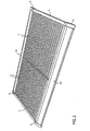
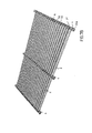
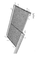
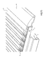
- the exemplary mat 1 comprises a series of base profiles 2, in which tread area members 3 can be accommodated, a number, three in this case, of coupling profiles 4, in which the base profiles 2 are confined, longitudinally extending cover profiles or run-up profiles 5 in which decorative or buffer strips 10 can be accommodated, corner pieces 7, at each corner of the mat 1, confining profiles 6, at both transverse edges of the mat 1, cover caps 8 at each corner of the mat 1 and, at the bottom side of the base profiles 2, skidproof strips 9.
- the base profiles 2, tread area members 3, skidproof profiles 9, run-up profiles 5, decorative strips 10 and confining profiles 6 are made of a material which, at the location where the mat will be used, can be cut to the required length, such as by sawing, cutting and the like.
- the base profiles 2, run-up profiles 5, decorative strips 10 and confining profiles 6 can be formed by means of extrusion of synthetic material or any other suitable material, for instance aluminium.
- the run-up profile 5, illustrated in figures 3A ff. can for instance be formed of aluminium or PVC, and comprises a base strip 11 to be placed on a base, and above said base strip 11 a confining space 12 is formed for the decorative or buffer strip 10 (figure 3B).
- the recess 12 is bounded by a flanged lip 18.
- the accommodation recess 12 is bounded by an upright wall 19, from which a curved wall 14 declines, which slopes down in the vertical leg 14a, which together with a somewhat inwards disposed leg 14b, forms a cavity 15.
- FIG. 14b Between the leg 14b and the wall 19 another accommodation recess 13 is formed for a coupling body 51 of the coupling profile 4 illustrated in figures 5A ff. Furthermore an accommodation recess 17 is formed at the wall 19, bounded by longitudinal ribs 16a and 16b.
- the base strip 11 has an elevated section 11 a, beneath which a cavity 12a is formed. Underneath the legs 14a, 14b a recess 13a has been left.
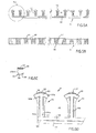
- the base strip 2, illustrated in figure 4A is formed, by extrusion, of aluminium or PVC and comprises a body 20, with side walls 21 a and 21 b.
- the side walls 21 a and 21 b converge upwards to curved upper wall members 22a, 22b, which terminate at a distance from each other so as to leave a slot 23.
- the slot 23 is bounded downwards by sloping walls 30a, 30b, which terminate at a distance above walls 31 a, 31 b which extend towards each other transversely to the walls 21 a, 21 b.
- a transverse wall 24 which comprises a circularly curved wall member 25, which extends upwards and which is provided with a rib 32.
- a transverse wall 24 Above the rib 32, bounded sidewards by the walls 31 a, 31 b and obliquely upwards through the walls 30a, 30b an accommodation recess 23a is realized, which converges upwards to the slot 23.
- an accommodation recess 26 is formed, which is bounded dowards by ribs 27a, 27b, below which an accommodation recess 28 is located.
- the walls 21 a, 21 b are provided with support surfaces 29a, 29b.
- the base profile 2 is provided with/has a skidproof strip 33 and a scraper strip or brush strip 3, as an embodiment of a tread area member.
- the skidproof strip 33 comprises a skidproof lower surface 34 and at the upper side it comprises a fastening rib 35, which comprises a cavity 36 for impression-flexibility.
- snap cams 37a, 37b are provided.
- snap cams 37a, 37b can be moved towards each other as a consequence of the cavity 36, at a force which is excerted by the ribs 27a, 27b.
- the brush strip 3 comprises a strip-shaped base member 40, with a thicker lower end 41 which comprises shoulders 43a, 43b. On top of the base strip 40 brush hairs 42 are provided. After placing the brushes 40 in the direction B in the slot 23 and the accommodation recess 23a the broadened member 41 is confined between the rib 32, the walls 31 a, 31 b, and the walls 30a, 30b, as illustrated in figure 4B. At the ends 3' the brush strip 3 has no brush hairs 42.
- the base strip 2' as illustrated in figure 4C has been embodied more simply, wherein the transverse wall 24' now defines the bottom surface with the corrugated profile 29'. Then a separate skidproof profile is not necessary. Again at the upper side, as in the base profile 2 of figure 4A, an accommodation recess 23', 23a' is formed, as illustrated.
- the coupling profile 4, illustrated in figures 5A-D, can be formed by die casting, of a synthetic material, for instance polypropene.
- the coupling profile 4 comprises a base strip 50, wherein at one longitudinal edge thereof a downwards sloping abutment rib 52 is formed, which forms a recess 59 together with the strip 50.
- coupling bodies 51 are moulded at the upper side of the base strip 50, with an upright body 53 and at the side of the edge 52 upright reinforcement ribs 54a, 54b which are transverse to the bodies 53. Between the coupling bodies 51 accommodation recesses 58 have been left.
- the reinforcement ribs 54a, 54b and the body 53 converge upwards to an upper wall 55, which has a convex upper surface 56 with wall members 55a, 55b which are curved downards to both sides, which define the shape of a T with the body 53.
- the edges of the reinforcing ribs 54a, 54b which are directed towards the accommodation recess 58, and the downwards curved wall members 55a, 55b define a contour of the accommodation recess 58, the shape of which corresponds with the outer contour of the walls 21 a, 21 b, 22a, 22b, 22a', 22b' of the base profiles 2 as illustrated in figures 4A-C.
- a cam 57 is moulded at the upper surface 56 of the wall 55.
- FIGS 6A-C one of the two embodiments of the cover caps 8 is illustrated. It is suitable for two of the corners of the mat 1. For the other corners a similar cover cap 8 will be used, but in a reflected embodiment.
- the cover cap 8 comprises a synthetic body 60, for instance formed by die casting of for instance aluminium, ABS or polypropene.
- the body 60 comprises a vertical wall 61 and a largely curved upper wall 62, with a flat end part 62a and a curved section 62b.
- Support plates 63a, 63b extend from the bottom edge of the upright wall 61, which comprise profiled sections at the upper surface.
- a snap pin 64 extends transversely from the wall 61, and in this example it comprises two snap brackets 64a, 64b.
- angle irons 7 also belong to the assembly of the mat 1, vide also in particular figure 7D. They are L-shaped, with a leg 7a and a leg 7b. A hole 7c is formed in the leg 7b, with which the snap pin 64 can cooperate in a snapping manner.
- the mat 1 furthermore comprises confining profiles 6, further illustrated in figure 7H, at the left.
- the defining profile 6 can be made by extrusion, of synthetic material, for instance polypropene or PVC. It is a substantially U-shaped body 70, with an upper wall 71, a side wall 72, and a bottom wall 73. In the upper wall 71, at the bottom side thereof, a snap slot 75 is formed, which can cooperate with the cams 57 on the coupling profiles 4 for snap-action. In the side wall 72 a slot 74 is left, to accommodate the leg 7b of the angle iron 7.
- the coupling profiles 4 are placed on a ground 100.
- an additional coupling profile 4 can be laid between the two edgecoupling profiles 4.
- the base profiles 2 are shifted in the direction C (which may or may not already have been provided with antiskid profiles 30, in a manner as illustrated in figure 4B) into the accommodation recesses 58 of the coupling profiles 4, wherein the longitudinal ends thereof are accommodated between the upright reinforcement ribs 54a, 54b and the downwards curved wall members 55a, 55b.
- the edges of the curved upper wall members 55a, 55b push against the curved upper wall members 22a, 22b of the base profiles 2, so that at that location the base profiles 2 are clampingly and tightly retained by the coupling profiles 4.
- the wall members 55a, 55b can be somewhat resilient, for a permanent grip, also on the long term.
- the coupling body 51 a which is located at the end of the coupling profile 4, fits clampingly in the accommodation recess 13 of the run-up profile 5.
- the legs 14a and 14b extend between two adjacent coupling bodies 51 a, b (figure 7D) in the accommodation recess 58 which is defined therebetween.
- the angle steels 7 are then inserted at the four corners, with the leg 7a in a friction fit in the slot 17, provided for that purpose, in the run-up profile 5. Then the hole 7c is located in front of the recess 15.
- the buffer strips 10 are placed (direction F) in the accommodation recesses 12 of the run-up profiles 5.
- the confining profiles 6 are placed, as illustrated in figure 7F.
- the confining profiles 6 are shifted in the direction G over and under the coupling profiles 4, wherein the bottom wall 73 fits in the recess 59 and with the edge it abuts against the abutment edge 52 at the coupling profiles 4 and the snap cams 57 snap in the slot 75 at the bottom side of the upper wall 71 of the confining profile 6.
- the bottom side of the wall 73 is aligned with the bottom side of the bottom edge 52.
- cover caps 8 are placed, wherein the snap pins snap in holes 7c, and extend further into the recess 15.
- Support plate 63a then extends into the cavity 12a and the support plate 63b extends into the cavity 13a. Then the upper wall 62 ensures upward confinement of the buffer strip 10 in the accommodation recess 12.
- the upper walls 71 of the confining profiles 6 cover the upper side of the coupling profiles 4, and extend over the ends of the brush strip 3', up to the brush hairs 42.
- the mat 1 has been assembled without using additional securing means, such as screws and bolts, or by using an adhesive. Thereby the mat can be easily assembled in situ, for which at most a saw or the like is needed in order to bring the profiles at the required length.
- the mat 1 is selfconnected, and is reinforced against deformation in its plane.
Landscapes
- Floor Finish (AREA)
Applications Claiming Priority (2)
| Application Number | Priority Date | Filing Date | Title |
|---|---|---|---|
| NL1028489A NL1028489C1 (nl) | 2005-03-08 | 2005-03-08 | Mat. |
| NL1028503 | 2005-03-09 |
Publications (1)
| Publication Number | Publication Date |
|---|---|
| EP1700559A1 true EP1700559A1 (fr) | 2006-09-13 |
Family
ID=36581501
Family Applications (1)
| Application Number | Title | Priority Date | Filing Date |
|---|---|---|---|
| EP06075539A Withdrawn EP1700559A1 (fr) | 2005-03-08 | 2006-03-08 | Paillasson |
Country Status (2)
| Country | Link |
|---|---|
| US (1) | US20060204713A1 (fr) |
| EP (1) | EP1700559A1 (fr) |
Families Citing this family (2)
| Publication number | Priority date | Publication date | Assignee | Title |
|---|---|---|---|---|
| US9944017B2 (en) * | 2016-05-12 | 2018-04-17 | R&L Marketing & Sales, Inc. | Ultrasonically welded mat unit and system thereof |
| USD935970S1 (en) | 2019-06-19 | 2021-11-16 | Edward Mauro | Golf cart floor mat |
Citations (10)
| Publication number | Priority date | Publication date | Assignee | Title |
|---|---|---|---|---|
| US1089972A (en) * | 1912-11-05 | 1914-03-10 | Jakob Schumann | Door-mat. |
| US2805437A (en) | 1950-09-22 | 1957-09-10 | William A Lombardi | Brush mat or the like |
| US3862464A (en) * | 1971-03-16 | 1975-01-28 | Erich Arens | Grating |
| DE2412151A1 (de) * | 1971-03-16 | 1975-09-18 | Erich Arens | Rost oder matte, beispielsweise zur begehbaren abdeckung von rinnen, becken, gruben oder als fussabtreter |
| US4029834A (en) | 1975-12-22 | 1977-06-14 | Construction Specialties, Inc. | Floor mat with hinged rigid elongated rails |
| DE2555125A1 (de) | 1975-12-08 | 1977-06-16 | Otto Renner Fa | Gitterrost mit abstreifwirksamen einlagen |
| USRE32061E (en) | 1984-06-11 | 1986-01-07 | Reese Enterprises, Inc. | Coupling member for floor covering sections |
| DE4407231A1 (de) * | 1994-03-04 | 1995-09-07 | Geggus Ems Gmbh | Mattenartiger Fußabstreifer |
| DE29916651U1 (de) * | 1999-09-22 | 1999-12-30 | Waibel, Walter, Götzis | Profilleiste zur Herstellung eines Rahmens für eine Fußmatte |
| JP2003250711A (ja) * | 2002-03-04 | 2003-09-09 | Matteii Japan:Kk | 簀の子形床マット |
Family Cites Families (13)
| Publication number | Priority date | Publication date | Assignee | Title |
|---|---|---|---|---|
| US86512A (en) * | 1869-02-02 | Improved door-mat | ||
| US3808628A (en) * | 1972-06-15 | 1974-05-07 | Specialties Const | Floor mat |
| DE3317410A1 (de) * | 1983-05-13 | 1984-11-15 | Erich 5900 Siegen Arens | Rost zur bildung von laufmatten oder fussabstreifern |
| GB2195080B (en) * | 1986-09-11 | 1990-01-10 | Kimberly Clark Ltd | Improvements in and relating to a mat holder |
| US4866808A (en) * | 1987-01-16 | 1989-09-19 | Evert Zuiddam | Rollable floor mat |
| US4804570A (en) * | 1987-06-03 | 1989-02-14 | Pawling Corporation | Roll-up matting and method of assembly |
| IT1226345B (it) * | 1988-07-11 | 1991-01-11 | Dell Orto Gianni S | Zerbino ad elementi modulari componibili |
| EP0507415B1 (fr) * | 1991-04-05 | 1995-03-15 | TUFTON GmbH | Paillasson |
| US5157804A (en) * | 1991-07-23 | 1992-10-27 | Construction Specialties, Inc. | Roll-up entrance foot mat |
| US5202092A (en) * | 1991-12-03 | 1993-04-13 | Norcross Corporation | Device for monitoring the PH of water based inks |
| US5486392A (en) * | 1994-07-05 | 1996-01-23 | Reese Enterprises, Inc. | Roll-up floor mat |
| US20020119275A1 (en) * | 2000-02-14 | 2002-08-29 | Williamson Jon L. | Modular mats and edging system therefor |
| US7043792B2 (en) * | 2002-04-19 | 2006-05-16 | R&L Marketing & Sales, Inc. | Floor mat system with flanged cover |
-
2006
- 2006-03-08 EP EP06075539A patent/EP1700559A1/fr not_active Withdrawn
- 2006-03-08 US US11/369,951 patent/US20060204713A1/en not_active Abandoned
Patent Citations (10)
| Publication number | Priority date | Publication date | Assignee | Title |
|---|---|---|---|---|
| US1089972A (en) * | 1912-11-05 | 1914-03-10 | Jakob Schumann | Door-mat. |
| US2805437A (en) | 1950-09-22 | 1957-09-10 | William A Lombardi | Brush mat or the like |
| US3862464A (en) * | 1971-03-16 | 1975-01-28 | Erich Arens | Grating |
| DE2412151A1 (de) * | 1971-03-16 | 1975-09-18 | Erich Arens | Rost oder matte, beispielsweise zur begehbaren abdeckung von rinnen, becken, gruben oder als fussabtreter |
| DE2555125A1 (de) | 1975-12-08 | 1977-06-16 | Otto Renner Fa | Gitterrost mit abstreifwirksamen einlagen |
| US4029834A (en) | 1975-12-22 | 1977-06-14 | Construction Specialties, Inc. | Floor mat with hinged rigid elongated rails |
| USRE32061E (en) | 1984-06-11 | 1986-01-07 | Reese Enterprises, Inc. | Coupling member for floor covering sections |
| DE4407231A1 (de) * | 1994-03-04 | 1995-09-07 | Geggus Ems Gmbh | Mattenartiger Fußabstreifer |
| DE29916651U1 (de) * | 1999-09-22 | 1999-12-30 | Waibel, Walter, Götzis | Profilleiste zur Herstellung eines Rahmens für eine Fußmatte |
| JP2003250711A (ja) * | 2002-03-04 | 2003-09-09 | Matteii Japan:Kk | 簀の子形床マット |
Non-Patent Citations (1)
| Title |
|---|
| PATENT ABSTRACTS OF JAPAN vol. 2003, no. 12 5 December 2003 (2003-12-05) * |
Also Published As
| Publication number | Publication date |
|---|---|
| US20060204713A1 (en) | 2006-09-14 |
Similar Documents
| Publication | Publication Date | Title |
|---|---|---|
| KR100382595B1 (ko) | 풋그릴 | |
| US7066685B2 (en) | Drainage grate | |
| US20060080909A1 (en) | Flooring systems | |
| EP1949834B1 (fr) | Paillasson modulaire | |
| CA2203315C (fr) | Grille gratte-pieds | |
| EP1700559A1 (fr) | Paillasson | |
| EP1884182B1 (fr) | Système modulaire de planchers | |
| CN203531335U (zh) | 具有快速组合效能的地垫及其封边组件 | |
| US20040208689A1 (en) | Set of plates, a plate, a coupling structure and locking means therefor | |
| NL1031327C2 (nl) | Mat. | |
| EP3939487B1 (fr) | Paillasson modulaire | |
| CN222479161U (zh) | 型材系统和用于该型材系统的上型材及下型材 | |
| NL1028489C1 (nl) | Mat. | |
| EP1106124B1 (fr) | Dispositif anti-courant d'air pour la fixation de paillassons | |
| CN103443376B (zh) | 栅栏装饰物 | |
| US20050015899A1 (en) | Walk ramp | |
| HK1123171A (en) | Modular mat | |
| JP4785602B2 (ja) | ピット蓋 | |
| JP3011425U (ja) | 格子体組立セット | |
| JPH10195966A (ja) | ピット蓋 | |
| JPH0413350Y2 (fr) | ||
| EP1435427A1 (fr) | Dispositif de finition pour la prévention des accidents | |
| AU8922801A (en) | A joint | |
| FI108845B (fi) | Matto | |
| JP2503601Y2 (ja) | 板状建材の施工構造 |
Legal Events
| Date | Code | Title | Description |
|---|---|---|---|
| PUAI | Public reference made under article 153(3) epc to a published international application that has entered the european phase |
Free format text: ORIGINAL CODE: 0009012 |
|
| AK | Designated contracting states |
Kind code of ref document: A1 Designated state(s): AT BE BG CH CY CZ DE DK EE ES FI FR GB GR HU IE IS IT LI LT LU LV MC NL PL PT RO SE SI SK TR |
|
| AX | Request for extension of the european patent |
Extension state: AL BA HR MK YU |
|
| 17P | Request for examination filed |
Effective date: 20070313 |
|
| AKX | Designation fees paid |
Designated state(s): AT BE BG CH CY CZ DE DK EE ES FI FR GB GR HU IE IS IT LI LT LU LV MC NL PL PT RO SE SI SK TR |
|
| 17Q | First examination report despatched |
Effective date: 20070604 |
|
| STAA | Information on the status of an ep patent application or granted ep patent |
Free format text: STATUS: THE APPLICATION IS DEEMED TO BE WITHDRAWN |
|
| 18D | Application deemed to be withdrawn |
Effective date: 20131001 |