EP1700621A1 - Trainingsfahrrad mit Armtrainingseinrichtung - Google Patents
Trainingsfahrrad mit Armtrainingseinrichtung Download PDFInfo
- Publication number
- EP1700621A1 EP1700621A1 EP05005055A EP05005055A EP1700621A1 EP 1700621 A1 EP1700621 A1 EP 1700621A1 EP 05005055 A EP05005055 A EP 05005055A EP 05005055 A EP05005055 A EP 05005055A EP 1700621 A1 EP1700621 A1 EP 1700621A1
- Authority
- EP
- European Patent Office
- Prior art keywords
- spindle
- wheel
- rotated
- exercising device
- handle stems
- Prior art date
- Legal status (The legal status is an assumption and is not a legal conclusion. Google has not performed a legal analysis and makes no representation as to the accuracy of the status listed.)
- Withdrawn
Links
- 150000001875 compounds Chemical class 0.000 title claims abstract description 34
- 230000008878 coupling Effects 0.000 claims abstract description 39
- 238000010168 coupling process Methods 0.000 claims abstract description 39
- 238000005859 coupling reaction Methods 0.000 claims abstract description 39
- 230000005540 biological transmission Effects 0.000 description 6
- 230000001351 cycling effect Effects 0.000 description 2
- 238000010276 construction Methods 0.000 description 1
- 210000003205 muscle Anatomy 0.000 description 1
- 230000000979 retarding effect Effects 0.000 description 1
Images




Classifications
-
- A—HUMAN NECESSITIES
- A63—SPORTS; GAMES; AMUSEMENTS
- A63B—APPARATUS FOR PHYSICAL TRAINING, GYMNASTICS, SWIMMING, CLIMBING, OR FENCING; BALL GAMES; TRAINING EQUIPMENT
- A63B22/00—Exercising apparatus specially adapted for conditioning the cardio-vascular system, for training agility or co-ordination of movements
- A63B22/06—Exercising apparatus specially adapted for conditioning the cardio-vascular system, for training agility or co-ordination of movements with support elements performing a rotating cycling movement, i.e. a closed path movement
- A63B22/0605—Exercising apparatus specially adapted for conditioning the cardio-vascular system, for training agility or co-ordination of movements with support elements performing a rotating cycling movement, i.e. a closed path movement performing a circular movement, e.g. ergometers
-
- A—HUMAN NECESSITIES
- A63—SPORTS; GAMES; AMUSEMENTS
- A63B—APPARATUS FOR PHYSICAL TRAINING, GYMNASTICS, SWIMMING, CLIMBING, OR FENCING; BALL GAMES; TRAINING EQUIPMENT
- A63B21/00—Exercising apparatus for developing or strengthening the muscles or joints of the body by working against a counterforce, with or without measuring devices
- A63B21/15—Arrangements for force transmissions
- A63B21/157—Ratchet-wheel links; Overrunning clutches; One-way clutches
-
- A—HUMAN NECESSITIES
- A63—SPORTS; GAMES; AMUSEMENTS
- A63B—APPARATUS FOR PHYSICAL TRAINING, GYMNASTICS, SWIMMING, CLIMBING, OR FENCING; BALL GAMES; TRAINING EQUIPMENT
- A63B22/00—Exercising apparatus specially adapted for conditioning the cardio-vascular system, for training agility or co-ordination of movements
- A63B22/0002—Exercising apparatus specially adapted for conditioning the cardio-vascular system, for training agility or co-ordination of movements involving an exercising of arms
- A63B22/001—Exercising apparatus specially adapted for conditioning the cardio-vascular system, for training agility or co-ordination of movements involving an exercising of arms by simultaneously exercising arms and legs, e.g. diagonally in anti-phase
- A63B22/0012—Exercising apparatus specially adapted for conditioning the cardio-vascular system, for training agility or co-ordination of movements involving an exercising of arms by simultaneously exercising arms and legs, e.g. diagonally in anti-phase the exercises for arms and legs being functionally independent
-
- A—HUMAN NECESSITIES
- A63—SPORTS; GAMES; AMUSEMENTS
- A63B—APPARATUS FOR PHYSICAL TRAINING, GYMNASTICS, SWIMMING, CLIMBING, OR FENCING; BALL GAMES; TRAINING EQUIPMENT
- A63B22/00—Exercising apparatus specially adapted for conditioning the cardio-vascular system, for training agility or co-ordination of movements
- A63B22/06—Exercising apparatus specially adapted for conditioning the cardio-vascular system, for training agility or co-ordination of movements with support elements performing a rotating cycling movement, i.e. a closed path movement
- A63B22/0605—Exercising apparatus specially adapted for conditioning the cardio-vascular system, for training agility or co-ordination of movements with support elements performing a rotating cycling movement, i.e. a closed path movement performing a circular movement, e.g. ergometers
- A63B2022/0635—Exercising apparatus specially adapted for conditioning the cardio-vascular system, for training agility or co-ordination of movements with support elements performing a rotating cycling movement, i.e. a closed path movement performing a circular movement, e.g. ergometers specially adapted for a particular use
- A63B2022/0652—Exercising apparatus specially adapted for conditioning the cardio-vascular system, for training agility or co-ordination of movements with support elements performing a rotating cycling movement, i.e. a closed path movement performing a circular movement, e.g. ergometers specially adapted for a particular use for cycling in a recumbent position
Definitions
- the present invention relates to a compound bicycle exercising device, and more particularly to a compound bicycle exercising device having a coupling or transmission device for rotating or driving a spindle by both pushing or moving the handle stems forwardly and pulling the handle stems rearwardly.
- Typical compound bicycle exercising devices comprise a transmission box driven by foot pedals, and a handle pivotally coupled to the transmission box, for allowing the handle to be rotated inwardly and outwardly, and for allowing users to conduct pedal driving or cycling exercises and hand operating exercises simultaneously.
- U.S. Patent No. 4,660,826 to Lee discloses one of the typical compound bicycle exercising devices which also comprises a pair of foot pedals provided to be rotated or driven by the users, and a transmission box driven by the foot pedals to make a rotating bush at its output shaft and to drive a universal joint, in order to drive a saddle supporter and to move the saddle forward and backward.
- a number of connecting rods may couple the universal joint to two handles, to turn the handles inward and outward.
- the handles are directly and simultaneously coupled to the saddle supporter, such that the handles will be moved forward and backward simultaneously while being pulled or driven or actuated by the users, and such that the handles may not be pulled and pushed or operated by the users alternatively to drive the typical compound bicycle exercising devices.
- U.S. Patent No. 5,992,253 to Petersen discloses another typical compound bicycle exercising device which is provided for converting reciprocating motion to a single direction rotational motion, and which comprises two pinions mounted on two one-way clutches respectively, and two racks engaged with the pinions respectively, to drive the shaft when the two racks are moved alternatively.
- the racks are pivotally coupled to two handles or exercise arms respectively, for being moved or operated by the handles or exercise arms.
- the racks should be moved in the driving direction and/or the reciprocal direction at a rate of speed sufficiently fast to overtake the shaft, such that the handles should also be moved or rotated or operated at a rate of speed sufficiently fast to overtake the shaft and may not be suitably operated by the users by their own will.
- the present invention has arisen to mitigate and/or obviate the afore-described disadvantages of the conventional compound bicycle exercising devices.
- the primary objective of the present invention is to provide a compound bicycle exercising device including a coupling or transmission device for rotating or driving a spindle by both pushing or moving the handle stems forwardly and pulling the handle stems rearwardly.
- a compound bicycle exercising device comprising a base, a pair of foot pedals rotatably attached to the base with a spindle and cranks, for being operated by users, a pair of handle stems each having a lower portion pivotally attached to the base with a pivot axle, for being pulled and pushed and operated in reciprocating action by the users, the handle stems each including an upper portion, a first rotary member and a second rotary member secured to the lower portions of the handle stems respectively, and rotated in concert with the handle stems relative to the pivot axle respectively, for allowing the first and the second rotary members to be rotated relative to the pivot axle by the handle stems respectively, a spindle rotatably supported on the base, and including two end portions each having a first follower and a second follower rotatably attached thereon with unidirectional bearings, a first coupling member and a second coupling member coupled to the first and the second rotary members and the first and the second followers respectively, and
- the handle stems each preferably includes a barrel secured to the lower portion thereof, and the first and the second rotary members are secured on the barrel and thus secured to the handle stems and rotated in concert with the handle stems respectively.
- the handle stems each includes a handgrip attached to the upper portion thereof, and arranged to allow the handle stems to be easily operated by the users when pushing forwardly away and rearwardly toward the users.
- the base includes a first wheel rotatably supported thereon, and the spindle includes a second wheel secured thereto and rotated in concert with the spindle and coupled to the first wheel, to allow the first wheel to be rotated by the spindle via the second wheel.
- the base includes a coupling element engaged onto the first wheel and the second wheel, to couple the first wheel and the second wheel together.
- the base includes a brake device attached thereto, and provided to brake the first wheel.
- the base includes a frame disposed thereon, and a seat support on the frame for supporting the users.
- the frame includes a rail provided on top thereof, for slidably and adjustably supporting the seat.
- the frame includes a lever rotatably secured thereto, and a pressing member rotatably attached to the lever and engaged with either of the first and the second coupling members, to straighten and tighten the first and the second coupling members.
- the frame includes a spring member engaged with the lever, to bias the pressing member to engage with and to force against the coupling member.
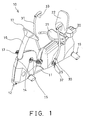
- a compound bicycle exercising device 10 in accordance with the present invention comprises a base 11 including a pair of foot pedals 13 rotatably attached to a front portion 12 of the base 11 with a conventional spindle 14 and cranks 15, for being driven or operated by the users to conduct the conventional cycling exercises, and including a post 16 provided or extended from the front portion 12 of the base 11 and having a control device or a control panel 17 provided on top thereof.
- the compound bicycle exercising device 10 further includes a frame 18 disposed on a rear portion 19 of the base 11 and having a rail 20 formed or provided on top thereof, for and/or optionally slidably and/or adjustably supporting a seat 21 and/or a seat back 22 thereon, and for supporting the users thereon.
- a conventional weight or wheel 23 may further be provided and rotatably supported on the base 11, or rotatably attached to the frame 18, and a brake device 24, such as a typical magnetic retarding or braking device 24 may further be provided to brake the wheel 23 by the users, when required.
- the compound bicycle exercising device 10 further includes a pair of handle stems 30, 31 each having a lower portion 32 rotatably or pivotally attached to the base 11 with a pivot axle 25, for allowing the handle stems 30, 31 to be pulled and pushed or operated in reciprocating operation by the users, and each having a handgrip 33 rotatably or pivotally attached to an upper portion thereof, for allowing the handle stems 30, 31 to be easily and comfortably pulled and pushed or operated by the users.
- the pivotal attachment of the handgrips 33 to top of the handle stems 30, 31 has been filed in a co-pending EP Patent Application, and is not related to the present invention, and thus will not be described in further details.
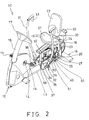
- the handle stems 30 each includes a barrel 34 attached or secured to the lower portion 32 thereof, and two sprockets or gears or pulleys or rotary members 35, 36 secured on the barrel 34 (FIGS. 2, 5) or secured to the handle stems 30 and rotated in concert with the handle stems 30 relative to the pivot axle 25, for allowing the rotary members 35, 36 and the barrel 34 to be rotated relative to the pivot axle 25 by the handle stems 30, 31.
- Two belts or gears or chains or coupling members 37, 38 may be provided and attached or engaged onto the rotary members 35, 36 respectively, for coupling the rotary members 35, 36 to the other parts or elements which will be discussed hereinafter.
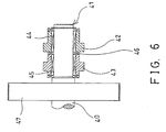
- the compound bicycle exercising device 10 further includes a spindle 40 provided on or attached to or supported on the base 11, such as rotatably attached to the frame 18 of the base 11, and having two end portions 41, and includes two sprockets or gears or pulleys or rotary members or followers 42, 43 rotatably attached onto each of the end portions 41 of the spindle 40 with unidirectional bearings 44, 45 (FIGS. 5 and 6) and coupled to the rotary members 35, 36 with the coupling members 37, 38, for allowing the followers 42, 43 to be rotated relative to the spindle 40 by the handle stems 30, 31, via the followers 42, 43 and the coupling members 37, 38 and the rotary members 35, 36 and the barrel 34.
- a spindle 40 provided on or attached to or supported on the base 11, such as rotatably attached to the frame 18 of the base 11, and having two end portions 41, and includes two sprockets or gears or pulleys or rotary members or followers 42, 43 rotatably attached onto each
- the unidirectional bearings 44, 45 for the followers 42, 43 are provided for allowing the spindle 40 to be continuously rotated and driven by the followers 42, 43 alternatively.
- the spindle 40 is required to be continuously rotated and driven by the followers 42, 43 in an active direction, but the handle stems 30, 31 will be rotated relative to the pivot axle 25 forwardly and rearwardly, or in both the active direction and the reverse direction, and in reciprocating action and alternatively.
- a lever 26 is required to be provided and rotatably secured or attached onto the frame 18 of the base 11, and includes a sprocket or pulley or rotary element 27 rotatably attached to a free end thereof (FIGS.
- the spindle 40 when the rotary member 35 is rotated counterclockwise by the handle stems 30, 31, the spindle 40 may be rotated clockwise, or in the active direction, by the rotary member 35 and the rotary element 27 and the follower 42; and as shown in FIG. 7, the spindle 40 may also be rotated clockwise, or in the active direction, by the other rotary member 36 and the other follower 43 and the other coupling member 38, such that the spindle 40 may be continuously rotated and driven by the followers 42, 43 in the active direction by rotating the handle stems 30, 31 forwardly and rearwardly or alternatively.
- the handle stems 30, 31 may be rotated relative to the pivot axle 25 and may be pulled toward and pushed away from the users and the seat 21 in reciprocating action and alternatively, in order to continuously rotate and drive the spindle 40 in the active direction, and to train the upper muscle groups of the users.
- a thrust bearing 46 is preferably provided and disposed between the unidirectional bearings 44, 45 and the followers 42, 43 (FIG. 6), for suitably separating the followers 42, 43 away from each other, and for preventing the followers 42, 43 from acting or from being contact with each other.
- another follower or weight or wheel 47 may further be provided and secured on the spindle 40, and rotated in concert with the spindle 40, for allowing the wheel 47 to be rotated and driven by the handle stems 30, 31, via the followers 42, 43 and the spindle 40.
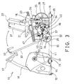
- the wheel 47 may then be coupled to the wheel 23 with a belt or gearing device or chain or coupling element 48 (FIG. 4), for allowing the wheel 23 to be rotated and driven by the wheel 47, and thus for allowing the wheel 23 to provide or to apply a resistive force against the spindle 40 and thus the handle stems 30, 31.
- a lever 50 may further be provided and rotatably secured or attached onto the frame 18 of the base 11, and includes another sprocket or pulley or rotary member or follower or pressing member 51 rotatably attached to a free end thereof (FIGS. 2-4 and 7-8), and engaged with either of the coupling members 37, 38, such as the coupling member 38, and a spring member 52 may be engaged with the lever 50, for biasing the pressing member 51 to engage with or to force against the coupling member 38, in order to straighten or tighten the coupling member 38, and thus to allow the rotary member 36 and the follower 43 to be solidly coupled together with the coupling member 38, and thus to prevent the coupling member 38 from being disengaged from the rotary member 36 and the follower 43.
- one or more levers 54 may further be provided and rotatably secured or attached onto the frame 18 of the base 11, and each includes another sprocket or pulley or rotary member or pressing member 55 rotatably attached to a free end thereof (FIGS. 2-4 and 7-8), and engaged with either of the coupling members 37, 38, such as the other coupling member 37, and may also be biased to engage with or to force against the coupling member 37, in order to straighten or tighten the coupling member 37, and thus to allow the rotary member 35 and the follower 42 to be solidly coupled together with the coupling member 37, and thus to prevent the coupling member 37 from being disengaged from the rotary member 35 and the follower 42.
- the spindle 40 may be continuously rotated and driven in the active direction by both the handle stems 30, 31 that are rotated relative to the pivot axle 25 and pulled toward and pushed away from the users and the seat 21 in reciprocating action and alternatively, via the rotary members 35, 36 and the followers 42, 43 and the coupling members 37, 38.
- the compound bicycle exercising device in accordance with the present invention includes a coupling or transmission device for continuously rotating or driving the spindle and the weight or the wheel in the active direction by rotating the handle stems 30, 31 in reciprocating action and alternatively, by both pushing or moving the handle stems forwardly and pulling the handle stems rearwardly, and thus for allowing the compound bicycle exercising device to be suitably or effectively operated by the users.
Landscapes
- Health & Medical Sciences (AREA)
- General Health & Medical Sciences (AREA)
- Physical Education & Sports Medicine (AREA)
- Cardiology (AREA)
- Vascular Medicine (AREA)
- Life Sciences & Earth Sciences (AREA)
- Biophysics (AREA)
- Orthopedic Medicine & Surgery (AREA)
- Steering Devices For Bicycles And Motorcycles (AREA)
- Transmission Devices (AREA)
Priority Applications (1)
| Application Number | Priority Date | Filing Date | Title |
|---|---|---|---|
| EP05005055A EP1700621A1 (de) | 2005-03-08 | 2005-03-08 | Trainingsfahrrad mit Armtrainingseinrichtung |
Applications Claiming Priority (1)
| Application Number | Priority Date | Filing Date | Title |
|---|---|---|---|
| EP05005055A EP1700621A1 (de) | 2005-03-08 | 2005-03-08 | Trainingsfahrrad mit Armtrainingseinrichtung |
Publications (1)
| Publication Number | Publication Date |
|---|---|
| EP1700621A1 true EP1700621A1 (de) | 2006-09-13 |
Family
ID=34934131
Family Applications (1)
| Application Number | Title | Priority Date | Filing Date |
|---|---|---|---|
| EP05005055A Withdrawn EP1700621A1 (de) | 2005-03-08 | 2005-03-08 | Trainingsfahrrad mit Armtrainingseinrichtung |
Country Status (1)
| Country | Link |
|---|---|
| EP (1) | EP1700621A1 (de) |
Citations (6)
| Publication number | Priority date | Publication date | Assignee | Title |
|---|---|---|---|---|
| US4660826A (en) | 1985-09-16 | 1987-04-28 | Lee Wen Kuei | Folding exercise bike |
| US4871164A (en) * | 1989-04-14 | 1989-10-03 | Tseng D H | Cycle exerciser |
| US5284462A (en) * | 1991-04-03 | 1994-02-08 | Brad Olschansky | Body exercising apparatus |
| US5795270A (en) * | 1996-03-21 | 1998-08-18 | Jim Woods | Semi-recumbent arm and leg press exercising apparatus |
| US5836856A (en) * | 1996-03-22 | 1998-11-17 | Mattoo; Sukhraj Singh | Exercise device |
| US5992253A (en) | 1997-04-08 | 1999-11-30 | Bioform Engineering, Inc. | Method and apparatus for converting reciprocating motion to single direction rotational motion |
-
2005
- 2005-03-08 EP EP05005055A patent/EP1700621A1/de not_active Withdrawn
Patent Citations (6)
| Publication number | Priority date | Publication date | Assignee | Title |
|---|---|---|---|---|
| US4660826A (en) | 1985-09-16 | 1987-04-28 | Lee Wen Kuei | Folding exercise bike |
| US4871164A (en) * | 1989-04-14 | 1989-10-03 | Tseng D H | Cycle exerciser |
| US5284462A (en) * | 1991-04-03 | 1994-02-08 | Brad Olschansky | Body exercising apparatus |
| US5795270A (en) * | 1996-03-21 | 1998-08-18 | Jim Woods | Semi-recumbent arm and leg press exercising apparatus |
| US5836856A (en) * | 1996-03-22 | 1998-11-17 | Mattoo; Sukhraj Singh | Exercise device |
| US5992253A (en) | 1997-04-08 | 1999-11-30 | Bioform Engineering, Inc. | Method and apparatus for converting reciprocating motion to single direction rotational motion |
Similar Documents
| Publication | Publication Date | Title |
|---|---|---|
| US7784808B2 (en) | Rear-pedaling standing type bicycle structure | |
| US4928986A (en) | Arm and leg powered cycle | |
| US8220814B1 (en) | Bicycle propelled by stepping motion | |
| US5145479A (en) | Total body exercising apparatus | |
| US7267639B2 (en) | Compound bicycle exercising device | |
| US5765847A (en) | Pedal mechanism for cycle and exercise equipment | |
| KR20100057684A (ko) | 2개의 왕복 페달을 갖는 인력 차량 | |
| SE467997B (sv) | Motionscykel | |
| US7717448B2 (en) | Ratchet-action drive mechanism for human power | |
| US20030098566A1 (en) | Lever operated foot pump scooter | |
| US7896375B2 (en) | Arm and leg powered bicycle | |
| JP3159237U (ja) | 自転車用駆動構造とそれを利用する自転車 | |
| EP1375333A1 (de) | Fahrzeug mit Energieerzeugungssystem | |
| US20070021277A1 (en) | Upper and lower body exerciser | |
| JP2001519288A (ja) | 直線駆動装置 | |
| US5902216A (en) | Pedal-type exerciser | |
| EP0073470B1 (de) | Fahrrad | |
| EP1815888A1 (de) | Übungsgerät für den Ober- und Unterkörper | |
| CN212880796U (zh) | 具有双重传动机构的踏步运动器材 | |
| US5104137A (en) | Apparatus and method for providing rotary power | |
| FR2805795A3 (fr) | Tricycle d'exercice | |
| CN201424108Y (zh) | 划艇自行车 | |
| DE10158594A1 (de) | Elliptischer Roller | |
| US20030060337A1 (en) | Surfboard simulating exerciser having handle device | |
| JP3111499U (ja) | 複合自転車運動装置 |
Legal Events
| Date | Code | Title | Description |
|---|---|---|---|
| PUAI | Public reference made under article 153(3) epc to a published international application that has entered the european phase |
Free format text: ORIGINAL CODE: 0009012 |
|
| 17P | Request for examination filed |
Effective date: 20050308 |
|
| AK | Designated contracting states |
Kind code of ref document: A1 Designated state(s): AT BE BG CH CY CZ DE DK EE ES FI FR GB GR HU IE IS IT LI LT LU MC NL PL PT RO SE SI SK TR |
|
| AX | Request for extension of the european patent |
Extension state: AL BA HR LV MK YU |
|
| AKX | Designation fees paid |
Designated state(s): AT BE BG CH CY CZ DE DK EE ES FI FR GB GR HU IE IS IT LI LT LU MC NL PL PT RO SE SI SK TR |
|
| STAA | Information on the status of an ep patent application or granted ep patent |
Free format text: STATUS: THE APPLICATION IS DEEMED TO BE WITHDRAWN |
|
| 18D | Application deemed to be withdrawn |
Effective date: 20070314 |