EP1700660A1 - Dispositif de séparation/fraisage - Google Patents
Dispositif de séparation/fraisage Download PDFInfo
- Publication number
- EP1700660A1 EP1700660A1 EP05005246A EP05005246A EP1700660A1 EP 1700660 A1 EP1700660 A1 EP 1700660A1 EP 05005246 A EP05005246 A EP 05005246A EP 05005246 A EP05005246 A EP 05005246A EP 1700660 A1 EP1700660 A1 EP 1700660A1
- Authority
- EP
- European Patent Office
- Prior art keywords
- separating
- milling
- light projection
- projection device
- light
- Prior art date
- Legal status (The legal status is an assumption and is not a legal conclusion. Google has not performed a legal analysis and makes no representation as to the accuracy of the status listed.)
- Granted
Links
Images


Classifications
-
- B—PERFORMING OPERATIONS; TRANSPORTING
- B23—MACHINE TOOLS; METAL-WORKING NOT OTHERWISE PROVIDED FOR
- B23D—PLANING; SLOTTING; SHEARING; BROACHING; SAWING; FILING; SCRAPING; LIKE OPERATIONS FOR WORKING METAL BY REMOVING MATERIAL, NOT OTHERWISE PROVIDED FOR
- B23D59/00—Accessories specially designed for sawing machines or sawing devices
- B23D59/001—Measuring or control devices, e.g. for automatic control of work feed pressure on band saw blade
- B23D59/002—Measuring or control devices, e.g. for automatic control of work feed pressure on band saw blade for the position of the saw blade
- B23D59/003—Indicating the cutting plane on the workpiece, e.g. by projecting a laser beam
-
- B—PERFORMING OPERATIONS; TRANSPORTING
- B23—MACHINE TOOLS; METAL-WORKING NOT OTHERWISE PROVIDED FOR
- B23Q—DETAILS, COMPONENTS, OR ACCESSORIES FOR MACHINE TOOLS, e.g. ARRANGEMENTS FOR COPYING OR CONTROLLING; MACHINE TOOLS IN GENERAL CHARACTERISED BY THE CONSTRUCTION OF PARTICULAR DETAILS OR COMPONENTS; COMBINATIONS OR ASSOCIATIONS OF METAL-WORKING MACHINES, NOT DIRECTED TO A PARTICULAR RESULT
- B23Q1/00—Members which are comprised in the general build-up of a form of machine, particularly relatively large fixed members
- B23Q1/01—Frames, beds, pillars or like members; Arrangement of ways
-
- B—PERFORMING OPERATIONS; TRANSPORTING
- B23—MACHINE TOOLS; METAL-WORKING NOT OTHERWISE PROVIDED FOR
- B23Q—DETAILS, COMPONENTS, OR ACCESSORIES FOR MACHINE TOOLS, e.g. ARRANGEMENTS FOR COPYING OR CONTROLLING; MACHINE TOOLS IN GENERAL CHARACTERISED BY THE CONSTRUCTION OF PARTICULAR DETAILS OR COMPONENTS; COMBINATIONS OR ASSOCIATIONS OF METAL-WORKING MACHINES, NOT DIRECTED TO A PARTICULAR RESULT
- B23Q1/00—Members which are comprised in the general build-up of a form of machine, particularly relatively large fixed members
- B23Q1/25—Movable or adjustable work or tool supports
- B23Q1/44—Movable or adjustable work or tool supports using particular mechanisms
- B23Q1/56—Movable or adjustable work or tool supports using particular mechanisms with sliding pairs only, the sliding pairs being the first two elements of the mechanism
- B23Q1/60—Movable or adjustable work or tool supports using particular mechanisms with sliding pairs only, the sliding pairs being the first two elements of the mechanism two sliding pairs only, the sliding pairs being the first two elements of the mechanism
- B23Q1/62—Movable or adjustable work or tool supports using particular mechanisms with sliding pairs only, the sliding pairs being the first two elements of the mechanism two sliding pairs only, the sliding pairs being the first two elements of the mechanism with perpendicular axes, e.g. cross-slides
- B23Q1/621—Movable or adjustable work or tool supports using particular mechanisms with sliding pairs only, the sliding pairs being the first two elements of the mechanism two sliding pairs only, the sliding pairs being the first two elements of the mechanism with perpendicular axes, e.g. cross-slides a single sliding pair followed perpendicularly by a single sliding pair
- B23Q1/626—Movable or adjustable work or tool supports using particular mechanisms with sliding pairs only, the sliding pairs being the first two elements of the mechanism two sliding pairs only, the sliding pairs being the first two elements of the mechanism with perpendicular axes, e.g. cross-slides a single sliding pair followed perpendicularly by a single sliding pair followed perpendicularly by a single sliding pair
-
- Y—GENERAL TAGGING OF NEW TECHNOLOGICAL DEVELOPMENTS; GENERAL TAGGING OF CROSS-SECTIONAL TECHNOLOGIES SPANNING OVER SEVERAL SECTIONS OF THE IPC; TECHNICAL SUBJECTS COVERED BY FORMER USPC CROSS-REFERENCE ART COLLECTIONS [XRACs] AND DIGESTS
- Y10—TECHNICAL SUBJECTS COVERED BY FORMER USPC
- Y10S—TECHNICAL SUBJECTS COVERED BY FORMER USPC CROSS-REFERENCE ART COLLECTIONS [XRACs] AND DIGESTS
- Y10S362/00—Illumination
- Y10S362/802—Position or condition responsive switch
-
- Y—GENERAL TAGGING OF NEW TECHNOLOGICAL DEVELOPMENTS; GENERAL TAGGING OF CROSS-SECTIONAL TECHNOLOGIES SPANNING OVER SEVERAL SECTIONS OF THE IPC; TECHNICAL SUBJECTS COVERED BY FORMER USPC CROSS-REFERENCE ART COLLECTIONS [XRACs] AND DIGESTS
- Y10—TECHNICAL SUBJECTS COVERED BY FORMER USPC
- Y10T—TECHNICAL SUBJECTS COVERED BY FORMER US CLASSIFICATION
- Y10T83/00—Cutting
- Y10T83/828—With illuminating or viewing means for work
Definitions
- the invention relates to a separating / milling device with the features of the preamble of claim 1 and a separating / milling device having the features of the preamble of claim 4.
- Separating / milling devices are devices that are used for material processing, in particular for cutting and / or milling of the material to be processed. Special fields of application for a cutting / milling device are woodworking, plastics processing and metalworking. However, such a device can also be used in other fields of application. Under a cutting / milling device are especially chop saws, band saws, circular saws, especially table saws, jigsaws, milling and cut-off machines to understand.
- the known, the starting point of the present invention forming miter saw ( DE 10 2004 011 491 A1 ) has a motor-driven saw blade, a workpiece support surface and a light projection device.
- the light projection device projects a light beam onto a workpiece arranged for sawing on the workpiece support surface.
- the light beam is already projected onto the workpiece when the saw blade is still in its rest position, so it has not yet been pivoted into the sawing position.
- the light beam thus marks the cutting position or the cutting profile on the workpiece depending on whether the light beam substantially marks a point or a line on the workpiece.
- the light projection device is arranged in this miter saw on the support of the saw unit or on a portion of a handle.
- Light projection devices of the type in question are also suitable for use in from above on a workpiece to be machined separating / milling devices, so hand circular saws, jigsaws o. The like., Which are known in a variety of embodiments for decades ( DE 90 10 761 U1 ).
- the present invention is based on the problem to optimize a cutting / milling device of the type mentioned in terms of the light projection device.
- the invention solves the above-described problem in a separating / milling device having the features of the preamble of claim 1 by the features of the characterizing part of claim 1 and in a separating / milling device having the features of the preamble of claim 4 by the features of the characterizing Part of claim 4.
- the light projection device has a vibration switch.
- the light projection device can be activated by a mechanical vibration of the separating / milling device.
- a mechanical vibration it may, for example, a machine run, so the start of the motor driven separating / milling element, or a manual operation, such.
- the vibration switch allows insofar a simple and uncomplicated activation of the light projection device, so as to be able to align the workpiece with the light beam for processing.
- the light projection device is assigned its own switch, by means of which the operating states “light projection device on” and “light projection device off” can be switched. In the operating state “light projection device on”, this can be activated by a mechanical vibration, while in the operating state “light projection device off” a mechanical vibration does not lead to an activation of the light projection device.
- the additional switch thus prevents unwanted operation of the Lichtêtionsvotraum by a mechanical vibration, for example, during transport of the separating / milling device.
- the light projection device has a timer which switches it off after a predetermined period of time - the switch-off period. This ensures that the light projection device does not remain in operation for an unnecessarily long time after completion of the workpiece machining. In particular, in the case of a power supply by batteries or accumulators, this prevents unnecessary discharging.
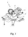
- Fig. 1 shows a separating / milling device 1, which is shown here as a miter saw.
- the separating / milling device 1 has a motor-driven separating / milling element 2, namely a saw blade, a workpiece support surface 3 and a light projection device 4
- the light projecting device 4 projects a light beam onto the workpiece 5 arranged on the workpiece support surface 3.
- the light beam marks the cutting / milling position or the cutting / milling profile on the workpiece 5.
- / Milling position is marked when the light beam substantially marks a point on the workpiece 5, which lies in the working plane of the motor-driven separating / milling 2.
- the cutting / milling process is marked when the light beam marks not only one point in the working plane of the separating / milling element 2 but a line on the workpiece 5.
- the light projection device 4 has a vibration switch 6 (FIG. 4). Due to the vibration switch 6, the light projection device 4 can be activated by a mechanical vibration of the separating / milling device 1.
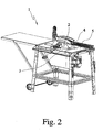
- Fig. 2 shows a separating / milling device 1, which is designed as a table saw.
- a light projection device 4 basically in all cutting / milling devices 1, in which the cutting position or the cutting path before or during the machining of the workpiece 5 without a light projection device 4 is not clearly visible.
- These are, for example, band saws and a combination of a chop saw with a table saw, so a chop and table saw or a miter, miter and table saw.
- FIG. 3 an alternative cutting / milling device 1 is shown, which differs from the separation / milling device 1 described above in that no workpiece support surface 3 is provided with a workpiece 5 thereon, but rather a guide surface 3 ', with the the separating / milling device 1 rests on the workpiece 5.
- the guide surface 3 ' often conceals the cutting / milling position, so that even in this arrangement, the light projection device 4 described above with a vibration switch 6 is advantageously used.
- a separating / milling device 1 can be, for example, a jigsaw, a circular saw, a slot mill or a cut-off machine.
- the light projection device 4 is connected here (FIG. 1) to the power supply of the separating / milling device 1.
- the light projection device 4 can be coupled directly to the power supply of the cutting / milling device 1, d. H. as soon as the separating / milling device 1 is connected to a power supply, the light projection device 4 can also be activated by means of the vibration switch 6.
- the light projection device 4 is coupled to the main switch of the separating / milling device 1. Only an actuation of the main switch of the separation / milling device 1 allows activation of the light projection device 4 by a mechanical vibration. This is particularly advantageous in a separating / milling device 1, in which the motor-driven separating / cutting element 2 is not already activated by actuation of the main switch of the separating / milling device 1, but instead an additional actuation is required, for example pulling a lever on a handle, as is usually the case with a chop saw.
- a separate switch 7 is provided for the light projection device 4 (FIG. 4).
- the Liehtprojeküonsvortechnisch 4 is switched by means of the switch 7 in the operating states "on” and “off".
- the light projection device 4 can be activated by a mechanical vibration, ie in a mechanical vibration of the vibration switch 6 activates the light projection device 4.
- the light projection device 4 is not activated by a mechanical vibration.
- FIG. 4 shows a separating / Fräsvoiraum 1, in which the light projection device 4 has its own power supply 8.
- the own power supply 8 is usually realized by an arrangement of batteries and / or accumulators.
- a separate power supply 8 is particularly advantageous when a connection to the power supply of the separation / milling device 1 is difficult due to the spatial arrangement. This is especially the case with a circular table saw, since the light projection device 4 is advantageously arranged here on the saw blade guard (FIG. 2).
- a separate switch 7 for the light-emitting device 4, as described above, is advantageous (FIG. 4).
- Such a switch 7 makes it possible to switch the light projection device 4 into the operating state "off” and thus to prevent activation of the light projection device 4 by a mechanical vibration, for example during transport of the separating / Fräsvoretztung 1.
- the light projection device 4 has a timer 9 (FIG. 4).
- the Lichtêtionsvomchtung 4 by means of the timer 9 after a predetermined period - Abschalizeitspanne - switched off.
- the light projection device 4 after completion of the processing of the workpiece 5, ie after the last occurrence of a mechanical shock, only continues to operate for a period corresponding to the switch-off period of the timer 9 and then switches off automatically. This prevents the light projection device 4 is activated because a switch-off was forgotten. This is particularly important in a separate power supply 8 of the light projection device 4 of importance.
- a switch-off period is particularly suitable a period of time between one second and ten seconds, especially a period of about five seconds.
- the turn-off period of the timer 9 is adjustable.
- the timer 9 (FIG. 4) shown here is directly coupled to the vibration switch 6. This has the advantage that the light projection device 4 is not turned off during operation of the cutting / milling device 1 after the end of the shutdown period and then turned on again by the vibration switch 6, but is continuously activated and is turned off only after completion of the machining of the workpiece 5 ,
- the light projection device 4 has a positioning laser as the light source 10.
- positioning laser is understood to mean any laser which is suitable for being arranged on a part of the separating / milling device 1 and thereby marking the cutting / milling position or the cutting / milling course on the workpiece 5.
- the light source 10 of the Lichtprpjemiesvortechnisch 4 can be arranged at any point of the separation / milling device 1. However, it is important to ensure that the light source 10 is arranged so that the mark on the workpiece 5 before processing of the workpiece 5 can be seen and preferably during the processing of the workpiece 5. It is also advantageous if the light source 10th is arranged so that the outgoing light beam from the light source 10 is in its entire course in a plane with the cutting / milling element 2. In such an arrangement, the exact marking on the workpiece 5 is independent of the height of the workpiece 5 or a possible pivoting movement of the light projection device 4 and thus a change in height.
- a flanged laser is a laser, which is attached to the flange of the separating / milling 2, ie on the flange of the saw blade.
- the flanging laser is therefore not arranged in a plane with the separating / milling element 2, which results in that the light beam does not impinge perpendicularly but obliquely on the workpiece 5. Consequently, the precise marking on the workpiece 5 height-dependent, so there is a change in height during pivoting of the saw unit with the saw blade and the flange laser and due to this a shift of the mark on the workpiece 5 instead. However, this can be kept within such narrow limits that it is still acceptable for the machining of workpieces 5.
- a cutting / milling device 1 which is a Kapp- and Tischniksäge or a miter, miter and table circular saw
- the light projection device 4 is arranged so that they both in the miter function Cutting position or the cutting path marked on the workpiece 5 as well as in the Tischniksägefunktion.
- a separating / milling device 1 it can also be provided in such a separating / milling device 1 that it has two light projection devices 4 or that a light projection device 4 has two light sources 10. It is particularly advantageous if function-dependent only one of the two light projection devices 4 and the two light sources 10 is activated activated. This can for example be done automatically during the rotation of the saw unit from the capping function in the Tischniksägefunktion or vice versa. It is conceivable that during the rotation of the saw unit corresponding switches are actuated.
Landscapes
- Engineering & Computer Science (AREA)
- Mechanical Engineering (AREA)
- Physics & Mathematics (AREA)
- Optics & Photonics (AREA)
- Sawing (AREA)
- Shovels (AREA)
- Cyclones (AREA)
Priority Applications (5)
| Application Number | Priority Date | Filing Date | Title |
|---|---|---|---|
| DE200550000702 DE502005000702D1 (de) | 2005-03-10 | 2005-03-10 | Trenn-/Fräsvorrichtung |
| ES05005246T ES2285592T3 (es) | 2005-03-10 | 2005-03-10 | Dispositivo de separacion/fresado. |
| AT05005246T ATE361806T1 (de) | 2005-03-10 | 2005-03-10 | Trenn-/fräsvorrichtung |
| EP20050005246 EP1700660B1 (fr) | 2005-03-10 | 2005-03-10 | Dispositif de séparation/fraisage |
| US11/337,483 US7658501B2 (en) | 2005-03-10 | 2006-01-24 | Cutoff/milling device |
Applications Claiming Priority (1)
| Application Number | Priority Date | Filing Date | Title |
|---|---|---|---|
| EP20050005246 EP1700660B1 (fr) | 2005-03-10 | 2005-03-10 | Dispositif de séparation/fraisage |
Publications (2)
| Publication Number | Publication Date |
|---|---|
| EP1700660A1 true EP1700660A1 (fr) | 2006-09-13 |
| EP1700660B1 EP1700660B1 (fr) | 2007-05-09 |
Family
ID=34934177
Family Applications (1)
| Application Number | Title | Priority Date | Filing Date |
|---|---|---|---|
| EP20050005246 Expired - Lifetime EP1700660B1 (fr) | 2005-03-10 | 2005-03-10 | Dispositif de séparation/fraisage |
Country Status (5)
| Country | Link |
|---|---|
| US (1) | US7658501B2 (fr) |
| EP (1) | EP1700660B1 (fr) |
| AT (1) | ATE361806T1 (fr) |
| DE (1) | DE502005000702D1 (fr) |
| ES (1) | ES2285592T3 (fr) |
Cited By (1)
| Publication number | Priority date | Publication date | Assignee | Title |
|---|---|---|---|---|
| EP1946870A1 (fr) | 2007-01-22 | 2008-07-23 | Robert Bosch GmbH | Capteur de proximité pour outils électriques stationnaires |
Families Citing this family (15)
| Publication number | Priority date | Publication date | Assignee | Title |
|---|---|---|---|---|
| USD567975S1 (en) * | 2006-04-12 | 2008-04-29 | Black & Decker Inc. | Light housing for power tool |
| US20080025014A1 (en) * | 2006-07-26 | 2008-01-31 | Hsin-Chin Chen | Adjusting structure of a laser indicator of a sawing machine |
| DE102007032043A1 (de) * | 2007-07-10 | 2009-01-15 | Andreas Stihl Ag & Co. Kg | Arbeitsgerät |
| US8091456B2 (en) | 2008-03-25 | 2012-01-10 | Power Tool Institute | Safety devices for saws |
| US8082826B2 (en) * | 2008-03-25 | 2011-12-27 | Power Tool Institute | Saw accessories and clamp for use therewith |
| US20100147127A1 (en) * | 2008-12-12 | 2010-06-17 | Credo Technology Corporation | Combination table-miter saw with adjustable light |
| JP5444736B2 (ja) * | 2009-01-29 | 2014-03-19 | 日立工機株式会社 | エンジンカッタ、車輪付きエンジンカッタ及び切削方法 |
| US8272303B2 (en) * | 2009-04-28 | 2012-09-25 | Robert Bosch Gmbh | Miter saw with cutting alignment device on a dust chute |
| US20110225831A1 (en) * | 2010-03-17 | 2011-09-22 | Greenwood William T | Rotary Knife For Drywall and the Like |
| US9174319B2 (en) | 2012-08-06 | 2015-11-03 | Michael Dougherty | Illuminated tool rest for lathe |
| US10335915B1 (en) | 2012-08-06 | 2019-07-02 | Michael Dougherty | Kits and methods for installing a light source on a tool rest |
| WO2014093523A1 (fr) * | 2012-12-11 | 2014-06-19 | Robert Bosch Gmbh | Scie circulaire équipée d'un système émetteur de lumière |
| WO2017088639A1 (fr) * | 2015-11-27 | 2017-06-01 | 杜丽娜 | Dispositif de coupe de matériau sur site de construction |
| US11672067B2 (en) | 2021-01-29 | 2023-06-06 | Snap-On Incorporated | Circuit board with sensor controlled lights and end-to-end connection |
| JP7386282B2 (ja) * | 2022-03-14 | 2023-11-24 | 株式会社アマダ | 切断部材処理装置及び切断システム |
Citations (10)
| Publication number | Priority date | Publication date | Assignee | Title |
|---|---|---|---|---|
| DE9010761U1 (de) | 1990-07-19 | 1990-10-04 | Binder Magnete GmbH, 7730 Villingen-Schwenningen | Elektromagnetisch betätigtes Ventil |
| DE29616604U1 (de) | 1996-09-24 | 1996-11-07 | Gottlieb Nestle GmbH & Co KG, 72280 Dornstetten | Markiervorrichtung zur Definition eines Sägeschnittes |
| US6035757A (en) * | 1997-12-15 | 2000-03-14 | Caluori; Raymond | Rotary saw cut alignment device |
| DE20120529U1 (de) * | 2001-12-19 | 2002-03-07 | Z-Laser Optoelektronik GmbH, 79098 Freiburg | Projektionsvorrichtung |
| US20020131267A1 (en) * | 1997-07-10 | 2002-09-19 | Van Osenbruggen Anthony Alfred | Illumination by hand-operated power tools |
| DE20302813U1 (de) * | 2003-02-20 | 2003-04-30 | Taiwan Sheng Tsai Industrial Co., Ltd., Taiping, Taichung | Markiervorrichtung für eine Säge |
| DE10215871C1 (de) * | 2002-04-11 | 2003-10-30 | Laser Optoelektronik Gmbh Z | Projektionsvorrichtung |
| US20030233921A1 (en) * | 2002-06-19 | 2003-12-25 | Garcia Jaime E. | Cutter with optical alignment system |
| US20040083869A1 (en) * | 2002-10-30 | 2004-05-06 | Aziz Edmund J. | Guide |
| DE102004011491A1 (de) | 2003-03-20 | 2004-10-14 | Hitachi Koki Co., Ltd. | Gehrungssäge mit Lichtstrahlprojektionsvorrichtung |
Family Cites Families (4)
| Publication number | Priority date | Publication date | Assignee | Title |
|---|---|---|---|---|
| DE9010716U1 (de) | 1990-07-18 | 1990-09-20 | LAP GmbH Laser Applikationen, 2120 Lüneburg | Richtvorrichtung für Handbearbeitungsmaschinen, insbesondere für Sägen |
| US5461790A (en) * | 1994-02-16 | 1995-10-31 | Olstowski; Franek | Circular saws with laser guides for more precise movement during cutting |
| JP2001025982A (ja) * | 1999-07-13 | 2001-01-30 | Makita Corp | 操作性が向上した照明装置付き電動工具とその使用方法 |
| US7029149B2 (en) * | 2003-11-18 | 2006-04-18 | Hsin Chih Tung | Laser alignment device of a circular saw machine |
-
2005
- 2005-03-10 AT AT05005246T patent/ATE361806T1/de active
- 2005-03-10 EP EP20050005246 patent/EP1700660B1/fr not_active Expired - Lifetime
- 2005-03-10 ES ES05005246T patent/ES2285592T3/es not_active Expired - Lifetime
- 2005-03-10 DE DE200550000702 patent/DE502005000702D1/de not_active Expired - Lifetime
-
2006
- 2006-01-24 US US11/337,483 patent/US7658501B2/en not_active Expired - Fee Related
Patent Citations (10)
| Publication number | Priority date | Publication date | Assignee | Title |
|---|---|---|---|---|
| DE9010761U1 (de) | 1990-07-19 | 1990-10-04 | Binder Magnete GmbH, 7730 Villingen-Schwenningen | Elektromagnetisch betätigtes Ventil |
| DE29616604U1 (de) | 1996-09-24 | 1996-11-07 | Gottlieb Nestle GmbH & Co KG, 72280 Dornstetten | Markiervorrichtung zur Definition eines Sägeschnittes |
| US20020131267A1 (en) * | 1997-07-10 | 2002-09-19 | Van Osenbruggen Anthony Alfred | Illumination by hand-operated power tools |
| US6035757A (en) * | 1997-12-15 | 2000-03-14 | Caluori; Raymond | Rotary saw cut alignment device |
| DE20120529U1 (de) * | 2001-12-19 | 2002-03-07 | Z-Laser Optoelektronik GmbH, 79098 Freiburg | Projektionsvorrichtung |
| DE10215871C1 (de) * | 2002-04-11 | 2003-10-30 | Laser Optoelektronik Gmbh Z | Projektionsvorrichtung |
| US20030233921A1 (en) * | 2002-06-19 | 2003-12-25 | Garcia Jaime E. | Cutter with optical alignment system |
| US20040083869A1 (en) * | 2002-10-30 | 2004-05-06 | Aziz Edmund J. | Guide |
| DE20302813U1 (de) * | 2003-02-20 | 2003-04-30 | Taiwan Sheng Tsai Industrial Co., Ltd., Taiping, Taichung | Markiervorrichtung für eine Säge |
| DE102004011491A1 (de) | 2003-03-20 | 2004-10-14 | Hitachi Koki Co., Ltd. | Gehrungssäge mit Lichtstrahlprojektionsvorrichtung |
Cited By (2)
| Publication number | Priority date | Publication date | Assignee | Title |
|---|---|---|---|---|
| EP1946870A1 (fr) | 2007-01-22 | 2008-07-23 | Robert Bosch GmbH | Capteur de proximité pour outils électriques stationnaires |
| EP1946870B1 (fr) * | 2007-01-22 | 2010-09-08 | Robert Bosch GmbH | Capteur de proximité pour outils électriques stationnaires |
Also Published As
| Publication number | Publication date |
|---|---|
| US20060203469A1 (en) | 2006-09-14 |
| DE502005000702D1 (de) | 2007-06-21 |
| ATE361806T1 (de) | 2007-06-15 |
| ES2285592T3 (es) | 2007-11-16 |
| EP1700660B1 (fr) | 2007-05-09 |
| US7658501B2 (en) | 2010-02-09 |
Similar Documents
| Publication | Publication Date | Title |
|---|---|---|
| EP1700660B1 (fr) | Dispositif de séparation/fraisage | |
| DE10251578B3 (de) | Führungsschiene für Handwerkzeugmaschinen mit zugeordnetem Anschlagstück | |
| DE3005860A1 (de) | Handwerkzeugmaschine, insbesondere blechnager | |
| EP2974824B1 (fr) | Système de guidage doté d'une machine-outil portative et rails de guidage | |
| DE10261904A1 (de) | Kreissäge mit Laserausrichtung | |
| DE10261903A1 (de) | Stichsäge mit Laserstrahlausrichtung | |
| DE102011017691A1 (de) | Laserausrichtungssystem für eine Säge | |
| DE2421954C2 (de) | Winkelführung für stationär angeordnete oder mobile Hand-Oberfräsen | |
| US20080127794A1 (en) | HoleClamp | |
| EP0324444A2 (fr) | Dispositif de rainurage | |
| DE69525363T2 (de) | Handbetätigtes motorwerkzeug | |
| EP2082832A2 (fr) | Butée coudée pour une machine-outil manuelle électrique à guidage forcé et machine-outil manuelle électrique dotée d'une butée coudée | |
| DE102005025934C5 (de) | Elektrische Stichsäge | |
| DE1149160B (de) | Motorangetriebenes Handwerkzeug | |
| EP4311617A1 (fr) | Machine d'usinage guidée à la main | |
| DE4417376C1 (de) | Führungsvorrichtung für Fräsmaschinen | |
| DE10300793A1 (de) | Elektrohandwerkzeugmaschine | |
| DE102005034446A1 (de) | Handwerkzeugmaschine, insbesondere Mauerschlitzer, Nutfräse oder Trennschleifer | |
| DE3021322C2 (de) | Werkstückbezogene Vorschubwegbegrenzung eines fahrbaren Sägeaggregates einer Plattensäge | |
| EP4306280A1 (fr) | Organe de travail | |
| DE19856278A1 (de) | Hobelmesser für Hobelmaschinen, insbesondere Handhobelmaschinen für die Holzbearbeitung | |
| DE102022125930A1 (de) | Werkstück-Anschlag-Anordnung für eine Kreissäge | |
| EP4306278A1 (fr) | Organe de travail | |
| DE102023134936A1 (de) | Schnittlängen-Begrenzungsvorrichtung für tragbare Werkzeugmaschinen | |
| DE4224052C2 (de) | Anschlagwinkel für Handarbeitsmaschine |
Legal Events
| Date | Code | Title | Description |
|---|---|---|---|
| PUAI | Public reference made under article 153(3) epc to a published international application that has entered the european phase |
Free format text: ORIGINAL CODE: 0009012 |
|
| 17P | Request for examination filed |
Effective date: 20051019 |
|
| AK | Designated contracting states |
Kind code of ref document: A1 Designated state(s): AT BE BG CH CY CZ DE DK EE ES FI FR GB GR HU IE IS IT LI LT LU MC NL PL PT RO SE SI SK TR |
|
| AX | Request for extension of the european patent |
Extension state: AL BA HR LV MK YU |
|
| GRAP | Despatch of communication of intention to grant a patent |
Free format text: ORIGINAL CODE: EPIDOSNIGR1 |
|
| GRAS | Grant fee paid |
Free format text: ORIGINAL CODE: EPIDOSNIGR3 |
|
| GRAA | (expected) grant |
Free format text: ORIGINAL CODE: 0009210 |
|
| AK | Designated contracting states |
Kind code of ref document: B1 Designated state(s): AT BE BG CH CY CZ DE DK EE ES FI FR GB GR HU IE IS IT LI LT LU MC NL PL PT RO SE SI SK TR |
|
| PG25 | Lapsed in a contracting state [announced via postgrant information from national office to epo] |
Ref country code: FI Free format text: LAPSE BECAUSE OF FAILURE TO SUBMIT A TRANSLATION OF THE DESCRIPTION OR TO PAY THE FEE WITHIN THE PRESCRIBED TIME-LIMIT Effective date: 20070509 |
|
| REG | Reference to a national code |
Ref country code: GB Ref legal event code: FG4D Free format text: NOT ENGLISH |
|
| AKX | Designation fees paid |
Designated state(s): AT BE BG CH CY CZ DE DK EE ES FI FR GB GR HU IE IS IT LI LT LU MC NL PL PT RO SE SI SK TR |
|
| REG | Reference to a national code |
Ref country code: CH Ref legal event code: NV Representative=s name: KELLER & PARTNER PATENTANWAELTE AG Ref country code: CH Ref legal event code: EP |
|
| REG | Reference to a national code |
Ref country code: IE Ref legal event code: FG4D Free format text: LANGUAGE OF EP DOCUMENT: GERMAN |
|
| REF | Corresponds to: |
Ref document number: 502005000702 Country of ref document: DE Date of ref document: 20070621 Kind code of ref document: P |
|
| GBT | Gb: translation of ep patent filed (gb section 77(6)(a)/1977) |
Effective date: 20070620 |
|
| PG25 | Lapsed in a contracting state [announced via postgrant information from national office to epo] |
Ref country code: SE Free format text: LAPSE BECAUSE OF FAILURE TO SUBMIT A TRANSLATION OF THE DESCRIPTION OR TO PAY THE FEE WITHIN THE PRESCRIBED TIME-LIMIT Effective date: 20070809 |
|
| PG25 | Lapsed in a contracting state [announced via postgrant information from national office to epo] |
Ref country code: IS Free format text: LAPSE BECAUSE OF FAILURE TO SUBMIT A TRANSLATION OF THE DESCRIPTION OR TO PAY THE FEE WITHIN THE PRESCRIBED TIME-LIMIT Effective date: 20070909 |
|
| ET | Fr: translation filed | ||
| NLV1 | Nl: lapsed or annulled due to failure to fulfill the requirements of art. 29p and 29m of the patents act | ||
| REG | Reference to a national code |
Ref country code: ES Ref legal event code: FG2A Ref document number: 2285592 Country of ref document: ES Kind code of ref document: T3 |
|
| PG25 | Lapsed in a contracting state [announced via postgrant information from national office to epo] |
Ref country code: PL Free format text: LAPSE BECAUSE OF FAILURE TO SUBMIT A TRANSLATION OF THE DESCRIPTION OR TO PAY THE FEE WITHIN THE PRESCRIBED TIME-LIMIT Effective date: 20070509 |
|
| REG | Reference to a national code |
Ref country code: IE Ref legal event code: FD4D |
|
| PG25 | Lapsed in a contracting state [announced via postgrant information from national office to epo] |
Ref country code: IE Free format text: LAPSE BECAUSE OF FAILURE TO SUBMIT A TRANSLATION OF THE DESCRIPTION OR TO PAY THE FEE WITHIN THE PRESCRIBED TIME-LIMIT Effective date: 20070509 Ref country code: CZ Free format text: LAPSE BECAUSE OF FAILURE TO SUBMIT A TRANSLATION OF THE DESCRIPTION OR TO PAY THE FEE WITHIN THE PRESCRIBED TIME-LIMIT Effective date: 20070509 Ref country code: PT Free format text: LAPSE BECAUSE OF FAILURE TO SUBMIT A TRANSLATION OF THE DESCRIPTION OR TO PAY THE FEE WITHIN THE PRESCRIBED TIME-LIMIT Effective date: 20071009 Ref country code: BG Free format text: LAPSE BECAUSE OF FAILURE TO SUBMIT A TRANSLATION OF THE DESCRIPTION OR TO PAY THE FEE WITHIN THE PRESCRIBED TIME-LIMIT Effective date: 20070809 Ref country code: SI Free format text: LAPSE BECAUSE OF FAILURE TO SUBMIT A TRANSLATION OF THE DESCRIPTION OR TO PAY THE FEE WITHIN THE PRESCRIBED TIME-LIMIT Effective date: 20070509 Ref country code: NL Free format text: LAPSE BECAUSE OF FAILURE TO SUBMIT A TRANSLATION OF THE DESCRIPTION OR TO PAY THE FEE WITHIN THE PRESCRIBED TIME-LIMIT Effective date: 20070509 Ref country code: DK Free format text: LAPSE BECAUSE OF FAILURE TO SUBMIT A TRANSLATION OF THE DESCRIPTION OR TO PAY THE FEE WITHIN THE PRESCRIBED TIME-LIMIT Effective date: 20070509 |
|
| PG25 | Lapsed in a contracting state [announced via postgrant information from national office to epo] |
Ref country code: LT Free format text: LAPSE BECAUSE OF FAILURE TO SUBMIT A TRANSLATION OF THE DESCRIPTION OR TO PAY THE FEE WITHIN THE PRESCRIBED TIME-LIMIT Effective date: 20070509 Ref country code: SK Free format text: LAPSE BECAUSE OF FAILURE TO SUBMIT A TRANSLATION OF THE DESCRIPTION OR TO PAY THE FEE WITHIN THE PRESCRIBED TIME-LIMIT Effective date: 20070509 |
|
| PLBE | No opposition filed within time limit |
Free format text: ORIGINAL CODE: 0009261 |
|
| STAA | Information on the status of an ep patent application or granted ep patent |
Free format text: STATUS: NO OPPOSITION FILED WITHIN TIME LIMIT |
|
| 26N | No opposition filed |
Effective date: 20080212 |
|
| PG25 | Lapsed in a contracting state [announced via postgrant information from national office to epo] |
Ref country code: GR Free format text: LAPSE BECAUSE OF FAILURE TO SUBMIT A TRANSLATION OF THE DESCRIPTION OR TO PAY THE FEE WITHIN THE PRESCRIBED TIME-LIMIT Effective date: 20070810 |
|
| PG25 | Lapsed in a contracting state [announced via postgrant information from national office to epo] |
Ref country code: RO Free format text: LAPSE BECAUSE OF FAILURE TO SUBMIT A TRANSLATION OF THE DESCRIPTION OR TO PAY THE FEE WITHIN THE PRESCRIBED TIME-LIMIT Effective date: 20070509 |
|
| BERE | Be: lapsed |
Owner name: METABOWERKE G.M.B.H. Effective date: 20080331 |
|
| PG25 | Lapsed in a contracting state [announced via postgrant information from national office to epo] |
Ref country code: MC Free format text: LAPSE BECAUSE OF NON-PAYMENT OF DUE FEES Effective date: 20080331 |
|
| PG25 | Lapsed in a contracting state [announced via postgrant information from national office to epo] |
Ref country code: EE Free format text: LAPSE BECAUSE OF FAILURE TO SUBMIT A TRANSLATION OF THE DESCRIPTION OR TO PAY THE FEE WITHIN THE PRESCRIBED TIME-LIMIT Effective date: 20070509 |
|
| PG25 | Lapsed in a contracting state [announced via postgrant information from national office to epo] |
Ref country code: BE Free format text: LAPSE BECAUSE OF NON-PAYMENT OF DUE FEES Effective date: 20080331 |
|
| PG25 | Lapsed in a contracting state [announced via postgrant information from national office to epo] |
Ref country code: CY Free format text: LAPSE BECAUSE OF FAILURE TO SUBMIT A TRANSLATION OF THE DESCRIPTION OR TO PAY THE FEE WITHIN THE PRESCRIBED TIME-LIMIT Effective date: 20070509 |
|
| PG25 | Lapsed in a contracting state [announced via postgrant information from national office to epo] |
Ref country code: LU Free format text: LAPSE BECAUSE OF NON-PAYMENT OF DUE FEES Effective date: 20080310 Ref country code: HU Free format text: LAPSE BECAUSE OF FAILURE TO SUBMIT A TRANSLATION OF THE DESCRIPTION OR TO PAY THE FEE WITHIN THE PRESCRIBED TIME-LIMIT Effective date: 20071110 |
|
| PG25 | Lapsed in a contracting state [announced via postgrant information from national office to epo] |
Ref country code: TR Free format text: LAPSE BECAUSE OF FAILURE TO SUBMIT A TRANSLATION OF THE DESCRIPTION OR TO PAY THE FEE WITHIN THE PRESCRIBED TIME-LIMIT Effective date: 20070509 |
|
| PGFP | Annual fee paid to national office [announced via postgrant information from national office to epo] |
Ref country code: AT Payment date: 20110323 Year of fee payment: 7 Ref country code: CH Payment date: 20110328 Year of fee payment: 7 |
|
| PGFP | Annual fee paid to national office [announced via postgrant information from national office to epo] |
Ref country code: ES Payment date: 20110324 Year of fee payment: 7 |
|
| PGFP | Annual fee paid to national office [announced via postgrant information from national office to epo] |
Ref country code: IT Payment date: 20110330 Year of fee payment: 7 |
|
| REG | Reference to a national code |
Ref country code: CH Ref legal event code: PL |
|
| REG | Reference to a national code |
Ref country code: AT Ref legal event code: MM01 Ref document number: 361806 Country of ref document: AT Kind code of ref document: T Effective date: 20120310 |
|
| PG25 | Lapsed in a contracting state [announced via postgrant information from national office to epo] |
Ref country code: AT Free format text: LAPSE BECAUSE OF NON-PAYMENT OF DUE FEES Effective date: 20120310 Ref country code: LI Free format text: LAPSE BECAUSE OF NON-PAYMENT OF DUE FEES Effective date: 20120331 Ref country code: CH Free format text: LAPSE BECAUSE OF NON-PAYMENT OF DUE FEES Effective date: 20120331 |
|
| PG25 | Lapsed in a contracting state [announced via postgrant information from national office to epo] |
Ref country code: IT Free format text: LAPSE BECAUSE OF NON-PAYMENT OF DUE FEES Effective date: 20120310 |
|
| REG | Reference to a national code |
Ref country code: ES Ref legal event code: FD2A Effective date: 20130710 |
|
| PG25 | Lapsed in a contracting state [announced via postgrant information from national office to epo] |
Ref country code: ES Free format text: LAPSE BECAUSE OF NON-PAYMENT OF DUE FEES Effective date: 20120311 |
|
| REG | Reference to a national code |
Ref country code: FR Ref legal event code: PLFP Year of fee payment: 11 |
|
| PGFP | Annual fee paid to national office [announced via postgrant information from national office to epo] |
Ref country code: DE Payment date: 20150324 Year of fee payment: 11 |
|
| PGFP | Annual fee paid to national office [announced via postgrant information from national office to epo] |
Ref country code: GB Payment date: 20150324 Year of fee payment: 11 Ref country code: FR Payment date: 20150319 Year of fee payment: 11 |
|
| REG | Reference to a national code |
Ref country code: DE Ref legal event code: R119 Ref document number: 502005000702 Country of ref document: DE |
|
| GBPC | Gb: european patent ceased through non-payment of renewal fee |
Effective date: 20160310 |
|
| REG | Reference to a national code |
Ref country code: FR Ref legal event code: ST Effective date: 20161130 |
|
| PG25 | Lapsed in a contracting state [announced via postgrant information from national office to epo] |
Ref country code: DE Free format text: LAPSE BECAUSE OF NON-PAYMENT OF DUE FEES Effective date: 20161001 Ref country code: FR Free format text: LAPSE BECAUSE OF NON-PAYMENT OF DUE FEES Effective date: 20160331 Ref country code: GB Free format text: LAPSE BECAUSE OF NON-PAYMENT OF DUE FEES Effective date: 20160310 |