EP1700736A2 - Neigungsverstellvorrichtung - Google Patents
Neigungsverstellvorrichtung Download PDFInfo
- Publication number
- EP1700736A2 EP1700736A2 EP06003665A EP06003665A EP1700736A2 EP 1700736 A2 EP1700736 A2 EP 1700736A2 EP 06003665 A EP06003665 A EP 06003665A EP 06003665 A EP06003665 A EP 06003665A EP 1700736 A2 EP1700736 A2 EP 1700736A2
- Authority
- EP
- European Patent Office
- Prior art keywords
- worm
- lock
- helical gear
- locking protrusion
- seat back
- Prior art date
- Legal status (The legal status is an assumption and is not a legal conclusion. Google has not performed a legal analysis and makes no representation as to the accuracy of the status listed.)
- Withdrawn
Links
- 238000010276 construction Methods 0.000 description 4
- 230000004048 modification Effects 0.000 description 2
- 238000012986 modification Methods 0.000 description 2
Images

Classifications
-
- B—PERFORMING OPERATIONS; TRANSPORTING
- B60—VEHICLES IN GENERAL
- B60N—SEATS SPECIALLY ADAPTED FOR VEHICLES; VEHICLE PASSENGER ACCOMMODATION NOT OTHERWISE PROVIDED FOR
- B60N2/00—Seats specially adapted for vehicles; Arrangement or mounting of seats in vehicles
- B60N2/02—Seats specially adapted for vehicles; Arrangement or mounting of seats in vehicles the seat or part thereof being movable, e.g. adjustable
- B60N2/22—Seats specially adapted for vehicles; Arrangement or mounting of seats in vehicles the seat or part thereof being movable, e.g. adjustable the back-rest being adjustable
- B60N2/2231—Worm and worm gear articulations
-
- B—PERFORMING OPERATIONS; TRANSPORTING
- B60—VEHICLES IN GENERAL
- B60N—SEATS SPECIALLY ADAPTED FOR VEHICLES; VEHICLE PASSENGER ACCOMMODATION NOT OTHERWISE PROVIDED FOR
- B60N2/00—Seats specially adapted for vehicles; Arrangement or mounting of seats in vehicles
- B60N2/02—Seats specially adapted for vehicles; Arrangement or mounting of seats in vehicles the seat or part thereof being movable, e.g. adjustable
- B60N2/22—Seats specially adapted for vehicles; Arrangement or mounting of seats in vehicles the seat or part thereof being movable, e.g. adjustable the back-rest being adjustable
- B60N2/2227—Seats specially adapted for vehicles; Arrangement or mounting of seats in vehicles the seat or part thereof being movable, e.g. adjustable the back-rest being adjustable and provided with braking systems
Definitions
- the present invention relates to a reclining device attached to, for example, an automobile seat for appropriately adjusting inclination of a seat back with respect to a seat cushion.
- a sector gear is fixed to a seat back while a worm, which can freely engage with and disengage from the sector gear, is rotatably attached to a seat cushion.
- the worm is connected to an operating shaft and, by pulling the operating shaft in the axial direction thereof and by subsequently lifting it up, the engagement between the worm and sector gear is released.
- the seat back tilts and the inclination thereof can be altered quickly.
- the worm and the sector gear reengage with each other to hold the seat back in that position.
- fine adjustment of the inclination of the seat back is required, when the operating shaft is rotated to rotate the worm, the sector gear held in engagement with the worm rotates gradually, making it possible to smoothly alter the seat back to a desired inclination.
- a sector gear and a worm having a lead angle greater than a friction angle are attached to a seat back and a seat cushion, respectively. According to this reclining device, by tilting the seat back, the worm is caused to rotate by way of the sector gear, making it possible to appropriately alter the inclination of the seat back.
- the present invention has been developed to overcome the above-described disadvantages.
- the reclining device includes a worm rotatably mounted on a seat cushion, a helical gear mounted on a seat back and held in engagement with the worm, and a lock cam for locking the worm and the helical gear or releasing the lock of the worm and the helical gear.
- Both the worm and the helical gear have a lead angle greater than a friction angle.
- a lock plate having a locking protrusion formed therewith is interposed between the worm and the lock cam. The lock cam is operable to press the lock plate against the worm to engage the locking protrusion with a portion of the worm, thereby locking the worm and the helical gear.
- This construction eliminates direct contact of the lock cam with the worm and, hence, can improve the feeling of operation and allow smooth operation of the lock cam.
- the worm has a large number of notches formed with a portion thereof, and the locking protrusion of the lock plate engages with one of the notches to lock the worm and the helical gear.
- the lock plate is made of a plate spring, an elastic force of which acts to bias the locking protrusion in a direction in which the engagement of the locking protrusion with the worm is released.
- a reclining device A which includes a pair of brackets 2 (only one is shown in Fig. 1) spaced a predetermined distance so as to confront each other, a worm 4 rotatably mounted between the pair of brackets 2, and a helical gear 6 held in engagement with the worm 4.
- the brackets 2 are mounted on a seat cushion (not shown), while the helical gear 6 is mounted on a seat back (not shown) via a plurality of pins 8, a seat back-mounting bracket 9, and the like.
- the seat back is always biased frontward by an elastic force of a balance spring (not shown). Both the worm 4 and the helical gear 6 held in engagement with each other have a lead angle greater than a friction angle.
- the worm 4 has a front end rotatably supported by a front bearing 10 and a rear end rotatably supported by a rear bearing 12, and both the front and rear bearings 10, 12 are secured to the brackets 2.
- the worm 4 has a large number of equally spaced notches 4a in the form of a gear formed on a tooth crest thereof positioned in proximity to the front bearing 10.
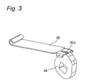
- a lock cam 14 that confronts the notches 4a from below is interposed between the brackets 2 so as to rotate about a mounting shaft 15 secured to the brackets 2.
- a lock plate 16 made of a plate spring is disposed below the worm 4, and one end of the lock plate 16 is connected to a pin 18 secured to the brackets 2, while the other end of the lock plate 16 is interposed between the large number of notches 4a of the worm 4 and the lock cam 14.
- a support pin 20 for supporting the lock plate 16 is secured to the brackets 2 at a location adjacent to the pin 18.
- the lock plate 16 has an elongated locking protrusion 16a formed with the other end thereof so as to protrude towards the notches 4a of the worm 4.
- the lock cam 14 is connected to an operating lever (not shown) that is manually operated to move the locking protrusion 16a of the lock plate 16 up and down to engage or disengage the locking protrusion 16a with or from one of the notches 4a.
- the lock cam 14 is always biased in a direction of an arrow P by an elastic force of a spring (not shown).
- the locking protrusion 16a of the lock plate 16 is pressed against the worm 4 by the lock cam 14 to engage with one of the notches 4a, thereby locking both the worm 4 and the helical gear 6.
- the lock cam 14 is rotated in a direction counter to the direction of the arrow P by operating the operating lever, the locking protrusion 16a is moved away from the notches 4a by an elastic force of the lock plate 16, thereby releasing the engagement between them.
- the reclining device A of the above-described construction operates as follows.
- the lock cam 14 Under the normal condition in which the operating lever connected to the lock cam 14 is not operated, the lock cam 14 is biased in the direction of the arrow P by an elastic force of a biasing means such as a coil spring, and the locking protrusion 16a of the lock plate 16 is held in engagement with one of the notches 4a of the worm 4. Accordingly, rotation of the worm 4 is not allowed, preventing rotation of the helical gear 6 held in engagement with the worm 4. Thus, inclination of the seat back relative to the seat cushion is held at a predetermined angle.
- a biasing means such as a coil spring
- the operating lever When a change in inclination of the seat back is desired, the operating lever is operated to rotate the lock cam 14 in a direction counter to the direction of the arrow P against the elastic force of the biasing means. As a result, the engagement of the locking protrusion 16a with one of the notches 4a of the worm 4 is released by the elastic force of the lock plate 16, and the worm 4 is allowed to rotate freely.
- both the worm 4 and the helical gear 6 held in engagement with each other have a lead angle greater than a friction angle
- the worm 4 can rotate with rotation of the helical gear 6 about its central shaft.
- the seat back is inclined frontward by the elastic force of the balance spring, or inclined rearward by applying a rearward load to the seat back against the elastic force of the balance spring.
- the lock cam 14 is rotated in the direction of the arrow P by the elastic force of the biasing means, and the locking protrusion 16a of the lock plate 16 is again brought into engagement with one of the notches 4a of the worm 4, thereby preventing rotation of the worm 4 to hold the inclination of the seat back at the current angle.
- the reclining device A according to the present invention is effectively utilized in, for example, an automobile seat.
Landscapes
- Engineering & Computer Science (AREA)
- Aviation & Aerospace Engineering (AREA)
- Transportation (AREA)
- Mechanical Engineering (AREA)
- Chairs For Special Purposes, Such As Reclining Chairs (AREA)
- Seats For Vehicles (AREA)
Applications Claiming Priority (1)
| Application Number | Priority Date | Filing Date | Title |
|---|---|---|---|
| JP2005060779A JP2006240534A (ja) | 2005-03-04 | 2005-03-04 | リクライニング装置 |
Publications (2)
| Publication Number | Publication Date |
|---|---|
| EP1700736A2 true EP1700736A2 (de) | 2006-09-13 |
| EP1700736A3 EP1700736A3 (de) | 2010-05-12 |
Family
ID=36699262
Family Applications (1)
| Application Number | Title | Priority Date | Filing Date |
|---|---|---|---|
| EP06003665A Withdrawn EP1700736A3 (de) | 2005-03-04 | 2006-02-23 | Neigungsverstellvorrichtung |
Country Status (2)
| Country | Link |
|---|---|
| EP (1) | EP1700736A3 (de) |
| JP (1) | JP2006240534A (de) |
Cited By (2)
| Publication number | Priority date | Publication date | Assignee | Title |
|---|---|---|---|---|
| CN105857129A (zh) * | 2016-05-27 | 2016-08-17 | 江苏法中航空安全技术有限公司 | 一种可电动调档、摇摆的机动车儿童乘员约束装置 |
| CN112901741A (zh) * | 2021-03-29 | 2021-06-04 | 恺博座椅机械部件有限公司 | 一种可实现手动调节的电动调角器调节机构 |
Citations (2)
| Publication number | Priority date | Publication date | Assignee | Title |
|---|---|---|---|---|
| JPS427950Y1 (de) | 1964-05-11 | 1967-04-20 | ||
| JPH10217817A (ja) | 1997-02-12 | 1998-08-18 | Delta Kogyo Co Ltd | 緊急ロック機構を備えたシートリクライニング装置 |
Family Cites Families (1)
| Publication number | Priority date | Publication date | Assignee | Title |
|---|---|---|---|---|
| US6764136B2 (en) * | 2002-02-26 | 2004-07-20 | Delta Tooling Co., Ltd. | Reclining adjuster |
-
2005
- 2005-03-04 JP JP2005060779A patent/JP2006240534A/ja active Pending
-
2006
- 2006-02-23 EP EP06003665A patent/EP1700736A3/de not_active Withdrawn
Patent Citations (2)
| Publication number | Priority date | Publication date | Assignee | Title |
|---|---|---|---|---|
| JPS427950Y1 (de) | 1964-05-11 | 1967-04-20 | ||
| JPH10217817A (ja) | 1997-02-12 | 1998-08-18 | Delta Kogyo Co Ltd | 緊急ロック機構を備えたシートリクライニング装置 |
Cited By (2)
| Publication number | Priority date | Publication date | Assignee | Title |
|---|---|---|---|---|
| CN105857129A (zh) * | 2016-05-27 | 2016-08-17 | 江苏法中航空安全技术有限公司 | 一种可电动调档、摇摆的机动车儿童乘员约束装置 |
| CN112901741A (zh) * | 2021-03-29 | 2021-06-04 | 恺博座椅机械部件有限公司 | 一种可实现手动调节的电动调角器调节机构 |
Also Published As
| Publication number | Publication date |
|---|---|
| EP1700736A3 (de) | 2010-05-12 |
| JP2006240534A (ja) | 2006-09-14 |
Similar Documents
| Publication | Publication Date | Title |
|---|---|---|
| US7192090B2 (en) | Recliner adjuster | |
| EP1059193B1 (de) | Spielausgleichstruktur für Neigungsverstellvorrichtung | |
| EP1340648B1 (de) | Neigungseinsteller | |
| JP2001097083A (ja) | シートバーチカル装置 | |
| US6976738B2 (en) | Recliner adjuster | |
| JPH0867192A (ja) | 車両用シートのセーフティロック機構 | |
| JP2004512878A (ja) | 自動車シートの水平折り返しリクライニング機構 | |
| US5188423A (en) | Armrest arrangement for a seat | |
| JPH05254447A (ja) | ステアリングコラムアセンブリ | |
| EP1700736A2 (de) | Neigungsverstellvorrichtung | |
| EP1059192A2 (de) | Stufenlose Verstellungsvorrichtung mit Sicherheitsschloss für Kraftfahrzeuge | |
| WO2007043628A1 (ja) | リクライニングアジャスタ | |
| JP3463767B2 (ja) | アームレストの支持構造 | |
| JP7400630B2 (ja) | フロアロック解除機構 | |
| JP3410224B2 (ja) | シートリクライニング装置 | |
| JP2001130292A (ja) | 車両用回転シート | |
| JP3913457B2 (ja) | シート装置 | |
| JP2005287724A (ja) | 車両用シートのアームレスト | |
| JP2582264B2 (ja) | 自動車用シ−トのア−ムレスト取付構造 | |
| JP2589595Y2 (ja) | リクライニング機構 | |
| JP2004314749A (ja) | 電動リクライニングアジャスタ | |
| JP2009050630A (ja) | 車両用シートリクライニング装置 | |
| EP1639919A1 (de) | Vorrichtung zur Einstellung und Stabilisierung der Rückenlehnenneigung eines Stuhles | |
| JPH08300992A (ja) | 車両用シートのセーフティロック機構 | |
| JP2000325172A (ja) | リクライニング機構 |
Legal Events
| Date | Code | Title | Description |
|---|---|---|---|
| PUAI | Public reference made under article 153(3) epc to a published international application that has entered the european phase |
Free format text: ORIGINAL CODE: 0009012 |
|
| AK | Designated contracting states |
Kind code of ref document: A2 Designated state(s): AT BE BG CH CY CZ DE DK EE ES FI FR GB GR HU IE IS IT LI LT LU LV MC NL PL PT RO SE SI SK TR |
|
| AX | Request for extension of the european patent |
Extension state: AL BA HR MK YU |
|
| PUAL | Search report despatched |
Free format text: ORIGINAL CODE: 0009013 |
|
| AK | Designated contracting states |
Kind code of ref document: A3 Designated state(s): AT BE BG CH CY CZ DE DK EE ES FI FR GB GR HU IE IS IT LI LT LU LV MC NL PL PT RO SE SI SK TR |
|
| AX | Request for extension of the european patent |
Extension state: AL BA HR MK YU |
|
| RIC1 | Information provided on ipc code assigned before grant |
Ipc: B60N 2/22 20060101ALI20100408BHEP Ipc: B60N 2/23 20060101AFI20060803BHEP |
|
| AKY | No designation fees paid | ||
| STAA | Information on the status of an ep patent application or granted ep patent |
Free format text: STATUS: THE APPLICATION IS DEEMED TO BE WITHDRAWN |
|
| 18D | Application deemed to be withdrawn |
Effective date: 20101113 |
|
| REG | Reference to a national code |
Ref country code: DE Ref legal event code: R108 Effective date: 20110412 |