EP1700760B1 - Zündschlosssystem für ein Kraftfahrzeug - Google Patents
Zündschlosssystem für ein Kraftfahrzeug Download PDFInfo
- Publication number
- EP1700760B1 EP1700760B1 EP06004343A EP06004343A EP1700760B1 EP 1700760 B1 EP1700760 B1 EP 1700760B1 EP 06004343 A EP06004343 A EP 06004343A EP 06004343 A EP06004343 A EP 06004343A EP 1700760 B1 EP1700760 B1 EP 1700760B1
- Authority
- EP
- European Patent Office
- Prior art keywords
- contour
- detent
- ignition lock
- key
- side wall
- Prior art date
- Legal status (The legal status is an assumption and is not a legal conclusion. Google has not performed a legal analysis and makes no representation as to the accuracy of the status listed.)
- Expired - Lifetime
Links
Images


Classifications
-
- B—PERFORMING OPERATIONS; TRANSPORTING
- B60—VEHICLES IN GENERAL
- B60R—VEHICLES, VEHICLE FITTINGS, OR VEHICLE PARTS, NOT OTHERWISE PROVIDED FOR
- B60R25/00—Fittings or systems for preventing or indicating unauthorised use or theft of vehicles
- B60R25/20—Means to switch the anti-theft system on or off
- B60R25/2063—Ignition switch geometry
-
- B—PERFORMING OPERATIONS; TRANSPORTING
- B60—VEHICLES IN GENERAL
- B60R—VEHICLES, VEHICLE FITTINGS, OR VEHICLE PARTS, NOT OTHERWISE PROVIDED FOR
- B60R25/00—Fittings or systems for preventing or indicating unauthorised use or theft of vehicles
-
- B—PERFORMING OPERATIONS; TRANSPORTING
- B60—VEHICLES IN GENERAL
- B60R—VEHICLES, VEHICLE FITTINGS, OR VEHICLE PARTS, NOT OTHERWISE PROVIDED FOR
- B60R25/00—Fittings or systems for preventing or indicating unauthorised use or theft of vehicles
- B60R25/01—Fittings or systems for preventing or indicating unauthorised use or theft of vehicles operating on vehicle systems or fittings, e.g. on doors, seats or windscreens
- B60R25/04—Fittings or systems for preventing or indicating unauthorised use or theft of vehicles operating on vehicle systems or fittings, e.g. on doors, seats or windscreens operating on the propulsion system, e.g. engine or drive motor
Definitions
- the invention relates to an ignition lock system according to the preamble of patent claim 1.
- an electronic ignition which is actuated by means of an electronic key.
- the electronic ignition key and the electronic key are components of the anti-tamper ignition system.
- an ignition lock system for a motor vehicle which comprises an electronic ignition lock and an electronic key.
- the ignition lock has a receptacle for the key located in a carrier element.
- the carrier element is linearly movable in the manner of a slide by means of the key between a starting position and movement positions, such that the ignition lock can be moved by a simple rectilinear movement of the key, for example by a manual plug-in. and / or pressure movement of the key by the user to operate.
- Two movement positions for the support element are each formed as locking positions, wherein the two locking positions are generated by the interaction of a contour of a double switching heart having locking cam with an engaging in the locking cam, acted upon by an elastic force locking pin.
- an electronic code is interchangeable, so that after positive evaluation of the code at least one effected by the ignition function, such as switching on consumers in the motor vehicle, the starting of the motor vehicle o. The like., Is released in the movement positions and / or is triggered.
- the design of the locking curves as a double switching heart appears to be consuming in a sense.
- the invention has the object of providing the user operable by means of a linear pushing movement, two simple as detent having ignition lock design.
- the other second detent position is generated by the interaction of the detent pin with a detent mechanism, wherein the detent mechanism is acted upon by an elastic force in the direction of the contour of the detent curve.
- the key can be pushed by the simple Druckherzkontur with an additional locking mechanism on the first actuation in the "ignition ON” position and remains in this position. From there, the key can be pulled back into the "OFF position” or, with another actuation, pushed into the "position drive", in which position the slide engages in the switching heart. With repeated actuation in the "position drive” the key arrives in the "position OFF” in the latching position "position ON". Further embodiments of the invention are the subject of the dependent claims.
- the first detent position consist of a depression in the contour of the switching heart. This depression, in which the locking pin is held, is approximately opposite the tip of the switching heart.
- the second detent position is located on a side wall of the contour of the switching heart, and there approximately in the middle between the recess and the top of the switching heart.
- the locking mechanism consists of a clamped leaf spring in the manner of a bending beam.
- the leaf spring acts due to the clamping with a force in the direction of the side wall of the contour of the switching heart.
- the leaf spring is arranged approximately parallel to the side wall of the contour of the switching heart.
- the leaf spring also acts in the manner of a Haptikfeder.
- a part less than otherwise needed for the locking mechanism it is a light Mounting is possible and the feel is easily adjustable via the preload and the angle of the haptic spring. Due to the friction of the steel / steel pair, hardly any abrasion is to be feared.
- this variant is also largely resistant to contamination. However, a small opening in the ignition lock for locking the haptic spring is necessary, so that a Ablrawöffung should be provided for condensation.
- the latching mechanism consists of a one-armed, mounted on a rotary bearing rotary lever.
- the rotary lever can be loaded with a leg spring in the direction of the side wall of the contour of the switching heart.
- the rotary lever with a tip can be approximately perpendicular to the side wall of the contour of the switching heart.
- the haptic on the angle and the leg spring is adjustable.
- the latching mechanism consists of a slide.
- the slide can be loaded with a compression spring in the direction of the side wall of the contour of the switching heart.
- the slider with a tip can be approximately perpendicular to the side wall of the contour of the switching heart.
- the haptic on the angle and the compression spring adjustable.
- two parts are necessary for the locking mechanism here.
- the advantages achieved by the invention are, in particular, that with the aid of the locking mechanism, the feel felt by the operator is adjustable.
- Such an ignition lock consequently increases the ergonomics for the user.
- an ignition lock system 1 for a motor vehicle which consists of an electronic ignition lock 3 and an electronic key 2.
- the built-in, for example, in the dashboard of the motor vehicle ignition 3 has a housing 4.
- the ignition 3 is visible at a visible in Fig. 2 opening 5 in the housing 4 of the key 2 can be inserted.
- the ignition lock 3 has a receptacle 7 for the key 2 located in a carrier element 6.
- the carrier element 6 is by means of the key 2 between a starting position P0 'and one behind the other lying movement positions P0, P1, P2 and P3, which are respectively designated in Fig. 5, manually movable.
- the support member 6 is designed to be linearly movable in the manner of a slider against a stop 25 with compression spring 26, as well as the Fig. 3 can be removed.
- the movement position P1 and the movement position P2 for the support element 6 are each formed as locking positions.
- the first detent position P2 is determined by the interaction of a contour of a switching heart having latching cam 8 (see FIG. 3) with a locking pin 9 (see FIG. 4).
- the locking pin 9 engages in the latching cam 8, as can be seen from FIG. 4.
- the locking pin 9 is arranged on a sliding element 10, which in turn is mounted transversely to the direction of movement of the support member 6 on the carrier element 6, as can be seen from FIGS. 3 and 4.
- the locking pin 9 is acted upon by the sliding element 10 with an elastic force generated by a spring 11.
- the other second detent position P1 is generated by the interaction of the detent pin 9 with a latching mechanism 12, wherein the latching mechanism 12 is acted upon by an elastic force in the direction of the contour of the latching cam 8.
- the key 2 If the key 2 is inserted into the receptacle 7 and this is then brought together with the support member 6 due to manual action of the user on the key 2 from the starting position P0 'in one of the P0 to P3 movement positions, it will be between the key 2 and the ignition 3 an electronic code, preferably in a bidirectional communication, exchanged or transmitted. After positive evaluation of the exchanged between the key 2 and the ignition 3 electronic code, ie it is the legitimate key 2, at least one engageable by the ignition switch 3 function is released and / or triggered. This enabled and / or triggered function can be the switching on of consumers in the motor vehicle, such as the radio, the lighting, etc., the starting of the motor vehicle or the like.
- the electronic code for releasing and / or triggering these functions can, in the movement of the support member 6 between the initial position P0 'and a movement position P0 to P3, in at least one of Movement positions or even if necessary in other positions, for example, already in the starting position P0 ', be exchanged between the key 2 and the ignition switch 3.
- the evaluation of the electronic code can be done in the ignition lock 3 itself or, if desired, in a separate control unit.
- the electronic code can also be transferred from another identification transmitter, such as a separate chip card located at the user, whereby the key 2 then serves merely as a control element in the ignition lock 3 for the user.
- the detailed sequence of operation of the ignition lock system 1 is now as follows.
- the key 2 is inserted into the receptacle 7 and snaps into the receptacle 7 a.
- the so-called “terminal 15" and / or “ignition on” is activated, in which the connection of consumers in the motor vehicle is enabled
- the movement position P1 is a latching movement position for the carrier element 6 together with the key 2.
- the carrier element 6 is moved into the movement position P3 where the motor of the motor vehicle is started P2 then remains in the latching movement position P2 together with the key 2.
- the first detent position P2 consists of a recess 13 in the contour of the switching heart 8.
- the recess 13 is the tip 14 of the switching heart 8 approximately opposite.
- the locking pin 9 is held in the detent position P2 in this recess 13.
- the second detent position P1 is located on a side wall 15th the contour of the switching heart 8, and there in about the middle between the recess 13 and the top 14 of the switching heart. 8
- the closer embodiment of the latching mechanism 12 according to a first embodiment can be seen in Fig. 6.
- the locking mechanism 12 here consists of a clamped leaf spring 16 in the manner of a bending beam.
- the leaf spring 16 now not only acts to produce the detent position P 1 but also acts as a haptic, so as to give the operator a certain haptic feedback upon movement of the key 2 together with the support member 6.
- the leaf spring 16 acts due to the clamping 17 in the housing 4 with a force in the direction of the side wall 15 of the contour of the switching heart 8.
- the leaf spring 16 is arranged approximately parallel to the side wall 15 of the contour of the switching heart 8.
- the latching mechanism 12 according to a further embodiment is shown in Fig. 7.
- the locking mechanism 12 consists of a one-armed, mounted on a pivot bearing 19 rotary lever 18.
- the rotary lever 18 is loaded with a leg spring 20 in the direction of the side wall 15 of the contour of the switching heart 8.
- the rotary lever 18 with a tip 21 is approximately perpendicular to the side wall 15 of the contour of the switching heart. 8
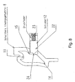
- the latching mechanism 12 according to yet another embodiment in Fig. 8 is shown.
- the latching mechanism 12 consists of a slide 22 which is loaded with a compression spring 23 in the direction of the side wall 15 of the contour of the switching heart 8.
- the slider 22 is connected to a tip 24 approximately perpendicular to the side wall 15 of the contour of the switching heart. 8
- the invention is not limited to the described and illustrated embodiment. Rather, it also encompasses all expert developments within the scope of the invention defined by the claims. Thus, the invention can not only be used on ignition lock systems for any vehicle use, but also on other locks, such as those that are on work machines, real estate o. The like. Be used.
Landscapes
- Engineering & Computer Science (AREA)
- Mechanical Engineering (AREA)
- Lock And Its Accessories (AREA)
Description
- Die Erfindung betrifft ein Zündschloßsystem nach dem Oberbegriff des Patentanspruchs 1.
- In Kraftfahrzeugen befindet sich bei hohen Sicherheitsanforderungen ein elektronisches Zündschloß, das mittels eines elektronischen Schlüssels betätigbar ist. Das elektronische Zündschloß und der elektronische Schlüssel sind Bestandteile des dem Schutz gegen unbefugte Benutzung dienenden Zündschloßsystems.
- Aus der
DE 103 53 195 A1 ist ein Zündschloßsystem für ein Kraftfahrzeug bekannt, das ein elektronisches Zündschloß sowie einen elektronischen Schlüssel umfaßt. Das Zündschloß weist eine in einem Trägerelement befindliche Aufnahme für den Schlüssel auf Das Trägerelement ist in der Art eines Schiebers mittels des Schlüssels zwischen einer Ausgangsstellung und Bewegungsstellungen linear bewegbar, derart daß das Zündschloß durch eine einfache geradlinige Bewegung des Schlüssels, beispielsweise durch eine manuelle Steck- und/oder Druckbewegung des Schlüssels durch den Benutzer, zu bedienen ist. Zwei Bewegungsstellungen für das Trägerelement sind jeweils als Raststellungen ausgebildet, wobei die beiden Raststellungen durch das Zusammenwirken einer die Kontur eines zweifachen Schaltherzens aufweisenden Rastkurve mit einem in die Rastkurve eingreifenden, mit einer elastischen Kraft beaufschlagten Raststift erzeugt sind. Zwischen dem Schlüssel und dem Zündschloß ist ein elektronischer Code austauschbar, so daß nach positiver Auswertung des Codes wenigstens eine vom Zündschloß bewirkbare Funktion, wie das Einschalten von Verbrauchern im Kraftfahrzeug, das Starten des Kraftfahrzeugs o. dgl., in den Bewegungsstellungen freigegeben ist und/oder ausgelöst wird. Die Ausgestaltung der Rastkurven als zweifaches Schaltherz erscheint allerdings in gewissem Sinne aufwendig. - Der Erfindung liegt die Aufgabe zugrunde, das mittels einer linearen Drückbewegung vom Benutzer bedienbare, zwei als Raststellungen aufweisende Zündschloß einfacher auszugestalten.
- Diese Aufgabe wird bei einem gattungsgemäßen Zündschloßsystem durch die kennzeichnenden Merkmale des Anspruchs 1 gelöst.
- Beim erfindungsgemäßen Zündschloß ist die andere zweite Raststellung durch das Zusammenwirken des Raststiftes mit einem Rastmechanismus erzeugt, wobei der Rastmechanismus mit einer elastischen Kraft in Richtung auf die Kontur der Rastkurve beaufschlagt ist. Somit läßt sich durch die einfache Schaltherzkontur mit einem zusätzlichem Rastmechanismus der Schlüssel bei erster Betätigung in die Stellung "Zündung EIN" schieben und bleibt in dieser Stellung. Von dort läßt sich der Schlüssel wieder in die "Stellung AUS" ziehen oder bei einer weiteren Betätigung in die "Stellung Fahrt" schieben, in welcher Stellung der Schieber im Schaltherz rastet. Bei abermaliger Betätigung in der "Stellung Fahrt" gelangt der Schlüssel ohne in der Rastposition "Stellung EIN" zu verharren in die "Stellung AUS". Weitere Ausgestaltungen der Erfindung sind Gegenstand der Unteransprüche.
- In einfacher Ausgestaltung kann die erste Raststellung aus einer Vertiefung in der Kontur des Schaltherzens bestehen. Diese Vertiefung, in der der Raststift festgehalten ist, liegt der Spitze des Schaltherzens in etwa gegenüber. Die zweite Raststellung befindet sich an einer Seitenwand der Kontur des Schaltherzens, und zwar dort in etwa mittig zwischen der Vertiefung und der Spitze des Schaltherzens.
- In einer ersten Variante besteht der Rastmechanismus aus einer eingespannten Blattfeder in der Art eines Biegebalkens. Die Blattfeder wirkt aufgrund der Einspannung mit einer Kraft in Richtung auf die Seitenwand der Kontur des Schaltherzens. Weiterhin ist die Blattfeder in etwa parallel zur Seitenwand der Kontur des Schaltherzens angeordnet. Hierbei wirkt die Blattfeder zusätzlich in der Art einer Haptikfeder. Vorteilhafterweise wird bei dieser Variante ein Teil weniger als sonst für den Rastmechanismus benötigt, es ist eine leichte Montage ermöglicht sowie die Haptik ist über die Vorspannung und den Winkel der Haptikfeder leicht einstellbar. Aufgrund der Reibung des Paares Stahl/Stahl ist kaum Abrieb zu befürchten. Schließlich ist diese Variante auch weitgehend resistent gegen Verschmutzung. Allerdings ist eine kleine Öffnung im Zündschloß für die Verrastung der Haptikfeder notwendig, so daß eine Ablaßöffung für Kondenswasser vorgesehen werden sollte.
- In einer zweiten Variante besteht der Rastmechanismus aus einem einarmigen, an einem Drehlager gelagerten Drehhebel. Der Drehhebel kann mit einer Schenkelfeder in Richtung auf die Seitenwand der Kontur des Schaltherzens belastet sein. Außerdem kann der Drehhebel mit einer Spitze in etwa senkrecht zur Seitenwand der Kontur des Schaltherzens stehen. Vorteilhafterweise ist bei dieser Variante die Haptik über den Winkel und die Schenkelfeder einstellbar. Allerdings sind hier zwei Teile für den Rastmechanismus notwendig.
- In einer dritten Variante besteht der Rastmechanismus aus einem Schieber. Der Schieber kann mit einer Druckfeder in Richtung auf die Seitenwand der Kontur des Schaltherzens belastet sein. Schließlich kann der Schieber mit einer Spitze in etwa senkrecht zur Seitenwand der Kontur des Schaltherzens stehen. Vorteilhafterweise ist bei dieser Variante die Haptik über den Winkel und die Druckfeder einstellbar. Allerdings sind auch hier zwei Teile für den Rastmechanismus notwendig.
- Die mit der Erfindung erzielten Vorteile bestehen insbesondere darin, daß mit Hilfe des Rastmechanismus die vom Bediener gefühlte Haptik einstellbar ist. Ein solches Zündschloß steigert folglich die Ergonomie für den Benutzer. Weiterhin ist vorteilhaft, daß bei einer solchen Art von Bedienung für das Zündschloß der Schlüssel während des Fahrbetriebs des Kraftfahrzeugs im wesentlichen vollständig im Zündschloß aufgenommen ist. Dadurch ist eine Verletzungsgefahr durch den Schlüssel für das Knie des Benutzers bei einem Unfall weitgehend verhindert.
- Ausführungsbeispiele der Erfindung mit verschiedenen Weiterbildungen und Ausgestaltungen sind in den Zeichnungen dargestellt und werden im folgenden näher beschrieben. Es zeigen
- Fig. 1
- ein Zündschloßsystem für ein Kraftfahrzeug bestehend aus einem Zündschloß mit einem eingesteckten Schlüssel in perspektivischer Ansicht, wobei der Schlüssel in Ausgangsstellung befindlich ist,
- Fig. 2
- einen Längsschnitt durch das Zündschloß aus Fig. 1,
- Fig. 3
- eine perspektivische Ansicht des Inneren des Zündschlosses, wobei Teile des Zündschlosses weggelassen sind,
- Fig. 4
- eine perspektivische Ansicht gemäß eines Ausschnittes aus Fig. 3, wobei weitere Teile des Zündschlosses weggelassen sind,
- Fig. 5
- eine schematische Ansicht der Rastkurve im Zündschloß mit den Bewegungsstellungen,
- Fig. 6
- schematisch den Rastmechanismus entsprechend einer ersten Ausführung,
- Fig. 7
- schematisch den Rastmechanismus entsprechend einer zweiten Ausführung und
- Fig. 8
- schematisch den Rastmechanismus entsprechend einer dritten Ausführung.
- In Fig. 1 ist ein Zündschloßsystem 1 für ein Kraftfahrzeug zu sehen, das aus einem elektronischen Zündschloß 3 und einem elektronischen Schlüssel 2 besteht. Das beispielsweise in der Instrumententafel des Kraftfahrzeugs eingebaute Zündschloß 3 besitzt ein Gehäuse 4. In das Zündschloß 3 ist an einer in Fig. 2 sichtbaren Öffnung 5 im Gehäuse 4 der Schlüssel 2 einsteckbar. Wie näher aus Fig. 2 hervorgeht, weist das Zündschloß 3 eine in einem Trägerelement 6 befindliche Aufnahme 7 für den Schlüssel 2 auf. Das Trägerelement 6 ist mittels des Schlüssels 2 zwischen einer Ausgangsstellung P0' und hintereinander liegenden Bewegungsstellungen P0, P1, P2 sowie P3, die in Fig. 5 entsprechend bezeichnet sind, manuell bewegbar. Hierzu ist das Trägerelement 6 in der Art eines Schiebers linear beweglich gegen einen Anschlag 25 mit Druckfeder 26 ausgestaltet, wie auch der Fig. 3 entnommen werden kann.
- In der Ausgangsstellung P0' des Trägerelements 6 ist der Schlüssel 2 in die Aufnahme 7 einsteckbar sowie aus der Aufnahme 7 entnehmbar. Die Bewegungsstellung P1 sowie die Bewegungsstellung P2 für das Trägerelement 6 sind jeweils als Raststellungen ausgebildet. Die eine erste Raststellung P2 wird durch das Zusammenwirken einer die Kontur eines Schaltherzens aufweisenden Rastkurve 8 (siehe Fig. 3) mit einem Raststift 9 (siehe Fig. 4) festgelegt. Hierzu greift der Raststift 9 in die Rastkurve 8 ein, wie man anhand von Fig. 4 erkennen kann. Der Raststift 9 ist an einem Schiebeelement 10 angeordnet, das seinerseits zur Bewegungsrichtung des Trägerelements 6 querbeweglich am Trägerelement 6 gelagert ist, wie anhand von Fig. 3 und 4 zu erkennen ist. Weiter ist der Raststift 9 über das Schiebeelement 10 mit einer von einer Feder 11 erzeugten elastischen Kraft beaufschlagt. Die andere zweite Raststellung P1 ist durch das Zusammenwirken des Raststiftes 9 mit einem Rastmechanismus 12 erzeugt, wobei der Rastmechanismus 12 mit einer elastischen Kraft in Richtung auf die Kontur der Rastkurve 8 beaufschlagt ist.
- Ist der Schlüssel 2 in die Aufnahme 7 eingeführt und wird dieser anschließend mitsamt dem Trägerelement 6 aufgrund manueller Einwirkung des Benutzers auf den Schlüssel 2 von der Ausgangsstellung P0' in eine der Bewegungsstellungen P0 bis P3 gebracht, so wird dabei zwischen dem Schlüssel 2 und dem Zündschloß 3 ein elektronischer Code, und zwar bevorzugt in einer bidirektionalen Kommunikation, ausgetauscht oder übertragen. Nach positiver Auswertung des zwischen dem Schlüssel 2 und dem Zündschloß 3 ausgetauschten elektronischen Codes, d.h. es handelt sich um den berechtigten Schlüssel 2, wird wenigstens eine vom Zündschloß 3 bewirkbare Funktion freigegeben und/oder ausgelöst. Bei dieser freigegebenen und/oder ausgelösten Funktion kann es sich um das Einschalten von Verbrauchern im Kraftfahrzeug, wie um das Radio, die Beleuchtung usw., um das Starten des Kraftfahrzeugs o. dgl. handeln. Der elektronische Code zur Freigabe und/oder Auslösung dieser Funktionen kann bei der Bewegung des Trägerelements 6 zwischen der Ausgangsstellung P0' und einer Bewegungsstellung P0 bis P3, in wenigstens einer der Bewegungsstellungen oder auch falls notwendig in anderen Stellungen, beispielsweise bereits in der Ausgangsstellung P0', zwischen dem Schlüssel 2 und dem Zündschloß 3 ausgetauscht werden. Die Auswertung des elektronischen Codes kann dabei im Zündschloß 3 selbst erfolgen oder falls gewünscht auch in einem separaten Steuergerät. Desweiteren ist der elektronische Code auch von einem sonstigen Identifikationsgeber, wie einer beim Benutzer befindlichen, separaten Chipkarte übertragbar, womit der Schlüssel 2 dann lediglich als Bedienelement im Zündschloß 3 für den Benutzer dient.
- Der nähere Ablauf der Funktionsweise des Zündschloßsystems 1 ist nun wie folgt. In der Ausgangsstellung P0' des Trägerelements 6 wird der Schlüssel 2 in die Aufnahme 7 gesteckt und rastet in der Aufnahme 7 ein. Bei Bewegung des Schlüssels 2, indem der Benutzer auf den Schlüssel 2 drückend einwirkt, bis in die Bewegungsstellung P1 wird die sogenannte ,,Klemme 15" und/oder "Zündung Ein" aktiviert, in der das Zuschalten von Verbrauchern im Kraftfahrzeug ermöglicht ist. Bei der Bewegungsstellung P1 handelt es sich um eine rastende Bewegungsstellung für das Trägerelement 6 mitsamt dem Schlüssel 2. Bei nochmaligem Drücken des Schlüssels 2 durch den Benutzer wird das Trägerelement 6 bis in die Bewegungsstellung P3 bewegt, wo der Motor des Kraftfahrzeugs gestartet wird. Das Trägerelement 6 mitsamt dem Schlüssel 2 bleibt danach in der rastenden Bewegungsstellung P2 stehen. In der Bewegungsstellung P2 befindet sich das Kraftfahrzeug dann im Fahrbetrieb. Bei erneuter Betätigung des Schlüssels 2 durch den Benutzer wird der Motor des Kraftfahrzeugs gestoppt und das Trägerelement 6 mitsamt dem Schlüssel 2 bewegt sich bis in die Ausgangsstellung P0' zurück. Dort kann der Schlüssel 2 dann wiederum aus der Aufnahme 7 abgezogen werden. Schließlich kann, nachdem der Schlüssel 2 durch den Benutzer nur bis in die Bewegungsstellung P 1 gebracht ist, das Trägerelement 6 mitsamt dem Schlüssel 2 durch Ziehen am Schlüssel 2 wieder in die Ausgangsstellung P0' zurückgeführt werden, wobei dann kein Motorstart erfolgt. Die Bewegungsbahn für den Raststift 9 in der Rastkurve 8 bei diesem Ablauf ist in Fig. 5 eingezeichnet.
- Wie anhand der Fig.5 zu erkennen ist, besteht die erste Raststellung P2 aus einer Vertiefung 13 in der Kontur des Schaltherzens 8. Die Vertiefung 13 liegt der Spitze 14 des Schaltherzens 8 in etwa gegenüber. Der Raststift 9 ist in der Raststellung P2 in dieser Vertiefung 13 festgehalten. Die zweite Raststellung P1 befindet sich an einer Seitenwand 15 der Kontur des Schaltherzens 8, und zwar dort in etwa mittig zwischen der Vertiefung 13 und der Spitze 14 des Schaltherzens 8.
- Die nähere Ausgestaltung des Rastmechanismus 12 entsprechend einem ersten Ausführungsbeispiel ist in Fig. 6 zu sehen. Der Rastmechanismus 12 besteht hier aus einer eingespannten Blattfeder 16 in der Art eines Biegebalkens. Die Blattfeder 16 wirkt nun nicht nur zur Erzeugung der Raststellung P 1 sondern wirkt gleichzeitig auch als Haptikfeder, um so dem Bediener eine gewisse haptische Rückmeldung bei Bewegung des Schlüssels 2 mitsamt dem Trägerelement 6 zu geben. Die Blattfeder 16 wirkt aufgrund der Einspannung 17 im Gehäuse 4 mit einer Kraft in Richtung auf die Seitenwand 15 der Kontur des Schaltherzens 8. Desweiteren ist die Blattfeder 16 in etwa parallel zur Seitenwand 15 der Kontur des Schaltherzens 8 angeordnet.
- Der Rastmechanismus 12 gemäß einem weiteren Ausführungsbeispiel ist in Fig. 7 gezeigt. Hier besteht der Rastmechanismus 12 aus einem einarmigen, an einem Drehlager 19 gelagerten Drehhebel 18. Der Drehhebel 18 ist mit einer Schenkelfeder 20 in Richtung auf die Seitenwand 15 der Kontur des Schaltherzens 8 belastet. Weiterhin steht der Drehhebel 18 mit einer Spitze 21 in etwa senkrecht zur Seitenwand 15 der Kontur des Schaltherzens 8.
- Schließlich ist der Rastmechanismus 12 gemäß noch einem weiteren Ausführungsbeispiel in Fig. 8 gezeigt. Hier besteht der Rastmechanismus 12 aus einem Schieber 22, der mit einer Druckfeder 23 in Richtung auf die Seitenwand 15 der Kontur des Schaltherzens 8 belastet ist. Der Schieber 22 steht mit einer Spitze 24 in etwa senkrecht zur Seitenwand 15 der Kontur des Schaltherzens 8.
- Die Erfindung ist nicht auf das beschriebene und dargestellte Ausführungsbeispiel beschränkt. Sie umfaßt vielmehr auch alle fachmännischen Weiterbildungen im Rahmen der durch die Patentansprüche definierten Erfindung. So kann die Erfindung nicht nur an Zündschloßsystemen für beliebige Fahrzeuge Verwendung finden, sondern auch an sonstigen Schlössern, beispielsweise solchen, die an Arbeitsmaschinen, Immobilien o. dgl. angeordnet sind, eingesetzt werden.
-
- 1:
- Zündschloßsystem
- 2:
- Schlüssel
- 3:
- Zündschloß
- 4:
- Gehäuse
- 5:
- Öffnung (im Gehäuse)
- 6:
- Trägerelement
- 7:
- Aufnahme
- 8:
- Rastkurve / Schaltherz
- 9:
- Raststift
- 10:
- Schiebeelement
- 11:
- Feder (für Schiebeelement)
- 12:
- Rastmechanismus
- 13:
- Vertiefung (in Schaltherz)
- 14:
- Spitze (von Schaltherz)
- 15:
- Seitenwand (von Schaltherz)
- 16:
- Blattfeder (erste Ausführung von Rastmechanismus)
- 17:
- Einspannung (von Blattfeder)
- 18:
- Drehhebel (zweite Ausführung von Rastmechanismus)
- 19:
- Drehlager (für Drehhebel)
- 20:
- Schenkelfeder
- 21:
- Spitze (von Drehhebel)
- 22:
- Schieber (dritte Ausführung von Rastmechanismus)
- 23:
- Druckfeder (für Schieber)
- 24:
- Spitze (von Schieber)
- 25:
- Anschlag (für Trägerelement)
- 26:
- Druckfeder (am Anschlag)
Claims (5)
- Zündschloßsystem, insbesondere in einem Kraftfahrzeug, mit einem elektronischen Zündschloß (3) sowie mit einem elektronischen Schlüssel (2), wobei das Zündschloß (3) eine in einem Trägerelement (6) befindliche Aufnahme (7) für den Schlüssel (2) aufweist, wobei das Trägerelement (6) in der Art eines Schiebers mittels des Schlüssels (2) zwischen einer Ausgangsstellung (P0') und Bewegungsstellungen (P0, P1, P2, P3) linear bewegbar ist, wobei zwei Bewegungsstellungen für das Trägerelement (6) jeweils als Raststellungen ausgebildet sind, wobei die eine erste Raststellung (P2) durch das Zusammenwirken einer, die Kontur eines Schaltherzens aufweisenden Rastkurve (8) mit einem in die Rastkurve (8) eingreifenden, mit einer elastischen Kraft beaufschlagten Raststift (9) erzeugt ist, wobei insbesondere zwischen dem Schlüssel (2) und dem Zündschloß (3) ein elektronischer Code austauschbar ist, und wobei nach positiver Auswertung des Codes wenigstens eine vom Zündschloß (3) bewirkbare Funktion, wie das Einschalten von Verbrauchern im Kraftfahrzeug, das Starten des Kraftfahrzeugs, freigegeben ist und/oder ausgelöst wird, dadurch gekennzeichnet, daß die andere zweite Raststellung (P1) durch das Zusammenwirken des Raststiftes (9) mit einem Rastmechanismus (12) erzeugt ist, wobei der Rastmechanismus (12) mit einer elastischen Kraft in Richtung auf die Kontur der Rastkurve (8) beaufschlagt ist.
- Zündschloßsystem nach Anspruch 1, dadurch gekennzeichnet, daß die erste Raststellung (P2) aus einer Vertiefung (13) in der Kontur des Schaltherzens (8) besteht, die insbesondere der Spitze (14) des Schaltherzens (8) in etwa gegenüber liegt, wobei der Raststift (9) in dieser Vertiefung (13) festgehalten ist, und daß vorzugsweise die zweite Raststellung (P1) an einer Seitenwand (15) der Kontur des Schaltherzens (8), insbesondere dort in etwa mittig zwischen der Vertiefung (13) und der Spitze (14) des Schaltherzens (8), befindlich ist.
- Zündschloßsystem nach Anspruch 1 oder 2, dadurch gekennzeichnet, daß der Rastmechanismus (12) aus einer eingespannten Blattfeder (16) in der Art eines Biegebalkens besteht, daß vorzugsweise die Blattfeder (16) aufgrund der Einspannung mit einer Kraft in Richtung auf die Seitenwand (15) der Kontur des Schaltherzens (8) wirkt, und daß weiter vorzugsweise die Blattfeder (16) in etwa parallel zur Seitenwand (15) der Kontur des Schaltherzens (8) angeordnet ist.
- Zündschloßsystem nach Anspruch 1 oder 2, dadurch gekennzeichnet, daß der Rastmechanismus (12) aus einem einarmigen, an einem Drehlager (19) gelagerten Drehhebel (18) besteht, daß vorzugsweise der Drehhebel (18) mit einer Schenkelfeder (20) in Richtung auf die Seitenwand (15) der Kontur des Schaltherzens (8) belastet ist, und daß weiter vorzugsweise der Drehhebel (18) mit einer Spitze (21) in etwa senkrecht zur Seitenwand (15) der Kontur des Schaltherzens (8) steht.
- Zündschloßsystem nach Anspruch 1 oder 2, dadurch gekennzeichnet, daß der Rastmechanismus (12) aus einem Schieber (22) besteht, daß vorzugsweise der Schieber (22) mit einer Druckfeder (23) in Richtung auf die Seitenwand (15) der Kontur des Schaltherzens (8) belastet ist, und daß weiter vorzugsweise der Schieber (22) mit einer Spitze (24) in etwa senkrecht zur Seitenwand (15) der Kontur des Schaltherzens (8) steht.
Applications Claiming Priority (1)
| Application Number | Priority Date | Filing Date | Title |
|---|---|---|---|
| DE102005011782A DE102005011782A1 (de) | 2005-03-11 | 2005-03-11 | Zündschlosssystem für ein Kraftfahrzeug |
Publications (3)
| Publication Number | Publication Date |
|---|---|
| EP1700760A2 EP1700760A2 (de) | 2006-09-13 |
| EP1700760A3 EP1700760A3 (de) | 2007-01-24 |
| EP1700760B1 true EP1700760B1 (de) | 2008-01-09 |
Family
ID=36602711
Family Applications (1)
| Application Number | Title | Priority Date | Filing Date |
|---|---|---|---|
| EP06004343A Expired - Lifetime EP1700760B1 (de) | 2005-03-11 | 2006-03-03 | Zündschlosssystem für ein Kraftfahrzeug |
Country Status (4)
| Country | Link |
|---|---|
| EP (1) | EP1700760B1 (de) |
| AT (1) | ATE383285T1 (de) |
| DE (2) | DE102005011782A1 (de) |
| ES (1) | ES2299110T3 (de) |
Families Citing this family (5)
| Publication number | Priority date | Publication date | Assignee | Title |
|---|---|---|---|---|
| GB2474391B (en) * | 2006-04-07 | 2011-06-01 | Aston Martin Lagonda Ltd | Docking station for an electronic key fob |
| DE102007022248A1 (de) * | 2007-05-09 | 2008-11-13 | Huf Hülsbeck & Fürst Gmbh & Co. Kg | Vorrichtung zur Aufnahme eines elektronischen Schlüssels |
| EP2036790B1 (de) * | 2007-09-13 | 2012-11-07 | Marquardt GmbH | Zündschloss für ein Kraftfahrzeug |
| DE102007054473A1 (de) * | 2007-11-13 | 2009-05-14 | Huf Hülsbeck & Fürst Gmbh & Co. Kg | Vorrichtung zur Aufnahme eines elektronischen Schlüssels |
| DE102008018696B4 (de) | 2008-04-09 | 2021-11-11 | Volkswagen Ag | Verfahren zum Betreiben eines Fortbewegungsmittels |
Family Cites Families (3)
| Publication number | Priority date | Publication date | Assignee | Title |
|---|---|---|---|---|
| DE19743171A1 (de) * | 1997-09-30 | 1999-04-01 | Daimler Benz Ag | Verfahren zur Entzerrung eines Empfangssignals |
| DE10233061A1 (de) * | 2001-07-25 | 2003-02-13 | Marquardt Gmbh | Zündschloßsystem für ein Kraftfahrzeug |
| DE10353195A1 (de) | 2002-11-16 | 2004-08-12 | Marquardt Gmbh | Zündschloßsystem für ein Kraftfahrzeug |
-
2005
- 2005-03-11 DE DE102005011782A patent/DE102005011782A1/de not_active Withdrawn
-
2006
- 2006-03-03 EP EP06004343A patent/EP1700760B1/de not_active Expired - Lifetime
- 2006-03-03 DE DE502006000270T patent/DE502006000270D1/de not_active Expired - Lifetime
- 2006-03-03 AT AT06004343T patent/ATE383285T1/de not_active IP Right Cessation
- 2006-03-03 ES ES06004343T patent/ES2299110T3/es not_active Expired - Lifetime
Also Published As
| Publication number | Publication date |
|---|---|
| DE102005011782A1 (de) | 2006-09-14 |
| EP1700760A2 (de) | 2006-09-13 |
| ATE383285T1 (de) | 2008-01-15 |
| DE502006000270D1 (de) | 2008-02-21 |
| EP1700760A3 (de) | 2007-01-24 |
| ES2299110T3 (es) | 2008-05-16 |
Similar Documents
| Publication | Publication Date | Title |
|---|---|---|
| EP1279576B1 (de) | Zündschlosssystem für ein Kraftfahrzeug | |
| EP2101340B1 (de) | Elektrischer Schalter, insbesondere Elektrowerkzeugschalter | |
| EP2794352B1 (de) | Rückstellvorrichtung für eine lenkstockschaltereinrichtung eines kraftfahrzeugs und kraftfahrzeug | |
| DE102004019919B3 (de) | Vorrichtung zum Starten eines Fahrzeugmotors mittels eines elektronischen Schlüssels und ein dazu zu verwendener Schlüssel | |
| EP1419944B1 (de) | Zündschlosssystem für ein Kraftfahrzeug | |
| WO2000032452A1 (de) | Schliessystem, insbesondere für kraftfahrzeuge | |
| EP3621855B1 (de) | Verriegelungseinrichtung, insbesondere für ein kraftfahrzeug | |
| EP1913659B1 (de) | Elektrischer steckverbinder | |
| EP1700760B1 (de) | Zündschlosssystem für ein Kraftfahrzeug | |
| DE10147031B4 (de) | Zündschloß für ein Kraftfahrzeug | |
| EP2794351B1 (de) | Lenkstockschaltereinrichtung für ein kraftfahrzeug und kraftfahrzeug mit einer lenkstockschaltereinrichtung | |
| EP1434706B1 (de) | Zündschloss | |
| EP0903658B1 (de) | Multifunktionales Bedienelement | |
| DE102015015221A1 (de) | Verriegelungseinrichtung, insbesondere für ein Kraftfahrzeug | |
| EP1607289B1 (de) | Zündschloss für ein Kraftfahrzeug | |
| DE10106123B4 (de) | Elektrisches/elektronisches Schaltsystem für Kraftfahrzeuge | |
| DE102013020336A1 (de) | Bedieneinrichtung für ein Kraftfahrzeug, insbesondere zum Bedienen eines Schiebedachs, und Kraftfahrzeug mit einer solchen Bedieneinrichtung | |
| EP1465223B1 (de) | Anordnung zum Betätigen eines elektrischen Schalters | |
| DE10030886C1 (de) | Einrichtung zum Starten eines Antriebsmotors | |
| EP1892735A1 (de) | Verriegelbarer Druckknopfschalter | |
| DE10143804B4 (de) | Zündschloß für ein Kraftfahrzeug | |
| DE102014000484A1 (de) | Gehäuse, insbesondere für einen elektronischen Schlüssel | |
| DE102011122444B4 (de) | Rückstellvorrichtung für eine Lenkstockschaltereinrichtung eines Kraftfahrzeugs und Kraftfahrzeug | |
| DE102005037440A1 (de) | Zündschloß für ein Kraftfahrzeug | |
| DE102005002018A1 (de) | Zündschloß für ein Kraftfahrzeug |
Legal Events
| Date | Code | Title | Description |
|---|---|---|---|
| PUAI | Public reference made under article 153(3) epc to a published international application that has entered the european phase |
Free format text: ORIGINAL CODE: 0009012 |
|
| AK | Designated contracting states |
Kind code of ref document: A2 Designated state(s): AT BE BG CH CY CZ DE DK EE ES FI FR GB GR HU IE IS IT LI LT LU LV MC NL PL PT RO SE SI SK TR |
|
| AX | Request for extension of the european patent |
Extension state: AL BA HR MK YU |
|
| PUAL | Search report despatched |
Free format text: ORIGINAL CODE: 0009013 |
|
| AK | Designated contracting states |
Kind code of ref document: A3 Designated state(s): AT BE BG CH CY CZ DE DK EE ES FI FR GB GR HU IE IS IT LI LT LU LV MC NL PL PT RO SE SI SK TR |
|
| AX | Request for extension of the european patent |
Extension state: AL BA HR MK YU |
|
| 17P | Request for examination filed |
Effective date: 20070428 |
|
| GRAP | Despatch of communication of intention to grant a patent |
Free format text: ORIGINAL CODE: EPIDOSNIGR1 |
|
| AKX | Designation fees paid |
Designated state(s): AT BE BG CH CY CZ DE DK EE ES FI FR GB GR HU IE IS IT LI LT LU LV MC NL PL PT RO SE SI SK TR |
|
| GRAS | Grant fee paid |
Free format text: ORIGINAL CODE: EPIDOSNIGR3 |
|
| GRAA | (expected) grant |
Free format text: ORIGINAL CODE: 0009210 |
|
| AK | Designated contracting states |
Kind code of ref document: B1 Designated state(s): AT BE BG CH CY CZ DE DK EE ES FI FR GB GR HU IE IS IT LI LT LU LV MC NL PL PT RO SE SI SK TR |
|
| REG | Reference to a national code |
Ref country code: GB Ref legal event code: FG4D Free format text: NOT ENGLISH |
|
| REG | Reference to a national code |
Ref country code: CH Ref legal event code: EP |
|
| REG | Reference to a national code |
Ref country code: IE Ref legal event code: FG4D Free format text: LANGUAGE OF EP DOCUMENT: GERMAN |
|
| REF | Corresponds to: |
Ref document number: 502006000270 Country of ref document: DE Date of ref document: 20080221 Kind code of ref document: P |
|
| REG | Reference to a national code |
Ref country code: SE Ref legal event code: TRGR |
|
| GBT | Gb: translation of ep patent filed (gb section 77(6)(a)/1977) |
Effective date: 20080327 |
|
| REG | Reference to a national code |
Ref country code: ES Ref legal event code: FG2A Ref document number: 2299110 Country of ref document: ES Kind code of ref document: T3 |
|
| PG25 | Lapsed in a contracting state [announced via postgrant information from national office to epo] |
Ref country code: SI Free format text: LAPSE BECAUSE OF FAILURE TO SUBMIT A TRANSLATION OF THE DESCRIPTION OR TO PAY THE FEE WITHIN THE PRESCRIBED TIME-LIMIT Effective date: 20080109 Ref country code: NL Free format text: LAPSE BECAUSE OF FAILURE TO SUBMIT A TRANSLATION OF THE DESCRIPTION OR TO PAY THE FEE WITHIN THE PRESCRIBED TIME-LIMIT Effective date: 20080109 |
|
| NLV1 | Nl: lapsed or annulled due to failure to fulfill the requirements of art. 29p and 29m of the patents act | ||
| PG25 | Lapsed in a contracting state [announced via postgrant information from national office to epo] |
Ref country code: IS Free format text: LAPSE BECAUSE OF FAILURE TO SUBMIT A TRANSLATION OF THE DESCRIPTION OR TO PAY THE FEE WITHIN THE PRESCRIBED TIME-LIMIT Effective date: 20080509 Ref country code: LT Free format text: LAPSE BECAUSE OF FAILURE TO SUBMIT A TRANSLATION OF THE DESCRIPTION OR TO PAY THE FEE WITHIN THE PRESCRIBED TIME-LIMIT Effective date: 20080109 Ref country code: FI Free format text: LAPSE BECAUSE OF FAILURE TO SUBMIT A TRANSLATION OF THE DESCRIPTION OR TO PAY THE FEE WITHIN THE PRESCRIBED TIME-LIMIT Effective date: 20080109 |
|
| PG25 | Lapsed in a contracting state [announced via postgrant information from national office to epo] |
Ref country code: BG Free format text: LAPSE BECAUSE OF FAILURE TO SUBMIT A TRANSLATION OF THE DESCRIPTION OR TO PAY THE FEE WITHIN THE PRESCRIBED TIME-LIMIT Effective date: 20080409 |
|
| ET | Fr: translation filed | ||
| BERE | Be: lapsed |
Owner name: MARQUARDT G.M.B.H. Effective date: 20080331 |
|
| PG25 | Lapsed in a contracting state [announced via postgrant information from national office to epo] |
Ref country code: PT Free format text: LAPSE BECAUSE OF FAILURE TO SUBMIT A TRANSLATION OF THE DESCRIPTION OR TO PAY THE FEE WITHIN THE PRESCRIBED TIME-LIMIT Effective date: 20080609 Ref country code: PL Free format text: LAPSE BECAUSE OF FAILURE TO SUBMIT A TRANSLATION OF THE DESCRIPTION OR TO PAY THE FEE WITHIN THE PRESCRIBED TIME-LIMIT Effective date: 20080109 Ref country code: LV Free format text: LAPSE BECAUSE OF FAILURE TO SUBMIT A TRANSLATION OF THE DESCRIPTION OR TO PAY THE FEE WITHIN THE PRESCRIBED TIME-LIMIT Effective date: 20080109 |
|
| REG | Reference to a national code |
Ref country code: IE Ref legal event code: FD4D |
|
| PG25 | Lapsed in a contracting state [announced via postgrant information from national office to epo] |
Ref country code: IE Free format text: LAPSE BECAUSE OF FAILURE TO SUBMIT A TRANSLATION OF THE DESCRIPTION OR TO PAY THE FEE WITHIN THE PRESCRIBED TIME-LIMIT Effective date: 20080109 Ref country code: DK Free format text: LAPSE BECAUSE OF FAILURE TO SUBMIT A TRANSLATION OF THE DESCRIPTION OR TO PAY THE FEE WITHIN THE PRESCRIBED TIME-LIMIT Effective date: 20080109 Ref country code: CZ Free format text: LAPSE BECAUSE OF FAILURE TO SUBMIT A TRANSLATION OF THE DESCRIPTION OR TO PAY THE FEE WITHIN THE PRESCRIBED TIME-LIMIT Effective date: 20080109 Ref country code: MC Free format text: LAPSE BECAUSE OF NON-PAYMENT OF DUE FEES Effective date: 20080331 Ref country code: SK Free format text: LAPSE BECAUSE OF FAILURE TO SUBMIT A TRANSLATION OF THE DESCRIPTION OR TO PAY THE FEE WITHIN THE PRESCRIBED TIME-LIMIT Effective date: 20080109 |
|
| PLBE | No opposition filed within time limit |
Free format text: ORIGINAL CODE: 0009261 |
|
| STAA | Information on the status of an ep patent application or granted ep patent |
Free format text: STATUS: NO OPPOSITION FILED WITHIN TIME LIMIT |
|
| PG25 | Lapsed in a contracting state [announced via postgrant information from national office to epo] |
Ref country code: RO Free format text: LAPSE BECAUSE OF FAILURE TO SUBMIT A TRANSLATION OF THE DESCRIPTION OR TO PAY THE FEE WITHIN THE PRESCRIBED TIME-LIMIT Effective date: 20080109 |
|
| 26N | No opposition filed |
Effective date: 20081010 |
|
| PG25 | Lapsed in a contracting state [announced via postgrant information from national office to epo] |
Ref country code: EE Free format text: LAPSE BECAUSE OF FAILURE TO SUBMIT A TRANSLATION OF THE DESCRIPTION OR TO PAY THE FEE WITHIN THE PRESCRIBED TIME-LIMIT Effective date: 20080109 |
|
| PG25 | Lapsed in a contracting state [announced via postgrant information from national office to epo] |
Ref country code: BE Free format text: LAPSE BECAUSE OF NON-PAYMENT OF DUE FEES Effective date: 20080331 |
|
| PG25 | Lapsed in a contracting state [announced via postgrant information from national office to epo] |
Ref country code: CY Free format text: LAPSE BECAUSE OF FAILURE TO SUBMIT A TRANSLATION OF THE DESCRIPTION OR TO PAY THE FEE WITHIN THE PRESCRIBED TIME-LIMIT Effective date: 20080109 |
|
| PG25 | Lapsed in a contracting state [announced via postgrant information from national office to epo] |
Ref country code: AT Free format text: LAPSE BECAUSE OF NON-PAYMENT OF DUE FEES Effective date: 20080303 |
|
| PG25 | Lapsed in a contracting state [announced via postgrant information from national office to epo] |
Ref country code: LU Free format text: LAPSE BECAUSE OF NON-PAYMENT OF DUE FEES Effective date: 20080303 Ref country code: HU Free format text: LAPSE BECAUSE OF FAILURE TO SUBMIT A TRANSLATION OF THE DESCRIPTION OR TO PAY THE FEE WITHIN THE PRESCRIBED TIME-LIMIT Effective date: 20080710 |
|
| PG25 | Lapsed in a contracting state [announced via postgrant information from national office to epo] |
Ref country code: TR Free format text: LAPSE BECAUSE OF FAILURE TO SUBMIT A TRANSLATION OF THE DESCRIPTION OR TO PAY THE FEE WITHIN THE PRESCRIBED TIME-LIMIT Effective date: 20080109 |
|
| PG25 | Lapsed in a contracting state [announced via postgrant information from national office to epo] |
Ref country code: GR Free format text: LAPSE BECAUSE OF FAILURE TO SUBMIT A TRANSLATION OF THE DESCRIPTION OR TO PAY THE FEE WITHIN THE PRESCRIBED TIME-LIMIT Effective date: 20080410 |
|
| REG | Reference to a national code |
Ref country code: CH Ref legal event code: PL |
|
| PG25 | Lapsed in a contracting state [announced via postgrant information from national office to epo] |
Ref country code: LI Free format text: LAPSE BECAUSE OF NON-PAYMENT OF DUE FEES Effective date: 20100331 Ref country code: CH Free format text: LAPSE BECAUSE OF NON-PAYMENT OF DUE FEES Effective date: 20100331 |
|
| REG | Reference to a national code |
Ref country code: FR Ref legal event code: PLFP Year of fee payment: 11 |
|
| REG | Reference to a national code |
Ref country code: FR Ref legal event code: PLFP Year of fee payment: 12 |
|
| REG | Reference to a national code |
Ref country code: FR Ref legal event code: PLFP Year of fee payment: 13 |
|
| PGFP | Annual fee paid to national office [announced via postgrant information from national office to epo] |
Ref country code: FR Payment date: 20190322 Year of fee payment: 14 Ref country code: IT Payment date: 20190325 Year of fee payment: 14 Ref country code: GB Payment date: 20190320 Year of fee payment: 14 |
|
| PGFP | Annual fee paid to national office [announced via postgrant information from national office to epo] |
Ref country code: SE Payment date: 20190320 Year of fee payment: 14 |
|
| PGFP | Annual fee paid to national office [announced via postgrant information from national office to epo] |
Ref country code: ES Payment date: 20190418 Year of fee payment: 14 |
|
| PGFP | Annual fee paid to national office [announced via postgrant information from national office to epo] |
Ref country code: DE Payment date: 20200428 Year of fee payment: 15 |
|
| REG | Reference to a national code |
Ref country code: DE Ref legal event code: R082 Ref document number: 502006000270 Country of ref document: DE Representative=s name: JOSTARNDT PATENTANWALTS-AG, DE |
|
| PG25 | Lapsed in a contracting state [announced via postgrant information from national office to epo] |
Ref country code: SE Free format text: LAPSE BECAUSE OF NON-PAYMENT OF DUE FEES Effective date: 20200304 Ref country code: FR Free format text: LAPSE BECAUSE OF NON-PAYMENT OF DUE FEES Effective date: 20200331 |
|
| GBPC | Gb: european patent ceased through non-payment of renewal fee |
Effective date: 20200303 |
|
| PG25 | Lapsed in a contracting state [announced via postgrant information from national office to epo] |
Ref country code: GB Free format text: LAPSE BECAUSE OF NON-PAYMENT OF DUE FEES Effective date: 20200303 |
|
| REG | Reference to a national code |
Ref country code: ES Ref legal event code: FD2A Effective date: 20210727 |
|
| REG | Reference to a national code |
Ref country code: DE Ref legal event code: R119 Ref document number: 502006000270 Country of ref document: DE |
|
| PG25 | Lapsed in a contracting state [announced via postgrant information from national office to epo] |
Ref country code: ES Free format text: LAPSE BECAUSE OF NON-PAYMENT OF DUE FEES Effective date: 20200304 |
|
| PG25 | Lapsed in a contracting state [announced via postgrant information from national office to epo] |
Ref country code: DE Free format text: LAPSE BECAUSE OF NON-PAYMENT OF DUE FEES Effective date: 20211001 |
|
| PG25 | Lapsed in a contracting state [announced via postgrant information from national office to epo] |
Ref country code: IT Free format text: LAPSE BECAUSE OF NON-PAYMENT OF DUE FEES Effective date: 20200303 |