EP1700772A2 - Einrichtung zur Übertragung einer Drehbewegung - Google Patents
Einrichtung zur Übertragung einer Drehbewegung Download PDFInfo
- Publication number
- EP1700772A2 EP1700772A2 EP06110778A EP06110778A EP1700772A2 EP 1700772 A2 EP1700772 A2 EP 1700772A2 EP 06110778 A EP06110778 A EP 06110778A EP 06110778 A EP06110778 A EP 06110778A EP 1700772 A2 EP1700772 A2 EP 1700772A2
- Authority
- EP
- European Patent Office
- Prior art keywords
- shaft
- gear
- sun gear
- torque
- electric motor
- Prior art date
- Legal status (The legal status is an assumption and is not a legal conclusion. Google has not performed a legal analysis and makes no representation as to the accuracy of the status listed.)
- Granted
Links
- 230000007246 mechanism Effects 0.000 claims description 36
- 230000004044 response Effects 0.000 claims description 13
- 238000006243 chemical reaction Methods 0.000 description 29
- 230000009471 action Effects 0.000 description 17
- 230000033001 locomotion Effects 0.000 description 10
- 230000005540 biological transmission Effects 0.000 description 8
- 238000010276 construction Methods 0.000 description 6
- 230000003247 decreasing effect Effects 0.000 description 4
- 230000002542 deteriorative effect Effects 0.000 description 3
- 230000002349 favourable effect Effects 0.000 description 3
- 230000002441 reversible effect Effects 0.000 description 3
- 230000002093 peripheral effect Effects 0.000 description 2
- 230000002411 adverse Effects 0.000 description 1
- 230000002238 attenuated effect Effects 0.000 description 1
- 230000008878 coupling Effects 0.000 description 1
- 238000010168 coupling process Methods 0.000 description 1
- 238000005859 coupling reaction Methods 0.000 description 1
- 230000000670 limiting effect Effects 0.000 description 1
Images


Classifications
-
- B—PERFORMING OPERATIONS; TRANSPORTING
- B62—LAND VEHICLES FOR TRAVELLING OTHERWISE THAN ON RAILS
- B62D—MOTOR VEHICLES; TRAILERS
- B62D5/00—Power-assisted or power-driven steering
- B62D5/04—Power-assisted or power-driven steering electrical, e.g. using an electric servo-motor connected to, or forming part of, the steering gear
- B62D5/0457—Power-assisted or power-driven steering electrical, e.g. using an electric servo-motor connected to, or forming part of, the steering gear characterised by control features of the drive means as such
- B62D5/046—Controlling the motor
- B62D5/0472—Controlling the motor for damping vibrations
-
- B—PERFORMING OPERATIONS; TRANSPORTING
- B62—LAND VEHICLES FOR TRAVELLING OTHERWISE THAN ON RAILS
- B62D—MOTOR VEHICLES; TRAILERS
- B62D5/00—Power-assisted or power-driven steering
- B62D5/008—Changing the transfer ratio between the steering wheel and the steering gear by variable supply of energy, e.g. by using a superposition gear
Definitions
- the present invention relates to a rotation transmitting apparatus provided with a differential mechanism coupling a first shaft and a second shaft that are freely rotatable so that the shafts rotate interlocking with each other, and a differential actuator for driving the differential mechanism.
- a rotation transmitting apparatus provided with a differential mechanism is commonly used as the steering apparatus in a vehicle.
- the rotation transmitting apparatus as the steering apparatus includes a sun gear mounted on a first shaft joined to a steering wheel, planetary gears rotating on its axis while moves around the sun gear, an internal gear meshing with the planetary gears and mounted on a second shaft that is disposed coaxially with the first shaft and away from the sun gear, and a carrier rotatably fitted and mounted to the first shaft and supporting the planetary gears.
- the second shaft is rotated via the first shaft, the sun gear, the planetary gears, the carrier and the internal gear, so as to operate a steering mechanism connected to the second shaft (for example, as disclosed in Japanese Patent Application Laid-Open No. 61-122071 (1986 )).
- teeth are provided on an outer side of the carrier, and a differential electric motor having a driving gear meshing with the teeth of the carrier, and a controller for controlling a drive circuit of the electric motor in response to a steering angle of the steering wheel and a speed of the vehicle are provided.
- the steering apparatus is structured such that the carrier is rotated by driving the electric motor so as to have the second shaft rotate faster than the first shaft.
- a reaction force electric motor is provided for applying a desired torque to the first shaft in response to the torque applied to the second shaft.
- the reaction force electric motor is driven when the steering torque applied to the first shaft is deviated from its correct level, e.g., by the differential electric motor increasing the rotational speed of the second shaft.
- a desired torque is applied to the first shaft in response to the torque applied to the second shaft, thus returning the steering torque to its correct level.
- the actions of the steering apparatus having the differential mechanism and the two, differential and reaction force electric motors as the actuators may include the following.
- the steering action of the vehicle having the rotation transmitting apparatus disclosed in Japanese Patent Application Laid-Open No. 61-122071 (1986 ) is conducted as resisting a reaction force from the ground applied to the (generally front) vehicle wheels and the reaction force may be varied depending on the running speed of the vehicle and the steering angle of the steering wheel. Accordingly, the differential electric motor is controlled and driven to increase the rotational speed of the second shaft compared to the first shaft during the slow speed running or parking and minimize a difference in the rotational speed between the first shaft and the second shaft during the high speed running.
- the rotational speed of the carrier and the rotational speed of the electric motor are largely affected by the ratio between the torque applied to the first shaft and the torque applied to the second shaft.
- the torque ratio may hardly be set to an optimum while adversely affecting the steering feeling, encouraging the generation of noises at the differential mechanism, and increasing the power consumption of the electric motor(s), thus requiring a favorable solution.
- the present invention has been made with the aim of solving the above problem and its object is to provide a rotation transmitting apparatus which is capable of ensuring a favorable steering feeling, attenuating the generation of noises at the differential mechanism, and decreasing the power consumption of the electric motor(s).
- FIG. 1 illustrates a schematic view of the rotation transmitting apparatus
- FIG. 3 is a graph showing the relationship between the torque ratio and the rotational speed of the carrier
- FIG. 4 is a graph showing the relationship between the torque ratio and the rotational speed of the differential electric motor
- FIG. 5 is a graph showing the relationship between the torque ratio and the torque on the reaction force electric motor
- FIG. 6 is a graph showing the relationship between the torque ratio and the power consumption of the two electric motors.
- FIG. 1 Illustrated in FIG. 1 are a first sun gear 100 joined to a first shaft 101 so as to rotate interlockingly, a second sun gear 102 joined to a second shaft 103 so as to rotate interlockingly, a first planetary gear 104 meshed with the first sun gear 100, a second planetary gear 105 meshed with the second sun gear 102, a carrier 106 supporting the first and second planetary gears 104 and 105, an external toothed member 107 mounted on the periphery of the carrier 106, a differential electric motor 108 having a drive gear 109 mounted thereon to mesh with the external toothed member 107, an driven gear 110 mounted on the first shaft 100, and a reaction force electric motor 111 having a drive gear 112 mounted thereon to mesh with the driven gear 110.
- the action of the differential electric motor 108 is controlled and driven so that the ratio between the torque applied to the drive gear 112 and the torque applied to the driven gear 110 is 1/10 and the ratio between the torque applied to the drive gear 109 and the torque applied to the second shaft 103 is 1/10.
- a rotation transmitting apparatus is a rotation transmitting apparatus comprising a differential mechanism having a first shaft and a second shaft arranged so as to be freely rotatable and linked with each other so as to rotate interlockingly and an actuator for driving a part of the differential mechanism, characterized in that the differential mechanism is arranged to have the ratio of a torque applied to the second shaft to a torque applied to the first shaft ranging from 1:0.7 to 1:0.9.
- a rotation transmitting apparatus is characterised in that the differential mechanism includes a first sun gear joined to the first shaft so as to rotate interlockingly, a second sun gear joined to the second shaft so as to rotate interlockingly, a first planetary gear meshed with the first sun gear, a second planetary gear rotating with the first planetary gear and meshed with the second sun gear, and a carrier supporting the first and second planetary gears and arranged to be driven by the actuator, and the number of teeth of each of the first and second sun gears and the first and second planetary gears is determined so as to satisfy the torque ratio.
- a rotation transmitting apparatus is characterized by further comprising an actuator for applying a desired torque to the first shaft in response to the torque applied to the second shaft.
- a rotation transmitting apparatus is characterised in that the differential mechanism includes a sun gear arranged so as to be freely rotatable, an internal gear arranged on the periphery of the sun gear so as to be freely rotatable, planetary gears meshed with both the sun gear and the internal gear, and a carrier supporting the planetary gears, wherein one of the sun gear, the internal gear, and the carrier is joined to the first shaft so as to rotate interlockingly, another is joined to the second shaft so as to rotate interlockingly, and the other is joined to a movable portion of the actuator so as to rotate interlockingly while the number of teeth of each of the sun gear, the internal gear, and the planetary gears is determined so as to satisfy the torque ratio.
- the torque ratio between the second shaft and the first shaft in the differential mechanism ranges from 1:0.7 to 1:0.9, an optimal characteristic can be obtained from the three characteristics shown in FIGS. 3, 4, and 6. More specifically, the carrier in the differential mechanism can be rotated with less possibility of generating undesired noises, as shown in FIG. 3, hence minimizing the noise in the differential mechanism. Also, the differential actuator can be rotated at a relatively lower number of revolutions leading to a low speed, as shown in FIG. 4, thus increasing the torque applied to the second shaft. Since the differential actuator is controlled and driven not to rotate in a reverse direction, hence preventing the steering feeling from deteriorating by any unfavorable sense of motion. Moreover, the power consumption of the actuators can be decreased as shown in FIG. 5.
- the torque ratio of the second shaft to the first shaft is set to range from 1:0.7 to 1:0.9 by the first and second sun gears and the first and second planetary gears in the differential mechanism, thus ensuring the same advantages as of the first aspect.
- the first shaft can be applied by a desired reaction force torque in response to the torque applied to the second shaft when the torque applied to the first shaft is deviated by the rotational speed of the second shaft being increased compared to the first shaft, thus ensuring a favorable steering feeling.
- the torque generated by the reaction force actuator can relatively be decreased as shown in FIG. 5, thus reducing the size of the reaction force actuator and thus reducing the overall dimensions of the rotation transmitting apparatus.
- an optimal characteristic can obtain from the four characteristics shown in FIGS. 3 to 6.
- the torque ratio of the second shaft to the first shaft is set to range from 1:0.7 to 1:0.9 by the sun gear, the internal gear, and the planetary gears in the differential mechanism, thus ensuring the same advantages as of the first aspect.
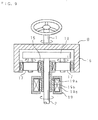
- FIG. 7 is a schematic view showing a construction of a rotation transmitting apparatus according to Embodiment 1 of the present invention.
- FIG. 8 is a cross sectional view taken along the line II-II of FIG. 7.
- the rotation transmitting apparatus comprises a differential gears mechanism A which includes a first shaft 1 and a second shaft 2 arranged coaxially so as to be freely rotatable, a first sun gear 3 coupled to the first shaft 1 coaxially so as to rotate interlockingly, a second sun gear 4 coupled to the second shaft 2 coaxially so as to rotate interlockingly, a plurality of first planetary gears 5 meshed with the first sun gear 3, a plurality of second planetary gears 6 rotating coaxially with the first planetary gears 5 and meshed with the second sun gear 4, and a carrier 7 supporting the first and second planetary gears 5 and 6, an external toothed member 8 mounted on the outer surface of the carrier 7, a differential electric motor 10 having a first drive gear 9 meshed with teeth of the external toothed member 8 and acting as an actuator for rotating the carrier 7, a transmission gear 11 mounted to an intermediate portion of the first shaft 1, and a reaction force electric motor 13 as a actuator having a second drive gear 12 meshed with the transmission gear 11 for applying a required
- Both the first shaft 1 and the second shaft 2 are rotatably mounted through bearings to a stationary member and first and second sun gears 3 and 4 come opposite to each other along the same axis.
- a torque sensor is provided on the periphery of the first shaft 1 for detecting the torque applied to the first shaft 1 and a controller 14 is provided for controlling the action of drive circuits 10a and 13a of the differential electric motor 10 and the reaction force electric motor 13 respectively based on the torque detected by the torque sensor, or the like.
- the carrier 7 includes a first plate portion 7a of a disc shape rotatably supportably fitted onto the outer surface of the first shaft 1, a second plate portion 7b of a disc shape rotatably supportably fitted onto the outer surface of the second shaft 2, and an annular joint portion 7c joining at the outer surface between the first plate portion 7a and the second plate portion 7b.
- the external toothed member 8 of an annular shape having a plurality of teeth is integrally mounted onto the outer surface of the annular joint portion 7c.
- the first planetary gears 5 are uniformly allocated at a plurality of peripheral positions of the first plate portion 7a while the second planetary gears 6 are uniformly allocated at a plurality of peripheral positions of the second plate portion 7b.
- the first and second planetary gears 5 and 6 are mounted on both longitudinal ends of a single shaft member.
- the first and second planetary gears 5 and 6 of the differential gears mechanism A and the first and second sun gears 3 and 4 all are constituted of spur gears. It is assumed that the number of teeth Z1 of the first sun gear 3 is 17, the number of teeth Z2 of the first planetary gear 5 is 15, the number of teeth Z3 of the second planetary gear 6 is 13, and the number of teeth Z4 of the second sun gear 4 is 19.
- the ratio of the torque applied to the second shaft 2 to the torque applied to the first shaft 1 is calculated from: ( Z 1 ⁇ Z 2 ) ⁇ ( Z 3 ⁇ Z 4 ) .
- the torque ratio is set to range from 1:0.7 to 1:0.9, which can obtain an optimal characteristic from the four characteristics shown in FIGS. 3 to 6.
- the torque ratio exceeds 1:0.9, the rotational speed of the carrier 7 will be higher than 2000 r/min thus generating a noise sound easily due to the rotation of the carrier 7.
- the torque ratio remains not higher than 1:0.9, the rotational speed of the carrier 7 is not higher than 2000 r/min and its generating noise sound in the differential gears mechanism will be attenuated.
- the rotational speed of the differential electric motor 10 when the torque ratio is lower than 1:0.7, the rotational speed of the differential electric motor 10 will relatively increase thus deteriorating the operational response and increasing a noise sound. If the torque ratio exceeds 1:1.0, the differential electric motor 10 may rotate in a reverse direction during the gear-ratio variable steering action. Since the torque ratio is ranged from 1:0.7 to 1:0.9, the rotational speed of the differential electric motor 10 can relatively be lowered, the differential electric motor 10 can be driven while operated without its rotational direction reversed, hence preventing the steering feeling from deteriorating by any unfavorable sense of motion.
- both the differential electric motor 10 and the reaction force electric motor 13 will be relatively increased in the power consumption. Since the torque ratio remains in a range from 1:0.7 to 1:0.9, both the electric motors 10 and 13 can stay low in the output and thus be decreased in the power consumption.
- the rotation transmitting apparatus equipped with a differential gears mechanism A is commonly used as a steering apparatus in a vehicle.
- the steering apparatus is constructed in a manner such that the first shaft 1 is joined to the steering wheel of the vehicle, a steering mechanism includes a pinion gear and a rack shaft which is provided with a rack gear meshed with the pinion gear and which enables its movement in the axial direction, and the second shaft 2 is joined to the pinion gear in the steering mechanism so as to rotate interlockingly, thus conducting the action of steering control wheels mounted to both ends of the rack shaft.
- the controller 14 provides the drive circuit 10a with a command signal for driving the differential electric motor 10 of which the rotating action is transmitted via the drive gear 9 and the external toothed member 8 to the carrier 7 which in turn rotates to turn the first and second planetary gears 5 and 6 and the second sun gear 4 and thus increase the rotational speed of the second shaft 2.
- the controller 14 supplies the drive circuit 13a with a command signal for driving the reaction force electric motor 13 in response to a torque applied to the second shaft 2 or the like.
- a reaction force torque for example, in the same direction as the rotational direction of the first shaft 1, is applied to the first shaft 1, thus returning its steering torque to the correct level.
- FIG. 9 is a schematic view showing a construction of a rotation transmitting apparatus according to Embodiment 2 of the present invention.
- the rotation transmitting apparatus comprises a differential gears mechanism B which includes a first shaft 1 and a second shaft 2 arranged coaxially so as to be freely rotatable, a sun gear 15 rotatably fitted and mounted on the second shaft 2, an internal gear 16 arranged on the periphery of the sun gear 15 so as to be freely rotatable and coupled to the first shaft 1 coaxially so as to rotate interlockingly, a plurality of planetary gears 17 meshed with the sun gear 15 and the internal gear 16, and a carrier 18 supporting the planetary gears 17 and coupled with the second shaft 2 coaxially so as to rotate interlockingly and a differential electric motor 19 as an actuator arranged on the periphery of the second shaft 2.
- a cylindrical rotor 19a of the differential electric motor 19 is joined to the sun gear 15 coaxially so as to rotate interlockingly.
- the internal gear 16 is formed in a cylindrical bottomed shape having a set of teeth mounted on the inner side thereof.
- the first shaft 1 is coupled in the center of the bottom of the internal gear 16.
- the sun gear 15 is formed integral with the rotor 19a as a movable portion, and a permanent magnet 19b is mounted on the outer surface of the rotor 19a and is surrounded by a stator 19c of the electric motor 19.
- the carrier 18 is formed in a disk shape.
- a pair of the planetary gears 17 are symmetrically mounted at two deflected locations from the center of the carrier 18.
- the sun gear 15, the internal gear 16, and the planetary gears 17 in the differential gears mechanism B are constituted of spur gears. It is assumed that the number of teeth Z5 of the sun gear 15 is 11 while the number of teeth Z6 of the internal gear 16 is 45.
- the ratio of the torque applied to the second shaft 2 to the torque applied to the first shaft 1 is calculated from: Z 6 / ( Z 6 + Z 5 ) .
- the torque ratio is set to range from 1:0.7 to 1:0.9, which can obtain an optimal characteristic from the four characteristics shown in FIGS. 3 to 6.
- Embodiment 2 when the first shaft 1 is turned by the action of the steering wheel, its movement is transmitted via the internal gear 16, the planetary gears 17, and the carrier 18 to the second shaft 2. Moreover, the controller provides the drive circuit with a command signal for driving the differential electric motor 19 of which the rotating action is transmitted via the sun gear 15 and the planetary gears 17 to the carrier 18 which in turn rotates to increase the rotational speed of the second shaft 2.
- Embodiment 2 Although a reaction force electric motor is not illustrated in Embodiment 2, another structure may also be employed for Embodiment 2 in which the transmission gear is provided in the middle of the first shaft 1 as in Embodiment 1, and a reaction force electric motor having a drive gear meshing with the transmission gear are provided, and applying a required torque force to the first shaft 1 in response to a torque which has been applied to the second shaft 2 when the steering torque applied to the first shaft 1 is deviated from its correct steering torque.
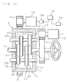
- FIG. 10 is a schematic view showing a construction of a rotation transmitting apparatus according to Embodiment 3 of the present invention.
- the rotation transmitting apparatus comprises a differential mechanism C having no gear in place of the differential gears mechanism A.
- the rotation transmitting apparatus comprises the differential mechanism C which includes two, first and second, sun pulleys 20 and 21 corresponding to the first and second sun gears 3 and 4, two, first and second, planetary pulleys 22 and 23 corresponding to the first and second planetary gears 5 and 6, a first transmission belt 24 mounted between the first sun pulley 20 and the first planetary pulley 22, a second transmission belt 25 mounted between the second sun pulley 21 and the second planetary pulley 23, and a carrier 7 arranged rotatably supporting the first and second planetary pulleys 22 and 23, a differential electric motor 10 provided as an actuator for driving the rotating motion of the carrier 7, and a reaction force electric motor 13 provided as an actuator for applying a required torque to the first shaft 1 in response to the torque applied to the second shaft 2 when
- the first sun pulley 20 is joined coaxially with the first shaft 1 so as to rotate interlockingly while the second sun pulley 21 is joined coaxially with the second shaft 2 so as to rotate interlockingly.
- the two, first and second, planetary pulleys 22 and 23 are integrally mounted on the same shaft.
- the ratio of the torque applied to the second shaft 2 to the torque applied to the first shaft 1 during transmission of the rotating motion from the first shaft 1 to the second shaft 2 is calculated from: ( D 1 ⁇ D 2 ) ⁇ ( D 3 ⁇ D 4 ) .
- the torque ratio is set to range from 1:0.7 to 1:0.9, which can obtain an optimal characteristic from the four characteristics shown in FIGS. 3 to 6.
- Embodiment 3 when the first shaft 1 is turned, its movement is transmitted via the first sun pulley 20, the first and second planetary pulleys 22 and 23, and the second sun pulley 21 to the second shaft 2 which is thus turned. Moreover, the controller 14 provides the drive circuit 10a with a command signal for driving the differential electric motor 10 of which the rotating action is transmitted via the drive gear 9 and the external toothed member 8 to the carrier 7 which in turn rotates to turn the first and second planetary pulleys 22 and 23 and the second sun pulley 21 and thus increase the rotational speed of the second shaft 2.
- the controller 14 supplies the drive circuit 13a with a command signal for driving the reaction force electric motor 13 in response to a torque applied to the second shaft 2 or the like.
- a reaction force torque for example, in the same direction as the rotational direction of the first shaft 1, is applied to the first shaft 1, thus returning its steering torque to the correct level.
- the electric motors 10 and 13 are used as the actuators for the differential and the counter action in the above embodiments but intended not to be so limited.
- reaction force electric motor 13 may be eliminated if not needed.
- the differential electric motor 10 is arranged for rotating the carrier 7 in Embodiment 1, it may rotate directly the second shaft 2.
- the differential electric motor 19 is arranged for driving the sun gear 15 with the first shaft 1 joined to the internal gear 16 and the second shaft 2 joined to the carrier 18 so as to rotate interlockingly.
- the carrier 18 may be joined to the rotator 19a of the differential electric motor 19 so as to rotate interlockingly and driven by the differential electric motor 19.
- the internal gear 16 may be joined to the rotator 19a of the differential electric motor 19 so as to rotate interlockingly and driven by the differential electric motor 19.
- the internal gear 16 may be joined to the rotator 19a of the differential electric motor 19 so as to rotate interlockingly and driven by the differential electric motor 19.
- V belts are used as the transmission belts in Embodiment 3
- V belts, toothed belts, or the like may also be used.
Landscapes
- Engineering & Computer Science (AREA)
- Chemical & Material Sciences (AREA)
- Combustion & Propulsion (AREA)
- Transportation (AREA)
- Mechanical Engineering (AREA)
- Power Steering Mechanism (AREA)
- Retarders (AREA)
- Transmission Devices (AREA)
Applications Claiming Priority (1)
| Application Number | Priority Date | Filing Date | Title |
|---|---|---|---|
| JP2005066197A JP4626345B2 (ja) | 2005-03-09 | 2005-03-09 | 車両のステアリング装置 |
Publications (3)
| Publication Number | Publication Date |
|---|---|
| EP1700772A2 true EP1700772A2 (de) | 2006-09-13 |
| EP1700772A3 EP1700772A3 (de) | 2006-12-13 |
| EP1700772B1 EP1700772B1 (de) | 2010-06-09 |
Family
ID=36579557
Family Applications (1)
| Application Number | Title | Priority Date | Filing Date |
|---|---|---|---|
| EP06110778A Ceased EP1700772B1 (de) | 2005-03-09 | 2006-03-07 | Kraftfahrzeuglenkung ausgestattet mit einer Einrichtung zur Übertragung einer Drehbewegung |
Country Status (4)
| Country | Link |
|---|---|
| US (1) | US7678004B2 (de) |
| EP (1) | EP1700772B1 (de) |
| JP (1) | JP4626345B2 (de) |
| DE (1) | DE602006014747D1 (de) |
Cited By (1)
| Publication number | Priority date | Publication date | Assignee | Title |
|---|---|---|---|---|
| CN111664226A (zh) * | 2019-03-05 | 2020-09-15 | 通用电气公司 | 用于涡轮机的换向齿轮组件 |
Families Citing this family (13)
| Publication number | Priority date | Publication date | Assignee | Title |
|---|---|---|---|---|
| JP4936052B2 (ja) * | 2006-09-25 | 2012-05-23 | 株式会社ジェイテクト | 車両用操舵装置 |
| DE602007007764D1 (de) * | 2006-05-22 | 2010-08-26 | Vestas Wind Sys As | Getriebesystem für eine windturbine |
| JP2010540844A (ja) * | 2007-10-09 | 2010-12-24 | コーヨー ベアリングス ユーエスエイ、エルエルシー | 非同期ベルト駆動カムシャフト位相シフト装置 |
| US20090133953A1 (en) * | 2007-11-28 | 2009-05-28 | Delphi Technologies, Inc. | Power steering system having a variable-ratio drive mechanism for a vehicle |
| CN101654116B (zh) * | 2008-08-19 | 2011-12-14 | 上海通用汽车有限公司 | 一种用于汽车转向器传动比调试的行星齿轮机构 |
| US8096917B2 (en) * | 2008-11-13 | 2012-01-17 | General Electric Company | Planetary gearbox having multiple sun pinions |
| SE534469C2 (sv) * | 2010-01-11 | 2011-09-06 | Scania Cv Ab | Anordning för aktiv styrning av ett lastfordon och styrinrättning med sådan anordning |
| CN103253297B (zh) * | 2013-05-29 | 2015-11-18 | 长城汽车股份有限公司 | 用于车辆的转向系统及具有该转向系统的车辆 |
| NL2014868B1 (nl) * | 2015-05-27 | 2017-01-02 | Jpm Beheer B V | Reddingsgereedschap. |
| KR101806682B1 (ko) * | 2016-04-12 | 2017-12-07 | 현대자동차주식회사 | 차량의 어댑티브 프론트 스티어링 시스템 |
| KR102657328B1 (ko) | 2016-11-23 | 2024-04-15 | 현대자동차주식회사 | 스티어 바이 와이어 시스템용 조향장치 |
| CN111315636B (zh) * | 2017-11-10 | 2022-02-25 | 赛迈道依茨-法尔意大利股份公司 | 车辆的液压转向系统的调节组件 |
| CN108167402A (zh) * | 2018-02-02 | 2018-06-15 | 江苏南自通华电力自动化股份有限公司 | 一种大功率节能型行星齿轮调速驱动系统 |
Citations (1)
| Publication number | Priority date | Publication date | Assignee | Title |
|---|---|---|---|---|
| JPS61122071A (ja) | 1984-11-19 | 1986-06-10 | Mazda Motor Corp | 自動車のステアリング装置 |
Family Cites Families (22)
| Publication number | Priority date | Publication date | Assignee | Title |
|---|---|---|---|---|
| US2465739A (en) * | 1943-10-26 | 1949-03-29 | Donald W Green | Power transmission device |
| US3052098A (en) * | 1955-03-21 | 1962-09-04 | Ebert Heinrich | Hydrostatic axial piston fluid transmission |
| JPS60209362A (ja) * | 1984-04-02 | 1985-10-21 | Nissan Motor Co Ltd | ステアリングギヤ装置 |
| JPS61122074A (ja) | 1984-11-19 | 1986-06-10 | Mazda Motor Corp | 自動車のステアリング装置 |
| JPS61122077A (ja) | 1984-11-19 | 1986-06-10 | Mazda Motor Corp | 自動車のステアリング装置 |
| JPS61122073A (ja) | 1984-11-19 | 1986-06-10 | Mazda Motor Corp | 自動車のステアリング装置 |
| JPS61122075A (ja) | 1984-11-19 | 1986-06-10 | Mazda Motor Corp | 自動車のステアリング装置 |
| JPS61122072A (ja) | 1984-11-19 | 1986-06-10 | Mazda Motor Corp | 自動車のステアリング装置 |
| JPS61122076A (ja) | 1984-11-19 | 1986-06-10 | Mazda Motor Corp | 自動車のステアリング装置 |
| JPS61166772A (ja) * | 1985-01-21 | 1986-07-28 | Nissan Motor Co Ltd | 車両用操舵装置 |
| JPS61161170U (de) * | 1985-03-29 | 1986-10-06 | ||
| JPH0577751A (ja) * | 1991-09-17 | 1993-03-30 | Fuji Heavy Ind Ltd | 車両用ステアリング制御装置 |
| JPH11171034A (ja) * | 1997-12-10 | 1999-06-29 | Toyota Motor Corp | 車両用操舵装置 |
| US6213242B1 (en) * | 1998-08-31 | 2001-04-10 | Ashok Rodrigues | Four wheel drive system having torque distribution control responsive to throttle position, speed and selected range |
| US6159124A (en) * | 1999-03-31 | 2000-12-12 | Daimlerchrysler Corporation | Hydraulic control system for automatic transmission with energy saving logic mode |
| US6461265B1 (en) * | 2000-02-02 | 2002-10-08 | Ex-Cello Machine Tools, Inc. | Coaxial gear box |
| US6575265B2 (en) * | 2000-03-30 | 2003-06-10 | Delphi Technologies, Inc. | Linear differential assisted controlled steering |
| JP2003294091A (ja) * | 2002-04-02 | 2003-10-15 | Honda Motor Co Ltd | 差動ギヤ式変速装置 |
| JP2003294092A (ja) * | 2002-04-02 | 2003-10-15 | Honda Motor Co Ltd | 差動ギヤ式変速装置 |
| JP4106990B2 (ja) * | 2002-07-12 | 2008-06-25 | 株式会社ジェイテクト | 車両用操舵装置 |
| WO2005115819A1 (ja) * | 2004-05-31 | 2005-12-08 | Jtekt Corporation | 車両用操舵装置 |
| EP1693599B1 (de) * | 2005-02-16 | 2011-06-22 | Jtekt Corporation | Fahrzeuglenkvorrichtung |
-
2005
- 2005-03-09 JP JP2005066197A patent/JP4626345B2/ja not_active Expired - Fee Related
-
2006
- 2006-03-07 DE DE602006014747T patent/DE602006014747D1/de not_active Expired - Lifetime
- 2006-03-07 EP EP06110778A patent/EP1700772B1/de not_active Ceased
- 2006-03-08 US US11/369,932 patent/US7678004B2/en not_active Expired - Fee Related
Patent Citations (1)
| Publication number | Priority date | Publication date | Assignee | Title |
|---|---|---|---|---|
| JPS61122071A (ja) | 1984-11-19 | 1986-06-10 | Mazda Motor Corp | 自動車のステアリング装置 |
Cited By (1)
| Publication number | Priority date | Publication date | Assignee | Title |
|---|---|---|---|---|
| CN111664226A (zh) * | 2019-03-05 | 2020-09-15 | 通用电气公司 | 用于涡轮机的换向齿轮组件 |
Also Published As
| Publication number | Publication date |
|---|---|
| EP1700772A3 (de) | 2006-12-13 |
| US20060205551A1 (en) | 2006-09-14 |
| JP2006248339A (ja) | 2006-09-21 |
| JP4626345B2 (ja) | 2011-02-09 |
| DE602006014747D1 (de) | 2010-07-22 |
| EP1700772B1 (de) | 2010-06-09 |
| US7678004B2 (en) | 2010-03-16 |
Similar Documents
| Publication | Publication Date | Title |
|---|---|---|
| EP1700772B1 (de) | Kraftfahrzeuglenkung ausgestattet mit einer Einrichtung zur Übertragung einer Drehbewegung | |
| JP3950456B2 (ja) | 遊星ローラ式無段変速機 | |
| JP2009061836A (ja) | 舵角可変式ステアリング装置 | |
| JP2002235832A (ja) | 減速機付き差動装置 | |
| US7244214B2 (en) | Speed change device and steering system | |
| JPH07198002A (ja) | 変速装置 | |
| JP7365714B2 (ja) | 回転式変速機構 | |
| EP1903254B1 (de) | Lenkvorrichtung für ein Fahrzeug | |
| US5474504A (en) | Asymmetric planetary gear variable speed transmission | |
| JP2949604B2 (ja) | 電動式動力舵取装置 | |
| JP4428100B2 (ja) | ステアリング装置 | |
| KR20070064978A (ko) | 모터드리븐 파워스티어링 시스템의 동력전달구조 | |
| US20040002403A1 (en) | Drive transmission | |
| JP2006264411A (ja) | 車両用操舵装置 | |
| EP1604129A1 (de) | Vorwärts-rückwärts-steuervorrichtung | |
| JP2002257204A (ja) | 旋回制御歯車式自動無段変速機 | |
| JP4802504B2 (ja) | 変速装置およびそれを用いた車両用可変舵角装置 | |
| JP2006290250A (ja) | 車輌用可変舵角装置 | |
| KR20010011512A (ko) | 평행축 기어의 백-래시 조절구조 및 그 방법 | |
| JPS63214544A (ja) | 変速機構 | |
| JP4734945B2 (ja) | 車両用操舵装置 | |
| JP2006290249A (ja) | 車輌用可変舵角装置 | |
| JP2006290252A (ja) | 車輌用可変舵角装置 | |
| JP4072530B2 (ja) | パワースプリット型無段変速装置 | |
| KR101946193B1 (ko) | 다중의 힘을 누적하여 단일의 힘으로 출력하거나 다중의 변위를 누적하여 단일의 변위로 출력하는 장치 |
Legal Events
| Date | Code | Title | Description |
|---|---|---|---|
| PUAI | Public reference made under article 153(3) epc to a published international application that has entered the european phase |
Free format text: ORIGINAL CODE: 0009012 |
|
| AK | Designated contracting states |
Kind code of ref document: A2 Designated state(s): AT BE BG CH CY CZ DE DK EE ES FI FR GB GR HU IE IS IT LI LT LU LV MC NL PL PT RO SE SI SK TR |
|
| AX | Request for extension of the european patent |
Extension state: AL BA HR MK YU |
|
| PUAL | Search report despatched |
Free format text: ORIGINAL CODE: 0009013 |
|
| AK | Designated contracting states |
Kind code of ref document: A3 Designated state(s): AT BE BG CH CY CZ DE DK EE ES FI FR GB GR HU IE IS IT LI LT LU LV MC NL PL PT RO SE SI SK TR |
|
| AX | Request for extension of the european patent |
Extension state: AL BA HR MK YU |
|
| 17P | Request for examination filed |
Effective date: 20070605 |
|
| 17Q | First examination report despatched |
Effective date: 20070711 |
|
| AKX | Designation fees paid |
Designated state(s): DE FR GB |
|
| GRAP | Despatch of communication of intention to grant a patent |
Free format text: ORIGINAL CODE: EPIDOSNIGR1 |
|
| RTI1 | Title (correction) |
Free format text: STEERING APPARATUS IN A VEHICLE PROVIDED WITH A ROTATION TRANSMITTING APPARATUS |
|
| GRAS | Grant fee paid |
Free format text: ORIGINAL CODE: EPIDOSNIGR3 |
|
| GRAA | (expected) grant |
Free format text: ORIGINAL CODE: 0009210 |
|
| AK | Designated contracting states |
Kind code of ref document: B1 Designated state(s): DE FR GB |
|
| REF | Corresponds to: |
Ref document number: 602006014747 Country of ref document: DE Date of ref document: 20100722 Kind code of ref document: P |
|
| PLBE | No opposition filed within time limit |
Free format text: ORIGINAL CODE: 0009261 |
|
| STAA | Information on the status of an ep patent application or granted ep patent |
Free format text: STATUS: NO OPPOSITION FILED WITHIN TIME LIMIT |
|
| 26N | No opposition filed |
Effective date: 20110310 |
|
| REG | Reference to a national code |
Ref country code: DE Ref legal event code: R097 Ref document number: 602006014747 Country of ref document: DE Effective date: 20110309 |
|
| GBPC | Gb: european patent ceased through non-payment of renewal fee |
Effective date: 20110307 |
|
| PG25 | Lapsed in a contracting state [announced via postgrant information from national office to epo] |
Ref country code: GB Free format text: LAPSE BECAUSE OF NON-PAYMENT OF DUE FEES Effective date: 20110307 |
|
| REG | Reference to a national code |
Ref country code: FR Ref legal event code: PLFP Year of fee payment: 10 |
|
| REG | Reference to a national code |
Ref country code: FR Ref legal event code: PLFP Year of fee payment: 11 |
|
| REG | Reference to a national code |
Ref country code: FR Ref legal event code: PLFP Year of fee payment: 12 |
|
| REG | Reference to a national code |
Ref country code: FR Ref legal event code: PLFP Year of fee payment: 13 |
|
| PGFP | Annual fee paid to national office [announced via postgrant information from national office to epo] |
Ref country code: DE Payment date: 20190219 Year of fee payment: 14 |
|
| PGFP | Annual fee paid to national office [announced via postgrant information from national office to epo] |
Ref country code: FR Payment date: 20190213 Year of fee payment: 14 |
|
| REG | Reference to a national code |
Ref country code: DE Ref legal event code: R119 Ref document number: 602006014747 Country of ref document: DE |
|
| PG25 | Lapsed in a contracting state [announced via postgrant information from national office to epo] |
Ref country code: FR Free format text: LAPSE BECAUSE OF NON-PAYMENT OF DUE FEES Effective date: 20200331 Ref country code: DE Free format text: LAPSE BECAUSE OF NON-PAYMENT OF DUE FEES Effective date: 20201001 |