EP1700800A1 - Vorrichtung zum Transportieren von klebrigem und/oder feuchtem Material - Google Patents
Vorrichtung zum Transportieren von klebrigem und/oder feuchtem Material Download PDFInfo
- Publication number
- EP1700800A1 EP1700800A1 EP05101924A EP05101924A EP1700800A1 EP 1700800 A1 EP1700800 A1 EP 1700800A1 EP 05101924 A EP05101924 A EP 05101924A EP 05101924 A EP05101924 A EP 05101924A EP 1700800 A1 EP1700800 A1 EP 1700800A1
- Authority
- EP
- European Patent Office
- Prior art keywords
- screw
- shaftless spiral
- trough
- pipe
- spiral
- Prior art date
- Legal status (The legal status is an assumption and is not a legal conclusion. Google has not performed a legal analysis and makes no representation as to the accuracy of the status listed.)
- Withdrawn
Links
- 239000000463 material Substances 0.000 title claims abstract description 24
- 238000007599 discharging Methods 0.000 claims abstract 2
- 239000010802 sludge Substances 0.000 description 15
- 239000010801 sewage sludge Substances 0.000 description 2
- 241000219310 Beta vulgaris subsp. vulgaris Species 0.000 description 1
- 229920006798 HMWPE Polymers 0.000 description 1
- 229910000760 Hardened steel Inorganic materials 0.000 description 1
- 239000004705 High-molecular-weight polyethylene Substances 0.000 description 1
- 229910000831 Steel Inorganic materials 0.000 description 1
- 235000021536 Sugar beet Nutrition 0.000 description 1
- XAGFODPZIPBFFR-UHFFFAOYSA-N aluminium Chemical compound [Al] XAGFODPZIPBFFR-UHFFFAOYSA-N 0.000 description 1
- 229910052782 aluminium Inorganic materials 0.000 description 1
- 239000004411 aluminium Substances 0.000 description 1
- 230000000694 effects Effects 0.000 description 1
- 239000010815 organic waste Substances 0.000 description 1
- 229920002635 polyurethane Polymers 0.000 description 1
- 239000004814 polyurethane Substances 0.000 description 1
- 239000002990 reinforced plastic Substances 0.000 description 1
- 229910001220 stainless steel Inorganic materials 0.000 description 1
- 239000010935 stainless steel Substances 0.000 description 1
- 239000010959 steel Substances 0.000 description 1
Images
Classifications
-
- B—PERFORMING OPERATIONS; TRANSPORTING
- B65—CONVEYING; PACKING; STORING; HANDLING THIN OR FILAMENTARY MATERIAL
- B65G—TRANSPORT OR STORAGE DEVICES, e.g. CONVEYORS FOR LOADING OR TIPPING, SHOP CONVEYOR SYSTEMS OR PNEUMATIC TUBE CONVEYORS
- B65G33/00—Screw or rotary spiral conveyors
- B65G33/08—Screw or rotary spiral conveyors for fluent solid materials
- B65G33/14—Screw or rotary spiral conveyors for fluent solid materials comprising a screw or screws enclosed in a tubular housing
-
- B—PERFORMING OPERATIONS; TRANSPORTING
- B65—CONVEYING; PACKING; STORING; HANDLING THIN OR FILAMENTARY MATERIAL
- B65G—TRANSPORT OR STORAGE DEVICES, e.g. CONVEYORS FOR LOADING OR TIPPING, SHOP CONVEYOR SYSTEMS OR PNEUMATIC TUBE CONVEYORS
- B65G33/00—Screw or rotary spiral conveyors
- B65G33/24—Details
-
- B—PERFORMING OPERATIONS; TRANSPORTING
- B65—CONVEYING; PACKING; STORING; HANDLING THIN OR FILAMENTARY MATERIAL
- B65G—TRANSPORT OR STORAGE DEVICES, e.g. CONVEYORS FOR LOADING OR TIPPING, SHOP CONVEYOR SYSTEMS OR PNEUMATIC TUBE CONVEYORS
- B65G33/00—Screw or rotary spiral conveyors
- B65G33/24—Details
- B65G33/32—Adaptations of bearings or couplings for supporting and connecting screws
Definitions
- the invention concerns a device according to the preamble of claim 1.
- Such devices are known and are often used for transporting sludge such as sewage sludge with a dry matter content of 20-30%.
- the known devices have the disadvantage that if the trough is filled to a too high level the sticky and/or wet material often moves back through the opening in the centre of the shaftless spiral or screw and so limits the capacity of the device.
- the device is designed in accordance with the characterizing part of claim 1.
- the device is in accordance with claim 2. In this way all material transport through the opening in the centre of the shaftless spiral or screw is blocked.
- the device is in accordance with claim 3.
- the pipe cannot rotate and the surface of the pipe is stationary just like the surface of the trough. This gives an additional resistance to the material and prevents moving of the material with the shaft less spiral or screw, thereby preventing rotating of the material.
- the shaftless spiral or screw can move the material at a higher capacity or can move the material against an inclination.
- the device is in accordance with 4.
- the stiff shaftless spiral or screw can be mounted in an easy way in the trough.
- the device is in accordance with claim 5. In this way assembling of the device is easy as the shaft is in line with the outside diameter of the shaftless spiral or screw and needs no further bearings.
- the device is in accordance with claim 6. In this way the device can be used for transporting material upwards without need for additional equipment.
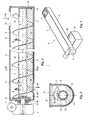
- FIGS 1, 2 and 3 show a conveyor 5 for transporting sludge 16 from an inlet opening 11 to an outlet opening 19.
- the conveyor consists of a U-shaped trough 4 with end plates, whereby the underside of the trough 4 is cylindrical.
- the liner 17 is made of material that causes low friction resistance, such as HMWPE, polyurethane or hardened steel bars.
- the liner 17 supports a shaftless spiral 3.
- the shaftless spiral 3 has a pitch S, an outside diameter D and an inside diameter d.
- the pitch S is equal to the outer diameter D and the inside diameter d is approximately 0,5 D.
- the length of the shaftless spiral 3 can be considerable and is at least 5 to 10 times the outer diameter D.
- the shaftless spiral 3 is made from plate with sufficient thickness so that the pitch S is more or less constant under load conditions and the spiral 3 keeps it shape over the length. This results in a robust, more or less unbendable and stiff shaftless spiral 3 of which the outside circumference is made so that it is supported over its whole length by the liner 17.
- the trough 4 is U shaped. It will be clear that other shapes are possible, such as a pipe shaped trough, as long as the underside of the trough is cylindrical. In most situations the shaftless spiral 3 and the trough 4 are made from steel, it is obvious for the skilled man that other materials can be used, such as aluminium, stainless steel and reinforced plastic materials.
- the shaftless spiral 3 ends in a flat plate that is coupled by bolts to a flange 8.
- the flange 8 is connected to a shaft 21 so that the shaft 21 has a centreline 9 in common with the shaftless spiral 3 and the liner 17.
- the shaft 21 is connected to a drive 1 which is mounted in such a way that it can rotate the shaft 21 and the shaftless spiral 3 in a direction of rotation R.
- a gasket 20 is mounted round the shaft 21 and attached to an end plate of the trough 4.
- the position of the drive 1 can be at the end of the trough 4 near the inlet opening 11 or at the end near the outlet opening 19.
- the diameter of the pipe 12 is such that it fits with a circular gap 22 inside the inner diameter d of the shaftless spiral 3.
- the length of pipe 12 is such that it encompasses approximately the whole length of the shaftless spiral 3.
- Shorter pipes 12 are possible whereby axial positioning means for the pipe 12 are installed.
- the pipe 12 can be free floating inside the shaftless spiral 3.
- the means for limiting the movement of the pipe 12 in the longitudinal direction can comprise a buffer 15 at the side of the outlet opening 19.
- the shaftless spiral 3 can be mounted in an easy way the trough 4 is open at the top.
- the disclosed embodiment has a cover 2, for instance in order to prevent that sludge 16 in the trough 4 dries out during stand still of the shaftless spiral 3 or for safety reasons.
- the cover 2 has an inlet opening 11 through which an inflow 10 of sludge 16 can fall in a known way into the through 4.
- the minimum value of the inflow 10 is chosen in combination with the speed of rotation of the shaftless spiral 3 in such a way that the average level of the sludge 16 remains under the top of the pipe 12.
- the pipe 12 thereby prevents that the sludge 16 moves through the opening in the inside diameter of the shaftless spiral 3, as occurs in designs without the pipe 12, and thereby makes a higher capacity of the conveyor 5 possible. This effect is obtained independently whether the pipe 12 rotates with the spiral 3 or not.
- the pipe 12 exerts friction on the sludge 16 in addition to the friction exerted by the liner 17. This added friction improves the working of the conveyor 5 by preventing rotating of the sludge 16 with the spiral 3.
- Such rotation of sludge would prevent transporting the sludge 16 in the longitudinal direction.
- the improvement by using the pipe 12 is especially important in situations where the through is filled to a high level with sludge 16 or where the conveyor 5 is used for transporting the sludge 16 upwards, for instance upwards under an angle of up to 15-20 degrees. Under special circumstances it is possible to transport the material under an angle of up to 90 degrees.
- the disclosed embodiment of the conveyor 5 with the pipe 12 is suitable for many applications and is especially suitable for transporting wet materials such as sewage sludge with dry matter content 20-30%, sugar beets pulp, and organic waste that can be transported over long distances without the risk that the sludge 16 starts to rotate with the shaftless spiral 3.
- wet materials such as sewage sludge with dry matter content 20-30%, sugar beets pulp, and organic waste that can be transported over long distances without the risk that the sludge 16 starts to rotate with the shaftless spiral 3.
- the invention can be applied to conveyors with a shaftless spiral or screw of completely different dimensions and materials, whereby the pitch S and the inside diameter d in relation to the outside diameter D can be adapted to different circumstances, the specific length of the trough and material to be transported. Also there can be more than one inlet opening 11 or more than one outlet opening 19.
Landscapes
- Engineering & Computer Science (AREA)
- Mechanical Engineering (AREA)
- Screw Conveyors (AREA)
- Control And Other Processes For Unpacking Of Materials (AREA)
- Electrical Discharge Machining, Electrochemical Machining, And Combined Machining (AREA)
- Paper (AREA)
Priority Applications (6)
| Application Number | Priority Date | Filing Date | Title |
|---|---|---|---|
| EP05101924A EP1700800A1 (de) | 2005-03-11 | 2005-03-11 | Vorrichtung zum Transportieren von klebrigem und/oder feuchtem Material |
| PCT/EP2006/050837 WO2006094872A1 (en) | 2005-03-11 | 2006-02-10 | Device for transporting sticky and/or wet material |
| EP06708180A EP1861325B1 (de) | 2005-03-11 | 2006-02-10 | Vorrichtung für den transport von klebrigem und/oder nassem material |
| AT06708180T ATE467588T1 (de) | 2005-03-11 | 2006-02-10 | Vorrichtung für den transport von klebrigem und/oder nassem material |
| DE602006014257T DE602006014257D1 (de) | 2005-03-11 | 2006-02-10 | Vorrichtung für den transport von klebrigem und/oder nassem material |
| US11/852,745 US7922384B2 (en) | 2005-03-11 | 2007-09-10 | Device for transporting sticky or wet material |
Applications Claiming Priority (1)
| Application Number | Priority Date | Filing Date | Title |
|---|---|---|---|
| EP05101924A EP1700800A1 (de) | 2005-03-11 | 2005-03-11 | Vorrichtung zum Transportieren von klebrigem und/oder feuchtem Material |
Publications (1)
| Publication Number | Publication Date |
|---|---|
| EP1700800A1 true EP1700800A1 (de) | 2006-09-13 |
Family
ID=34938957
Family Applications (2)
| Application Number | Title | Priority Date | Filing Date |
|---|---|---|---|
| EP05101924A Withdrawn EP1700800A1 (de) | 2005-03-11 | 2005-03-11 | Vorrichtung zum Transportieren von klebrigem und/oder feuchtem Material |
| EP06708180A Expired - Lifetime EP1861325B1 (de) | 2005-03-11 | 2006-02-10 | Vorrichtung für den transport von klebrigem und/oder nassem material |
Family Applications After (1)
| Application Number | Title | Priority Date | Filing Date |
|---|---|---|---|
| EP06708180A Expired - Lifetime EP1861325B1 (de) | 2005-03-11 | 2006-02-10 | Vorrichtung für den transport von klebrigem und/oder nassem material |
Country Status (5)
| Country | Link |
|---|---|
| US (1) | US7922384B2 (de) |
| EP (2) | EP1700800A1 (de) |
| AT (1) | ATE467588T1 (de) |
| DE (1) | DE602006014257D1 (de) |
| WO (1) | WO2006094872A1 (de) |
Cited By (7)
| Publication number | Priority date | Publication date | Assignee | Title |
|---|---|---|---|---|
| WO2009047811A1 (en) | 2007-10-10 | 2009-04-16 | Wam S.P.A. | Transport device |
| RU2443617C2 (ru) * | 2007-10-10 | 2012-02-27 | ВАМ С.п.А. | Транспортировочное устройство |
| CN102887340A (zh) * | 2012-10-25 | 2013-01-23 | 安徽宜桐机械有限公司 | 一种无轴螺旋输送机 |
| CN103112694A (zh) * | 2013-03-11 | 2013-05-22 | 张家港市浙华科技有限公司 | 一种生物质发电炉前螺旋输送机的装置 |
| CN103318623A (zh) * | 2013-05-22 | 2013-09-25 | 江西万申机械有限责任公司 | 螺旋式物料输送装置 |
| CN113199856A (zh) * | 2021-04-20 | 2021-08-03 | 凌剑强 | 一种包装纸箱印刷加工用烘干装置 |
| CN119160614A (zh) * | 2024-11-13 | 2024-12-20 | 江苏鹏飞集团股份有限公司 | 一种污泥处置再生陶粒的污泥无轴螺旋输送机 |
Families Citing this family (13)
| Publication number | Priority date | Publication date | Assignee | Title |
|---|---|---|---|---|
| CN102009826B (zh) * | 2010-12-09 | 2015-06-24 | 长兴日月环保机械有限公司 | 一种具有多联拼装结构的无轴螺旋输送机 |
| EP2789677A1 (de) | 2013-04-12 | 2014-10-15 | Kymi Baltic Consulting Oü | Torrefizierungsanlage, Betrieb und Wartung |
| US10028516B2 (en) | 2015-07-17 | 2018-07-24 | Wenger Manufacturing, Inc. | Apparatus and method for processing of high meat content food or feed products |
| CN107288560B (zh) * | 2017-07-17 | 2023-05-26 | 长江大学 | 一种具有泥浆过滤功能的螺旋输送装置 |
| CN107372151A (zh) * | 2017-08-16 | 2017-11-24 | 广东海翔教育科技有限公司 | 一种养猪用的环保节能喂料器 |
| CN107867544A (zh) * | 2017-12-05 | 2018-04-03 | 湖北惠泽生物科技股份有限公司 | 一种堵塞后自动停止运转的饲料输送系统 |
| CN108049439B (zh) * | 2017-12-23 | 2020-11-03 | 范赟东 | 一种双螺杆板抽泥装置 |
| JP2019210070A (ja) * | 2018-05-31 | 2019-12-12 | 日鉄テックスエンジ株式会社 | 搬送装置 |
| IT202000005155A1 (it) * | 2020-03-11 | 2021-09-11 | Wamgroup Spa | Dispositivo di trasporto, metodo di trasporto e sistema per il recupero di inerti. |
| WO2022235981A1 (en) * | 2021-05-06 | 2022-11-10 | Mason J Bradley | Systems and methods for treatment of materials |
| FR3129931B1 (fr) * | 2021-12-06 | 2024-04-19 | Rouages | Dispositif de transfert d’une matière solide avec vis sans fin et organe anti-rotation amovible |
| JP2023090283A (ja) * | 2021-12-17 | 2023-06-29 | 株式会社新光工業 | 無軸スクリュー搬送装置 |
| CN114313897B (zh) * | 2021-12-27 | 2023-12-05 | 南京辉航自动化设备有限公司 | 一种自清理粉体螺旋给料装置 |
Citations (3)
| Publication number | Priority date | Publication date | Assignee | Title |
|---|---|---|---|---|
| US3745856A (en) * | 1972-02-29 | 1973-07-17 | Resources Control Corp | Carousel indexing system for solid waste compactor |
| US6283275B1 (en) * | 1999-03-15 | 2001-09-04 | American Bulk Conveying Syst. | Screw and apparatus using same for conveying wet solids |
| US20020104739A1 (en) * | 2000-06-27 | 2002-08-08 | Tadao Yoshikawa | High-gradient high-pump-head screw conveyor device |
Family Cites Families (10)
| Publication number | Priority date | Publication date | Assignee | Title |
|---|---|---|---|---|
| US2009734A (en) * | 1934-02-03 | 1935-07-30 | Worthington Pump & Mach Corp | Chilling apparatus |
| US2847197A (en) * | 1951-08-31 | 1958-08-12 | Emery Thompson Machine & Suppl | Dasher means for frozen confections producing apparatus |
| US2835589A (en) * | 1954-11-23 | 1958-05-20 | Whitefield Bernard | Processing and means for caramelizing caramel, toffee and similar substances |
| US2836401A (en) * | 1956-08-16 | 1958-05-27 | Louis A M Phelan | Freezer scraper blade and mounting therefor |
| CA961789A (en) * | 1972-11-24 | 1975-01-28 | Macmillan Bloedel Research Limited | Screw conveyor for particulate material |
| DE2419952B2 (de) * | 1974-04-25 | 1976-06-24 | Henkel & Cie GmbH, 4000 Düsseldorf | Extruder zum herstellen eines zweifarbigen stranges |
| FR2414952A1 (fr) * | 1978-01-20 | 1979-08-17 | Ligouzat Pierre | Dispositif pour le melange continu de produits solides a l'etat divise et de produits liquides |
| US4383764A (en) * | 1981-05-12 | 1983-05-17 | Leon Sloin | Apparatus for continuous extrusion without reverse flow of material |
| IT1217923B (it) * | 1988-06-24 | 1990-03-30 | Ugolini Spa | Macchina perfezionata per la produzione di granita |
| GB2354471A (en) * | 1999-09-24 | 2001-03-28 | Univ Brunel | Producung semisolid metal slurries and shaped components therefrom |
-
2005
- 2005-03-11 EP EP05101924A patent/EP1700800A1/de not_active Withdrawn
-
2006
- 2006-02-10 EP EP06708180A patent/EP1861325B1/de not_active Expired - Lifetime
- 2006-02-10 WO PCT/EP2006/050837 patent/WO2006094872A1/en not_active Ceased
- 2006-02-10 AT AT06708180T patent/ATE467588T1/de not_active IP Right Cessation
- 2006-02-10 DE DE602006014257T patent/DE602006014257D1/de not_active Expired - Lifetime
-
2007
- 2007-09-10 US US11/852,745 patent/US7922384B2/en not_active Expired - Fee Related
Patent Citations (3)
| Publication number | Priority date | Publication date | Assignee | Title |
|---|---|---|---|---|
| US3745856A (en) * | 1972-02-29 | 1973-07-17 | Resources Control Corp | Carousel indexing system for solid waste compactor |
| US6283275B1 (en) * | 1999-03-15 | 2001-09-04 | American Bulk Conveying Syst. | Screw and apparatus using same for conveying wet solids |
| US20020104739A1 (en) * | 2000-06-27 | 2002-08-08 | Tadao Yoshikawa | High-gradient high-pump-head screw conveyor device |
Cited By (9)
| Publication number | Priority date | Publication date | Assignee | Title |
|---|---|---|---|---|
| WO2009047811A1 (en) | 2007-10-10 | 2009-04-16 | Wam S.P.A. | Transport device |
| US7934593B2 (en) | 2007-10-10 | 2011-05-03 | Wam Industriale S.P.A. | Transport device |
| RU2443617C2 (ru) * | 2007-10-10 | 2012-02-27 | ВАМ С.п.А. | Транспортировочное устройство |
| CN102887340A (zh) * | 2012-10-25 | 2013-01-23 | 安徽宜桐机械有限公司 | 一种无轴螺旋输送机 |
| CN103112694A (zh) * | 2013-03-11 | 2013-05-22 | 张家港市浙华科技有限公司 | 一种生物质发电炉前螺旋输送机的装置 |
| CN103318623A (zh) * | 2013-05-22 | 2013-09-25 | 江西万申机械有限责任公司 | 螺旋式物料输送装置 |
| CN113199856A (zh) * | 2021-04-20 | 2021-08-03 | 凌剑强 | 一种包装纸箱印刷加工用烘干装置 |
| CN113199856B (zh) * | 2021-04-20 | 2023-12-12 | 内蒙古和瑞包装有限公司 | 一种包装纸箱印刷加工用烘干装置 |
| CN119160614A (zh) * | 2024-11-13 | 2024-12-20 | 江苏鹏飞集团股份有限公司 | 一种污泥处置再生陶粒的污泥无轴螺旋输送机 |
Also Published As
| Publication number | Publication date |
|---|---|
| US7922384B2 (en) | 2011-04-12 |
| EP1861325A1 (de) | 2007-12-05 |
| DE602006014257D1 (de) | 2010-06-24 |
| ATE467588T1 (de) | 2010-05-15 |
| US20080067036A1 (en) | 2008-03-20 |
| WO2006094872A1 (en) | 2006-09-14 |
| EP1861325B1 (de) | 2010-05-12 |
Similar Documents
| Publication | Publication Date | Title |
|---|---|---|
| US7922384B2 (en) | Device for transporting sticky or wet material | |
| US4583903A (en) | Apparatus for bottom unloading of storage structures | |
| US12275604B2 (en) | Sweep system for full elevated floor grain bins | |
| AU4494089A (en) | A helical conveyor | |
| CN101659349A (zh) | 一种无轴螺旋输送机 | |
| KR20100003374A (ko) | 벌크 재료 펌프 피더 | |
| US6523667B1 (en) | Intermediate discharge for an enclosed roller belt conveyor assembly | |
| KR102276539B1 (ko) | 스크류 컨베이어의 역류방지장치 | |
| KR101294011B1 (ko) | 회전식 스크레이퍼가 구비된 슬러지용 사일로 | |
| KR20140078647A (ko) | 압축성 물질의 운반 및 이송 장치 | |
| US10836590B2 (en) | Grain bin unloading conveyor system | |
| EP1365978B1 (de) | Schneckenförderer mit zwei konzentrischen, achslosen schnecken | |
| CN115250764A (zh) | 一种用于翻动储粮的恒温粮仓 | |
| KR100713774B1 (ko) | 저류조의 슬러지 침전방지용 임펠러 | |
| US20110220462A1 (en) | Apparatus and Method for Conveying Cohesive Materials | |
| US1811719A (en) | Mixing machine | |
| CN215755356U (zh) | 一种污泥存储装置料仓结构及污泥存储装置 | |
| KR101773935B1 (ko) | 축 고정 스크류 이송 장치 | |
| KR100857279B1 (ko) | 탈수 케이크의 압송 장치 | |
| SK8626Y1 (sk) | Skrutkový dopravník najmä na dopravu odpadového materiálu pri čistení odpadových vôd | |
| RU228522U1 (ru) | Шнековый транспортер | |
| JPH10129827A (ja) | スクリューコンベヤ | |
| CN216995922U (zh) | 成品料仓 | |
| FI94081B (fi) | Palamaisen, raemaisen tai jauhemaisen materiaalin purkauslaite | |
| CN210594340U (zh) | 一种可快速供料的垃圾接收料仓系统 |
Legal Events
| Date | Code | Title | Description |
|---|---|---|---|
| PUAI | Public reference made under article 153(3) epc to a published international application that has entered the european phase |
Free format text: ORIGINAL CODE: 0009012 |
|
| AK | Designated contracting states |
Kind code of ref document: A1 Designated state(s): AT BE BG CH CY CZ DE DK EE ES FI FR GB GR HU IE IS IT LI LT LU MC NL PL PT RO SE SI SK TR |
|
| AX | Request for extension of the european patent |
Extension state: AL BA HR LV MK YU |
|
| STAA | Information on the status of an ep patent application or granted ep patent |
Free format text: STATUS: THE APPLICATION HAS BEEN WITHDRAWN |
|
| 17P | Request for examination filed |
Effective date: 20070313 |
|
| 18W | Application withdrawn |
Effective date: 20070320 |
|
| RIN1 | Information on inventor provided before grant (corrected) |
Inventor name: NEWMAN, RAYMOND C. Inventor name: VAN VOORTHUYSEN, GERRIT |