EP1700931A2 - Geschütztes Substrat mit einer eine Superlegierung enthaltenden Haftungschicht und einer mikrorissigen Wärmedämmschicht - Google Patents
Geschütztes Substrat mit einer eine Superlegierung enthaltenden Haftungschicht und einer mikrorissigen Wärmedämmschicht Download PDFInfo
- Publication number
- EP1700931A2 EP1700931A2 EP06250050A EP06250050A EP1700931A2 EP 1700931 A2 EP1700931 A2 EP 1700931A2 EP 06250050 A EP06250050 A EP 06250050A EP 06250050 A EP06250050 A EP 06250050A EP 1700931 A2 EP1700931 A2 EP 1700931A2
- Authority
- EP
- European Patent Office
- Prior art keywords
- percent
- substrate
- bond coat
- oxide
- protected article
- Prior art date
- Legal status (The legal status is an assumption and is not a legal conclusion. Google has not performed a legal analysis and makes no representation as to the accuracy of the status listed.)
- Withdrawn
Links
Images

Classifications
-
- C—CHEMISTRY; METALLURGY
- C23—COATING METALLIC MATERIAL; COATING MATERIAL WITH METALLIC MATERIAL; CHEMICAL SURFACE TREATMENT; DIFFUSION TREATMENT OF METALLIC MATERIAL; COATING BY VACUUM EVAPORATION, BY SPUTTERING, BY ION IMPLANTATION OR BY CHEMICAL VAPOUR DEPOSITION, IN GENERAL; INHIBITING CORROSION OF METALLIC MATERIAL OR INCRUSTATION IN GENERAL
- C23C—COATING METALLIC MATERIAL; COATING MATERIAL WITH METALLIC MATERIAL; SURFACE TREATMENT OF METALLIC MATERIAL BY DIFFUSION INTO THE SURFACE, BY CHEMICAL CONVERSION OR SUBSTITUTION; COATING BY VACUUM EVAPORATION, BY SPUTTERING, BY ION IMPLANTATION OR BY CHEMICAL VAPOUR DEPOSITION, IN GENERAL
- C23C4/00—Coating by spraying the coating material in the molten state, e.g. by flame, plasma or electric discharge
- C23C4/04—Coating by spraying the coating material in the molten state, e.g. by flame, plasma or electric discharge characterised by the coating material
- C23C4/06—Metallic material
- C23C4/08—Metallic material containing only metal elements
-
- C—CHEMISTRY; METALLURGY
- C23—COATING METALLIC MATERIAL; COATING MATERIAL WITH METALLIC MATERIAL; CHEMICAL SURFACE TREATMENT; DIFFUSION TREATMENT OF METALLIC MATERIAL; COATING BY VACUUM EVAPORATION, BY SPUTTERING, BY ION IMPLANTATION OR BY CHEMICAL VAPOUR DEPOSITION, IN GENERAL; INHIBITING CORROSION OF METALLIC MATERIAL OR INCRUSTATION IN GENERAL
- C23C—COATING METALLIC MATERIAL; COATING MATERIAL WITH METALLIC MATERIAL; SURFACE TREATMENT OF METALLIC MATERIAL BY DIFFUSION INTO THE SURFACE, BY CHEMICAL CONVERSION OR SUBSTITUTION; COATING BY VACUUM EVAPORATION, BY SPUTTERING, BY ION IMPLANTATION OR BY CHEMICAL VAPOUR DEPOSITION, IN GENERAL
- C23C28/00—Coating for obtaining at least two superposed coatings either by methods not provided for in a single one of groups C23C2/00 - C23C26/00 or by combinations of methods provided for in subclasses C23C and C25C or C25D
- C23C28/30—Coatings combining at least one metallic layer and at least one inorganic non-metallic layer
- C23C28/32—Coatings combining at least one metallic layer and at least one inorganic non-metallic layer including at least one pure metallic layer
- C23C28/321—Coatings combining at least one metallic layer and at least one inorganic non-metallic layer including at least one pure metallic layer with at least one metal alloy layer
- C23C28/3215—Coatings combining at least one metallic layer and at least one inorganic non-metallic layer including at least one pure metallic layer with at least one metal alloy layer at least one MCrAlX layer
-
- C—CHEMISTRY; METALLURGY
- C23—COATING METALLIC MATERIAL; COATING MATERIAL WITH METALLIC MATERIAL; CHEMICAL SURFACE TREATMENT; DIFFUSION TREATMENT OF METALLIC MATERIAL; COATING BY VACUUM EVAPORATION, BY SPUTTERING, BY ION IMPLANTATION OR BY CHEMICAL VAPOUR DEPOSITION, IN GENERAL; INHIBITING CORROSION OF METALLIC MATERIAL OR INCRUSTATION IN GENERAL
- C23C—COATING METALLIC MATERIAL; COATING MATERIAL WITH METALLIC MATERIAL; SURFACE TREATMENT OF METALLIC MATERIAL BY DIFFUSION INTO THE SURFACE, BY CHEMICAL CONVERSION OR SUBSTITUTION; COATING BY VACUUM EVAPORATION, BY SPUTTERING, BY ION IMPLANTATION OR BY CHEMICAL VAPOUR DEPOSITION, IN GENERAL
- C23C28/00—Coating for obtaining at least two superposed coatings either by methods not provided for in a single one of groups C23C2/00 - C23C26/00 or by combinations of methods provided for in subclasses C23C and C25C or C25D
- C23C28/30—Coatings combining at least one metallic layer and at least one inorganic non-metallic layer
- C23C28/32—Coatings combining at least one metallic layer and at least one inorganic non-metallic layer including at least one pure metallic layer
- C23C28/325—Coatings combining at least one metallic layer and at least one inorganic non-metallic layer including at least one pure metallic layer with layers graded in composition or in physical properties
-
- C—CHEMISTRY; METALLURGY
- C23—COATING METALLIC MATERIAL; COATING MATERIAL WITH METALLIC MATERIAL; CHEMICAL SURFACE TREATMENT; DIFFUSION TREATMENT OF METALLIC MATERIAL; COATING BY VACUUM EVAPORATION, BY SPUTTERING, BY ION IMPLANTATION OR BY CHEMICAL VAPOUR DEPOSITION, IN GENERAL; INHIBITING CORROSION OF METALLIC MATERIAL OR INCRUSTATION IN GENERAL
- C23C—COATING METALLIC MATERIAL; COATING MATERIAL WITH METALLIC MATERIAL; SURFACE TREATMENT OF METALLIC MATERIAL BY DIFFUSION INTO THE SURFACE, BY CHEMICAL CONVERSION OR SUBSTITUTION; COATING BY VACUUM EVAPORATION, BY SPUTTERING, BY ION IMPLANTATION OR BY CHEMICAL VAPOUR DEPOSITION, IN GENERAL
- C23C28/00—Coating for obtaining at least two superposed coatings either by methods not provided for in a single one of groups C23C2/00 - C23C26/00 or by combinations of methods provided for in subclasses C23C and C25C or C25D
- C23C28/30—Coatings combining at least one metallic layer and at least one inorganic non-metallic layer
- C23C28/34—Coatings combining at least one metallic layer and at least one inorganic non-metallic layer including at least one inorganic non-metallic material layer, e.g. metal carbide, nitride, boride, silicide layer and their mixtures, enamels, phosphates and sulphates
- C23C28/345—Coatings combining at least one metallic layer and at least one inorganic non-metallic layer including at least one inorganic non-metallic material layer, e.g. metal carbide, nitride, boride, silicide layer and their mixtures, enamels, phosphates and sulphates with at least one oxide layer
- C23C28/3455—Coatings combining at least one metallic layer and at least one inorganic non-metallic layer including at least one inorganic non-metallic material layer, e.g. metal carbide, nitride, boride, silicide layer and their mixtures, enamels, phosphates and sulphates with at least one oxide layer with a refractory ceramic layer, e.g. refractory metal oxide, ZrO2, rare earth oxides or a thermal barrier system comprising at least one refractory oxide layer
-
- Y—GENERAL TAGGING OF NEW TECHNOLOGICAL DEVELOPMENTS; GENERAL TAGGING OF CROSS-SECTIONAL TECHNOLOGIES SPANNING OVER SEVERAL SECTIONS OF THE IPC; TECHNICAL SUBJECTS COVERED BY FORMER USPC CROSS-REFERENCE ART COLLECTIONS [XRACs] AND DIGESTS
- Y02—TECHNOLOGIES OR APPLICATIONS FOR MITIGATION OR ADAPTATION AGAINST CLIMATE CHANGE
- Y02T—CLIMATE CHANGE MITIGATION TECHNOLOGIES RELATED TO TRANSPORTATION
- Y02T50/00—Aeronautics or air transport
- Y02T50/60—Efficient propulsion technologies, e.g. for aircraft
-
- Y—GENERAL TAGGING OF NEW TECHNOLOGICAL DEVELOPMENTS; GENERAL TAGGING OF CROSS-SECTIONAL TECHNOLOGIES SPANNING OVER SEVERAL SECTIONS OF THE IPC; TECHNICAL SUBJECTS COVERED BY FORMER USPC CROSS-REFERENCE ART COLLECTIONS [XRACs] AND DIGESTS
- Y10—TECHNICAL SUBJECTS COVERED BY FORMER USPC
- Y10T—TECHNICAL SUBJECTS COVERED BY FORMER US CLASSIFICATION
- Y10T428/00—Stock material or miscellaneous articles
- Y10T428/12—All metal or with adjacent metals
- Y10T428/12493—Composite; i.e., plural, adjacent, spatially distinct metal components [e.g., layers, joint, etc.]
- Y10T428/12535—Composite; i.e., plural, adjacent, spatially distinct metal components [e.g., layers, joint, etc.] with additional, spatially distinct nonmetal component
- Y10T428/12611—Oxide-containing component
- Y10T428/12618—Plural oxides
-
- Y—GENERAL TAGGING OF NEW TECHNOLOGICAL DEVELOPMENTS; GENERAL TAGGING OF CROSS-SECTIONAL TECHNOLOGIES SPANNING OVER SEVERAL SECTIONS OF THE IPC; TECHNICAL SUBJECTS COVERED BY FORMER USPC CROSS-REFERENCE ART COLLECTIONS [XRACs] AND DIGESTS
- Y10—TECHNICAL SUBJECTS COVERED BY FORMER USPC
- Y10T—TECHNICAL SUBJECTS COVERED BY FORMER US CLASSIFICATION
- Y10T428/00—Stock material or miscellaneous articles
- Y10T428/12—All metal or with adjacent metals
- Y10T428/12493—Composite; i.e., plural, adjacent, spatially distinct metal components [e.g., layers, joint, etc.]
- Y10T428/12736—Al-base component
- Y10T428/1275—Next to Group VIII or IB metal-base component
-
- Y—GENERAL TAGGING OF NEW TECHNOLOGICAL DEVELOPMENTS; GENERAL TAGGING OF CROSS-SECTIONAL TECHNOLOGIES SPANNING OVER SEVERAL SECTIONS OF THE IPC; TECHNICAL SUBJECTS COVERED BY FORMER USPC CROSS-REFERENCE ART COLLECTIONS [XRACs] AND DIGESTS
- Y10—TECHNICAL SUBJECTS COVERED BY FORMER USPC
- Y10T—TECHNICAL SUBJECTS COVERED BY FORMER US CLASSIFICATION
- Y10T428/00—Stock material or miscellaneous articles
- Y10T428/12—All metal or with adjacent metals
- Y10T428/12493—Composite; i.e., plural, adjacent, spatially distinct metal components [e.g., layers, joint, etc.]
- Y10T428/12771—Transition metal-base component
- Y10T428/12861—Group VIII or IB metal-base component
- Y10T428/12944—Ni-base component
Definitions
- This invention relates to the protection of materials used at high temperatures and, more particularly, to bond coat/ceramic thermal barrier coating systems used to protect components of gas turbine engines.
- gas turbine In an aircraft gas turbine (jet) engine, air is drawn into the front of the engine, compressed by a shaft-mounted compressor, and mixed with fuel. The mixture is burned to produce hot combustion gas.
- An annular stationary shroud forms a tunnel-like gas flow path through which the hot combustion gas passes.
- a gas turbine is located within the volume defined by the stationary shroud and is mounted on the same shaft as the compressor. The flow of combustion gas turns the gas turbine by impingement against an airfoil section of the turbine blades and vanes, which turns the shaft and provides power to the compressor and fan.
- the compressor and a high pressure turbine are mounted on one shaft, and the fan and low pressure turbine are mounted on a separate shaft.
- the hot combustion gas now an exhaust gas, flows from the back of the engine, driving it and the aircraft forward.
- the maximum temperature of the combustion gas is normally limited by the materials used to fabricate the stationary shroud and the turbine vanes and turbine blades of the turbine.
- the stationary shroud and the turbine vanes and blades are made of nickel-based superalloys, and can operate at temperatures of up to about 1038 - 1177°C (1900-2150°F).
- coatings are applied to the surface of the substrate to inhibit the oxidation of the substrate and to insulate the substrate, thereby permitting the substrate material to be used at a higher temperature than would otherwise be possible.
- the most widely used coatings are aluminum-rich layers whose surfaces oxidize to an aluminum oxide scale to inhibit further oxidation.
- the aluminum-rich layer may serve as either an environmental coating or as a bond coat under a thermal-insulator ceramic thermal barrier coating.
- Other types of coatings have also been used, although with less-satisfactory results.
- the present invention provides a protected article and method for preparing the protected article. This approach is most advantageously utilized for stationary gas-path components such as the turbine stationary shroud, but it may be utilized with other components such as turbine blades and turbine vanes as well.
- the protective system may be applied to the substrate by known techniques. This approach has been demonstrated to produce superior results to alternative approaches.
- a protected article comprises a substrate having a surface, and a protective system overlying and contacting a first portion of the surface of the substrate.
- the substrate is preferably a nickel-base superalloy such as a component of a gas turbine engine.
- the protective system comprises a bond coat comprising a layer of a nickel-base superalloy bond coat material contacting the surface of the substrate.
- the bond coat has a composition different from that of the substrate.
- An aluminide layer overlies and contacts the bond coat.
- a dense vertically microcracked ceramic thermal barrier coating overlies and contacts the aluminide layer.
- a preferred bond coat material has a nominal composition, in weight percent, of about 18 percent chromium, about 6.5 percent aluminum, about 10 percent cobalt, about 6 percent tantalum, about 2 percent rhenium, about 0.5 percent hafnium, about 0.3 percent yttrium, about 1 percent silicon, about 0.015 percent zirconium, about 0.015 percent boron, about 0.06 percent carbon, the balance nickel and incidental impurities.
- the bond coat preferably has a thermally sprayed microstructure.
- the aluminide layer preferably is a vapor-deposited diffusion aluminide.
- the ceramic thermal barrier coating preferably has a composition, in weight percent, of about 6 percent to about 9 percent yttrium oxide, a maximum of about 2.5 percent hafnium oxide, a maximum of about 1.5 percent silicon oxide, less than about 1 percent each of titanium oxide, iron oxide, calcium oxide, aluminum oxide, and magnesium oxide, less than about 2 weight percent total of other oxides, balance zirconium oxide and incidental impurities.
- the ceramic thermal barrier coating is applied so as to produce the dense vertically microcracked ceramic thermal barrier coating.
- a method for preparing a protected article comprises the steps of furnishing a substrate having a surface, and depositing a protective system overlying and contacting a first portion of the surface of the substrate.
- the protective system comprises a bond coat comprising a layer of a nickel-base superalloy bond coat material contacting the surface of the substrate, wherein the bond coat has a composition different from the substrate, an aluminide layer overlying and contacting the bond coat, and a dense vertically microcracked ceramic thermal barrier coating overlying and contacting the aluminide layer.
- the bond coat and the ceramic thermal barrier coating are preferably applied by thermal spraying, and the aluminide layer is preferably applied by vapor phase aluminiding. Other compatible features discussed herein may be used with this embodiment.
- the present approach improves the performance of the protective system utilizing the dense vertically microcracked ceramic thermal barrier coating.
- the superalloy bond coat and the aluminide layer, in combination with the dense vertically microcracked ceramic thermal barrier coating, produces improved oxidation resistance and other performance in simulated engine testing as compared with conventional thermal barrier coating systems.
- Figure 1 depicts a stationary shroud 20, in this case a stationary shroud for the high-pressure gas turbine of a gas turbine engine, and its shroud support 22 by which the stationary shroud 20 is supported from the remainder of the structure of the gas turbine engine.
- the stationary shroud 20 is formed of a plurality of stationary shroud segments extending around the circumference of the engine, creating an internal annular volume that defines a gas-flow-path 24. Additional features of the stationary shroud 20 and the shroud support 22, except for the protective structure disclosed below, are described in US Patent 6,233,822 .
- the preferred utilization of the present approach is with the turbine stationary shroud, but it may be used in other applications such as turbine blades, turbine vanes, and combustor components of gas turbine engines.
- a turbine blade 26 is supported on a rotating shaft (not shown) so that it rotates in a direction that takes it into and out of the plane of the illustration.
- a tip 28 of the turbine blade 26 faces a first portion 30 of a surface 32 of the stationary shroud 20.
- the first portion 30 is a hot-gas flow-path surface 31 of the stationary shroud 20, which is exposed to the hot combustion gas in the gas flow path 24.
- a second portion 34 of the surface 32 of the stationary shroud 20 is the non-flow-path surface 35 in this preferred embodiment, and constitutes at least part of the remainder of the surface 32 of the stationary shroud 20.
- the first portion 30 of the surface 32 is protected by a protective system 36 illustrated in Figure 2. ( Figures 2 and 3 are not drawn to scale.)
- the body of the stationary shroud 20 serves as a substrate 38 upon which the protective system 36 is deposited.
- the substrate 38 i.e., the stationary shroud 20
- the substrate 38 is preferably a cobalt-base superalloy, which has more cobalt than any other element, or a nickel-base alloy, which has more nickel than any other element.
- a preferred cobalt-base alloy is Mar-M-509TM, having a nominal composition in weight percent of about 23.5 percent chromium, about 10.0 percent nickel, about 7.0 percent tungsten, about 3.5 percent tantalum, about 0.6 percent carbon, about 0.5 percent zirconium, about 0.2 percent titanium, balance cobalt and minor elements.
- the substrate 38 even more preferably is a nickel-base superalloy, which in its heat-treated condition is strengthened by the presence of precipitates of gamma prime or a related phase.
- ReneTM N5 A preferred nickel-base superalloy is ReneTM N5, having a nominal composition in weight percent of about 7.5 percent cobalt, about 7.0 percent chromium, about 1.5 percent molybdenum, about 5 percent tungsten, about 3 percent rhenium, about 6.5 percent tantalum, about 6.2 percent aluminum, about 0.15 percent hafnium, about 0.05 percent carbon, about 0.004 percent boron, about 0.01 percent yttrium, balance nickel and minor elements, or ReneTM N2, having a nominal composition in weight percent as defined in US Patent Application 2004/0109786 .
- the protective system 36 overlies and contacts the first portion 30 of the surface 32 of the substrate 38, which in this case is the hot-gas flow-path surface 31.
- the protective system 36 comprises a bond coat 40, which itself is a layer of a nickel-base superalloy bond coat material that contacts the surface 32 of the substrate 38.
- the bond coat 40 has a composition different from that of the substrate 38.
- a first preferred bond coat material has a nominal composition, in weight percent, of about 18 percent chromium, about 6.5 percent aluminum, about 10 percent cobalt, about 6 percent tantalum, about 2 percent rhenium, about 0.5 percent hafnium, about 0.3 percent yttrium, about 1 percent silicon, about 0.015 percent zirconium, about 0.015 percent boron, about 0.06 percent carbon, the balance nickel and incidental impurities.
- a second preferred bond coat material has a nominal composition, in weight percent, of about 9 percent chromium, about 4 percent cobalt, about 6 percent aluminum, about 0.03 percent yttrium, about 5 percent tantalum, about 1.4 percent rhenium, about 4.5 percent tungsten, about 1.5 percent molybdenum, about 0.9 percent hafnium, about 0.5 percent carbon, balance nickel and incidental impurities.
- the bond coat 40 is preferably from about 0.0102 cm (0.004 inch) to about 0.059 cm (0.020 inch) thick.
- the protective system 36 further includes an aluminide layer overlying and contacting the bond coat 40.
- the aluminide layer 42 is preferably a diffusion aluminide such as a simple diffusion aluminide or a complex diffusion aluminide such as a platinum aluminide.
- the structure, composition, and method of application of simple and complex aluminides are discussed more fully in US Patent 6,607,611 .
- the aluminide layer is preferably from about 0.0013 cm (0.0005 inch) to about 0.0014 cm (0.0045 inch) thick.
- a dense vertically microcracked (DVM) ceramic thermal barrier coating (TBC) 48 overlies and contacts the aluminide layer 42.
- the DVM ceramic thermal barrier coating 48 preferably has a composition, in weight percent, of 6 percent to 9 percent yttrium oxide, a maximum of 2.5 percent hafnium oxide, a maximum of 1.5 percent silicon oxide, less than 1 percent each of titanium oxide, iron oxide, calcium oxide, aluminum oxide, and magnesium oxide, less than 2 weight percent total of other oxides, balance zirconium oxide and incidental impurities.
- the structure and application of the DVM TBC are discussed more fully in US Patents 5,520,516 ; 5,743,013 ; 5,879,753 ; and 6,180,262 .
- the DVM TBC 48 is preferably from about 0.0254 cm (0.010 inch) to about 0.203 cm (0.080 inch thick.
- the protective system 36 is applied to and protects only the first portion 30 of the surface 32 of the stationary shroud 20, which in the preferred embodiment is the hot-gas flow-path surface 31.
- a second protective system 50 as illustrated in Figure 3, may be used to protect this second portion 34 of the surface 32.
- a second aluminide layer overlies and contacts the second portion 34 of the surface 32, the non-flow-path surface in this case.
- the second protective system 50 has no bond coat and no thermal barrier coating.
- the second aluminide layer on the second portion 34 is the same aluminide layer 42 as on the first portion 30, as illustrated in Figure 3.
- other operable methods to protect the second portion 34 may be used as well.
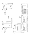
- Figure 4 is a flow chart depicting a preferred method for protecting an article substrate according to the present approach. The method will be described in the context of applying both the protective system 36 to the first portion 30 of the surface 32 and the second protective system 50 to the second portion 34 of the surface 32. The prior description of the individual elements of the structure is incorporated herein.
- the method for preparing a protected article comprises first furnishing the substrate 38 having the surface 32, step 70.
- the protective systems 36 and 50 are then deposited, step 72.
- the first protective system 36 is deposited overlying and contacting the first portion 30 of the surface 32 of the substrate 38, and the second protective system 50 is deposited overlying and contacting the second portion 34 of the surface 32 of the substrate 38.
- the bond coat 40 is deposited overlying and contacting only the first portion 30, and not the second portion 34, step 74.
- the bond coat 40 is preferably applied by a thermal spray approach, preferably low pressure plasma spray (LPPS), shrouded arc, or high velocity oxy-fuel (HVOF), or otherwise by air plasma spray (APS).
- LPPS low pressure plasma spray
- HVOF high velocity oxy-fuel
- APS air plasma spray
- the bond coat 40 is preferably from about 0.0102 cm (0.004 inch) to about 0.0508 cm (0.020 inch) thick, most preferably from about 0.0152 cm (0.006 inch) to about 0.0254 cm (0.010 inch) thick.
- the aluminide layer 42 is deposited overlying the bond coat 40 on the first portion 30, and the aluminide layer 42 is deposited overlying and contacting the second portion 34 of the surface 32 of the substrate 38, step 76. Most conveniently, the aluminide layer 42 is deposited simultaneously over the first portion 30 and the second portion 34 by any operable vapor phase aluminiding technique. Operable techniques for depositing the aluminum-rich layer include, for example, above-the-pack aluminiding or chemical vapor deposition. If a complex aluminide is to be used, additional constituents are deposited. For example, if the aluminide layer 42 is to be platinum aluminides, a platinum layer is deposited before the aluminum-rich layer is deposited. These techniques are discussed more fully in the '611 patent.
- the substrate has small-diameter openings therein that are to remain open, such as cooling holes 52 ( Figure 1), it is strongly preferred that the vapor phase aluminiding technique be used. If pack aluminiding is used, the powder particles may lodge in the small openings and prevent gas flow therethrough. If, however, there are no such small-diameter openings, pack aluminiding processes may be used.
- the dense vertically microcracked ceramic thermal barrier coating 48 is deposited overlying only the aluminide layer 42 on only the first portion 30 of the surface 32 of the substrate 38, step 78. No ceramic thermal barrier coating is deposited over the second portion 34 of the surface 32 of the substrate 38.
- the dense vertically microcracked ceramic thermal barrier coating 48 is preferably deposited by a thermal spray technique such as air plasma spray.
- the present approach has been reduced to practice and comparatively tested against the closest prior approach, in each case using a dense vertically microcracked ceramic thermal barrier coating.
- Multiple test specimens were prepared according to the present approach with the preferred embodiment of the protective system 36 as described herein, using the described bond coat 40 having a thickness of from 0.0152 to 0.0254 cm (0.006 to 0.010 inches), the simple diffusion aluminide layer 42 having a thickness of from 0.00254 cm (0.001 inch) to 0.0089 cm (0.0035 inch), and the DVM TBC 48 having a thickness of 0.0381 cm (0.015 inch) to 0.0635 (0.025 inch).
- NiCrAIY bond coat having a composition, in weight percent, of about 22 percent chromium, about 10 percent aluminum, about 1 percent yttrium, balance nickel and impurities, and a thickness of about 0.0254 cm (0.010 inches), and a dense vertically microcracked ceramic thermal barrier coating having a thickness of about 0.0508 cm (0.020 inch), but with no aluminide layer.
- the substrate was Rene N5 for all specimens.
- the specimens were prepared in two groups, each with two subsets of samples.
- One subset of each group was coated with the coating system of the invention as set forth herein, and the other subset of each group was coated with the air plasma sprayed NiCrAIY and DVM TBC.
- the specimens of the first group were tested for spallation life in furnace cycle testing at 1135°C (2075°F).
- the present coating system showed an average spallation life of 435 cycles, as compared with an average life of 325 cycles for the conventional approach.
- the specimens of the second group were tested in cyclic oxidation in Mach 1 gas speed at 1204°C (2200°F)/20 cycles per hour to evaluate the oxidation capability of the bond coat.
- the first subset of specimens ran 300 hours before testing was stopped without the specimens failing, and the second subset of specimens ran an average of 41 hours before failure.
Landscapes
- Chemical & Material Sciences (AREA)
- Engineering & Computer Science (AREA)
- Inorganic Chemistry (AREA)
- Chemical Kinetics & Catalysis (AREA)
- Materials Engineering (AREA)
- Mechanical Engineering (AREA)
- Metallurgy (AREA)
- Organic Chemistry (AREA)
- Plasma & Fusion (AREA)
- Physics & Mathematics (AREA)
- Ceramic Engineering (AREA)
- Turbine Rotor Nozzle Sealing (AREA)
- Other Surface Treatments For Metallic Materials (AREA)
- Coating By Spraying Or Casting (AREA)
Applications Claiming Priority (1)
| Application Number | Priority Date | Filing Date | Title |
|---|---|---|---|
| US11/073,529 US7294413B2 (en) | 2005-03-07 | 2005-03-07 | Substrate protected by superalloy bond coat system and microcracked thermal barrier coating |
Publications (2)
| Publication Number | Publication Date |
|---|---|
| EP1700931A2 true EP1700931A2 (de) | 2006-09-13 |
| EP1700931A3 EP1700931A3 (de) | 2007-07-18 |
Family
ID=36096189
Family Applications (1)
| Application Number | Title | Priority Date | Filing Date |
|---|---|---|---|
| EP06250050A Withdrawn EP1700931A3 (de) | 2005-03-07 | 2006-01-05 | Geschütztes Substrat mit einer eine Superlegierung enthaltenden Haftungschicht und einer mikrorissigen Wärmedämmschicht |
Country Status (2)
| Country | Link |
|---|---|
| US (1) | US7294413B2 (de) |
| EP (1) | EP1700931A3 (de) |
Cited By (3)
| Publication number | Priority date | Publication date | Assignee | Title |
|---|---|---|---|---|
| WO2009082626A1 (en) * | 2007-12-24 | 2009-07-02 | General Electric Company | Thermal barrier coating systems |
| WO2009082628A1 (en) * | 2007-12-24 | 2009-07-02 | General Electric Company | Methods for applying thermal barrier coating systems |
| WO2009082627A3 (en) * | 2007-12-24 | 2010-04-15 | General Electric Company | Coated superalloy articles |
Families Citing this family (11)
| Publication number | Priority date | Publication date | Assignee | Title |
|---|---|---|---|---|
| US8061978B2 (en) * | 2007-10-16 | 2011-11-22 | United Technologies Corp. | Systems and methods involving abradable air seals |
| US20090120101A1 (en) * | 2007-10-31 | 2009-05-14 | United Technologies Corp. | Organic Matrix Composite Components, Systems Using Such Components, and Methods for Manufacturing Such Components |
| US20100209633A1 (en) * | 2009-02-17 | 2010-08-19 | Honeywell International Inc. | Curved test specimen |
| US8354176B2 (en) * | 2009-05-22 | 2013-01-15 | United Technologies Corporation | Oxidation-corrosion resistant coating |
| US8511993B2 (en) * | 2009-08-14 | 2013-08-20 | Alstom Technology Ltd. | Application of dense vertically cracked and porous thermal barrier coating to a gas turbine component |
| US8617698B2 (en) | 2011-04-27 | 2013-12-31 | Siemens Energy, Inc. | Damage resistant thermal barrier coating and method |
| PL416283A1 (pl) * | 2016-02-26 | 2017-08-28 | General Electric Company | Wyrób z ulepszonym układem powłok oraz sposoby jego wytwarzania |
| US9957598B2 (en) | 2016-02-29 | 2018-05-01 | General Electric Company | Coated articles and coating methods |
| US20180297156A1 (en) * | 2017-04-13 | 2018-10-18 | General Electric Company | Repaired Airfoil with Improved Coating System and Methods of Forming the Same |
| CN109136849B (zh) * | 2018-08-21 | 2021-01-26 | 中国科学院金属研究所 | 一种Pt改性的梯度Al涂层及其制备方法 |
| CN113173797B (zh) * | 2021-06-01 | 2021-12-07 | 湖南新华源科技有限公司 | 一种Al2O3基陶瓷焊接密封元器件及其制备方法 |
Citations (7)
| Publication number | Priority date | Publication date | Assignee | Title |
|---|---|---|---|---|
| EP0712940A1 (de) * | 1994-11-18 | 1996-05-22 | AlliedSignal Inc. | Hochtemperatur haltbare Beschichtung |
| US5520516A (en) | 1994-09-16 | 1996-05-28 | Praxair S.T. Technology, Inc. | Zirconia-based tipped blades having macrocracked structure |
| US5879753A (en) | 1997-12-19 | 1999-03-09 | United Technologies Corporation | Thermal spray coating process for rotor blade tips using a rotatable holding fixture |
| US6180262B1 (en) | 1997-12-19 | 2001-01-30 | United Technologies Corporation | Thermal coating composition |
| US6233822B1 (en) | 1998-12-22 | 2001-05-22 | General Electric Company | Repair of high pressure turbine shrouds |
| US6607611B1 (en) | 2000-03-29 | 2003-08-19 | General Electric Company | Post-deposition oxidation of a nickel-base superalloy protected by a thermal barrier coating |
| US20040109786A1 (en) | 2002-12-06 | 2004-06-10 | O'hara Kevin Swayne | Nickel-base superalloy composition and its use in single-crystal articles |
Family Cites Families (7)
| Publication number | Priority date | Publication date | Assignee | Title |
|---|---|---|---|---|
| US5035958A (en) | 1983-12-27 | 1991-07-30 | General Electric Company | Nickel-base superalloys especially useful as compatible protective environmental coatings for advanced superaloys |
| EP0496935B1 (de) | 1991-01-31 | 1995-04-19 | General Electric Company | Aluminisieren von Gegenständen, geschützt durch ein thermisch gesperrtes Überzugssystem |
| US5236745A (en) | 1991-09-13 | 1993-08-17 | General Electric Company | Method for increasing the cyclic spallation life of a thermal barrier coating |
| US6555179B1 (en) | 1998-01-14 | 2003-04-29 | General Electric Company | Aluminizing process for plasma-sprayed bond coat of a thermal barrier coating system |
| US6655146B2 (en) | 2001-07-31 | 2003-12-02 | General Electric Company | Hybrid film cooled combustor liner |
| EP1411148A1 (de) | 2002-10-15 | 2004-04-21 | ALSTOM Technology Ltd | Verfahren zur MCrAlY-Haftungsbeschichtung auf einen beschichteten Gegenstand und beschichteter Gegenstand |
| US7547478B2 (en) | 2002-12-13 | 2009-06-16 | General Electric Company | Article including a substrate with a metallic coating and a protective coating thereon, and its preparation and use in component restoration |
-
2005
- 2005-03-07 US US11/073,529 patent/US7294413B2/en not_active Expired - Lifetime
-
2006
- 2006-01-05 EP EP06250050A patent/EP1700931A3/de not_active Withdrawn
Patent Citations (8)
| Publication number | Priority date | Publication date | Assignee | Title |
|---|---|---|---|---|
| US5520516A (en) | 1994-09-16 | 1996-05-28 | Praxair S.T. Technology, Inc. | Zirconia-based tipped blades having macrocracked structure |
| US5743013A (en) | 1994-09-16 | 1998-04-28 | Praxair S.T. Technology, Inc. | Zirconia-based tipped blades having macrocracked structure and process for producing it |
| EP0712940A1 (de) * | 1994-11-18 | 1996-05-22 | AlliedSignal Inc. | Hochtemperatur haltbare Beschichtung |
| US5879753A (en) | 1997-12-19 | 1999-03-09 | United Technologies Corporation | Thermal spray coating process for rotor blade tips using a rotatable holding fixture |
| US6180262B1 (en) | 1997-12-19 | 2001-01-30 | United Technologies Corporation | Thermal coating composition |
| US6233822B1 (en) | 1998-12-22 | 2001-05-22 | General Electric Company | Repair of high pressure turbine shrouds |
| US6607611B1 (en) | 2000-03-29 | 2003-08-19 | General Electric Company | Post-deposition oxidation of a nickel-base superalloy protected by a thermal barrier coating |
| US20040109786A1 (en) | 2002-12-06 | 2004-06-10 | O'hara Kevin Swayne | Nickel-base superalloy composition and its use in single-crystal articles |
Cited By (6)
| Publication number | Priority date | Publication date | Assignee | Title |
|---|---|---|---|---|
| WO2009082626A1 (en) * | 2007-12-24 | 2009-07-02 | General Electric Company | Thermal barrier coating systems |
| WO2009082628A1 (en) * | 2007-12-24 | 2009-07-02 | General Electric Company | Methods for applying thermal barrier coating systems |
| WO2009082627A3 (en) * | 2007-12-24 | 2010-04-15 | General Electric Company | Coated superalloy articles |
| GB2467880A (en) * | 2007-12-24 | 2010-08-18 | Gen Electric | Thermal barrier coating systems |
| GB2468247A (en) * | 2007-12-24 | 2010-09-01 | Gen Electric | Methods for applying thermal barrier coating systems |
| GB2468437A (en) * | 2007-12-24 | 2010-09-08 | Gen Electric | Coated superalloy articles |
Also Published As
| Publication number | Publication date |
|---|---|
| EP1700931A3 (de) | 2007-07-18 |
| US7294413B2 (en) | 2007-11-13 |
| US20060199032A1 (en) | 2006-09-07 |
Similar Documents
| Publication | Publication Date | Title |
|---|---|---|
| US5683761A (en) | Alpha alumina protective coatings for bond-coated substrates and their preparation | |
| US6283715B1 (en) | Coated turbine component and its fabrication | |
| JP4084452B2 (ja) | 疲労強度を改善したガスタービンエンジン翼及びその製造方法 | |
| US6485845B1 (en) | Thermal barrier coating system with improved bond coat | |
| US6273678B1 (en) | Modified diffusion aluminide coating for internal surfaces of gas turbine components | |
| US7247393B2 (en) | Gamma prime phase-containing nickel aluminide coating | |
| US6283714B1 (en) | Protection of internal and external surfaces of gas turbine airfoils | |
| EP2971533B1 (de) | Behandlung von turbinenschaufelspitzen für industrielle gasturbinen | |
| EP2607510B1 (de) | Nickelkobaltbasierte Legierung und Haftbeschichtung sowie haftbeschichtete Artikel damit | |
| US7666515B2 (en) | Turbine component other than airfoil having ceramic corrosion resistant coating and methods for making same | |
| US8545185B2 (en) | Turbine engine components with environmental protection for interior passages | |
| US7294413B2 (en) | Substrate protected by superalloy bond coat system and microcracked thermal barrier coating | |
| US20030148141A1 (en) | Materials for protection of substrates at high temperature, articles made therefrom, and method for protecting substrates | |
| US7250225B2 (en) | Gamma prime phase-containing nickel aluminide coating | |
| EP1686199A2 (de) | Wärmedämmschicht und Verfahren zur Herstellung | |
| US20060040129A1 (en) | Article protected by a strong local coating | |
| EP3613869A1 (de) | Abreibbare beschichtung für bauteile in mechanischen hochtemperatursystemen | |
| TR201808813T4 (tr) | Alaşım, koruyucu kaplama ve bileşen. | |
| US6630250B1 (en) | Article having an iridium-aluminum protective coating, and its preparation | |
| EP1870492A1 (de) | Metallphosphatbeschichtung zur Oxidationsfestigkeit | |
| EP1666629A2 (de) | Bauteil geschützt durch eine Diffusionbarriere und einer Schicht aus der Platin-Gruppe | |
| Hendricks et al. | Turbomachine interface sealing | |
| EP1790825B1 (de) | Verfahren zum Auftragen einer Haftbeschichtung und einer Wärmedämmschicht auf einer aluminisierten Oberfläche | |
| US20140137408A1 (en) | Methods of fabricating and coating turbine components | |
| US6630199B1 (en) | Ceramic layer produced by reacting a ceramic precursor with a reactive gas |
Legal Events
| Date | Code | Title | Description |
|---|---|---|---|
| PUAI | Public reference made under article 153(3) epc to a published international application that has entered the european phase |
Free format text: ORIGINAL CODE: 0009012 |
|
| AK | Designated contracting states |
Kind code of ref document: A2 Designated state(s): AT BE BG CH CY CZ DE DK EE ES FI FR GB GR HU IE IS IT LI LT LU LV MC NL PL PT RO SE SI SK TR |
|
| AX | Request for extension of the european patent |
Extension state: AL BA HR MK YU |
|
| PUAL | Search report despatched |
Free format text: ORIGINAL CODE: 0009013 |
|
| AK | Designated contracting states |
Kind code of ref document: A3 Designated state(s): AT BE BG CH CY CZ DE DK EE ES FI FR GB GR HU IE IS IT LI LT LU LV MC NL PL PT RO SE SI SK TR |
|
| AX | Request for extension of the european patent |
Extension state: AL BA HR MK YU |
|
| RAP1 | Party data changed (applicant data changed or rights of an application transferred) |
Owner name: GENERAL ELECTRIC COMPANY |
|
| 17P | Request for examination filed |
Effective date: 20080118 |
|
| 17Q | First examination report despatched |
Effective date: 20080227 |
|
| AKX | Designation fees paid |
Designated state(s): DE FR GB |
|
| STAA | Information on the status of an ep patent application or granted ep patent |
Free format text: STATUS: EXAMINATION IS IN PROGRESS |
|
| STAA | Information on the status of an ep patent application or granted ep patent |
Free format text: STATUS: THE APPLICATION IS DEEMED TO BE WITHDRAWN |
|
| 18D | Application deemed to be withdrawn |
Effective date: 20210810 |