EP1700960B1 - Befestigungssystem für Sanitärelemente und Spülkasten - Google Patents
Befestigungssystem für Sanitärelemente und Spülkasten Download PDFInfo
- Publication number
- EP1700960B1 EP1700960B1 EP06004705A EP06004705A EP1700960B1 EP 1700960 B1 EP1700960 B1 EP 1700960B1 EP 06004705 A EP06004705 A EP 06004705A EP 06004705 A EP06004705 A EP 06004705A EP 1700960 B1 EP1700960 B1 EP 1700960B1
- Authority
- EP
- European Patent Office
- Prior art keywords
- frame
- mounting system
- mounting
- hollow body
- posts
- Prior art date
- Legal status (The legal status is an assumption and is not a legal conclusion. Google has not performed a legal analysis and makes no representation as to the accuracy of the status listed.)
- Expired - Lifetime
Links
Images


Classifications
-
- E—FIXED CONSTRUCTIONS
- E03—WATER SUPPLY; SEWERAGE
- E03D—WATER-CLOSETS OR URINALS WITH FLUSHING DEVICES; FLUSHING VALVES THEREFOR
- E03D1/00—Water flushing devices with cisterns ; Setting up a range of flushing devices or water-closets; Combinations of several flushing devices
- E03D1/01—Shape or selection of material for flushing cisterns
- E03D1/012—Details of shape of cisterns, e.g. for connecting to wall, for supporting or connecting flushing-device actuators
-
- E—FIXED CONSTRUCTIONS
- E03—WATER SUPPLY; SEWERAGE
- E03D—WATER-CLOSETS OR URINALS WITH FLUSHING DEVICES; FLUSHING VALVES THEREFOR
- E03D11/00—Other component parts of water-closets, e.g. noise-reducing means in the flushing system, flushing pipes mounted in the bowl, seals for the bowl outlet, devices preventing overflow of the bowl contents; devices forming a water seal in the bowl after flushing, devices eliminating obstructions in the bowl outlet or preventing backflow of water and excrements from the waterpipe
- E03D11/13—Parts or details of bowls; Special adaptations of pipe joints or couplings for use with bowls, e.g. provisions in bowl construction preventing backflow of waste-water from the bowl in the flushing pipe or cistern, provisions for a secondary flushing, for noise-reducing
- E03D11/14—Means for connecting the bowl to the wall, e.g. to a wall outlet
- E03D11/143—Mounting frames for toilets and urinals
- E03D11/146—Mounting frames for toilets and urinals with incorporated cistern
Definitions
- the present invention relates to a fastening system for sanitary elements, comprising a frame which is supported on at least one post on the bottom and fastening means for a cistern, which is received between two posts, wherein the frame is suitable for corner mounting and holding means on the frame for a Wall mounting are provided.
- a generic mounting system for the front wall mounting is known in which a mounting frame on vertical side panels has mounting bracket so that the mounting frame can be mounted on walls of a 90 ° building corner.
- sanitary elements can be set, which are also suitable for installation in a building corner.
- the disadvantage of this fastening system is that this can only be rigidly mounted in a 90 ° building corner, but there may be angle deviations that can not be compensated.
- the cistern for corner mounting is elaborately made, usually in blow molding.
- a connector for the attachment of mounting profiles of plumbing which has two hingedly interconnected connecting straps, each having means for their attachment to a mounting profile or a building wall.
- From corresponding connectors and hollow profile bars can form a support frame, which can be mounted in particular in a room corner.
- it is necessary to adjust all the connectors with a relatively large number of connectors being required to produce a support frame. The time required for the mounting of the support frame and the adjustment of the connector is unsatisfactory.
- a mounting frame for sanitary apparatus which has a mounting frame having feet to be parked at a lower end on a building floor and adjustable at an upper end side supports for its attachment to a building wall.
- Beplankungsschienen are mounted, which preferably extend parallel to vertical struts of the mounting frame.
- Swiveling wall brackets are also mounted on the side supports.
- the mounting frame can be mounted in a room corner, wherein the mounting frame can also be aligned so that the attached sanitary element protrudes at an angle deviating from 45 ° from the building corner forming walls.
- the mounting and alignment of this mounting frame requires a relatively long time.
- a toilet installation unit which consists of a molded part, in which supply and / or disposal lines, control valves and a cistern are integrated.
- the hollow body of the cistern is closed by a separately manufactured hood which has a surrounding of a mounting frame inspection opening.
- the suspension or exhibition of the molded part by means of molded slots through which the installation unit can be pushed onto the protruding arms of a mounting bracket to be attached to an on-site wall mounting bracket.
- the substantially flat front wall and rear wall of the installation unit are extended to lateral stiffening or mounting flanges, which are substantially congruent and rectangular in shape.
- the stiffening or mounting flanges thus define relatively wide and deep Vermörtelungsnuten, in which also sheet metal profiles are used, which are used in installation of the installation unit in lightweight walls for anchoring tapping screws and can be extended by free-standing installation unit by footrests.
- Object of the present invention is to provide a fastening system of the type mentioned, which is simple and can be flexibly mounted in building corners.
- the fastening system for sanitary elements comprises a frame on which protrudes at least one curved web on the back, are guided displaceably on the holding means, so that the frame in different angular positions relative to the walls of a building corner can be mounted.
- the frame does not have to be rigidly mounted in a 90 ° building corner, but it can be made an individual adjustment, so that the sanitary elements can protrude at different angles in the room.
- angle differences can be compensated at building corners, as they are not always present at 90 ° angle.
- the holding means can be hung on the web and have protruding tabs for fixing the frame on walls of a building. This can be done by a displacement of the holding means the position of the frame relative to the building corner can be varied. When the desired position is reached, the retaining means can be fixed to the building wall so that the frame is also fixed in position.
- the frame is equipped with two back holding means or back profiles, so that a back panel with a suitable plate is possible. This plate is required whenever the fastening system is not placed in a corner of a room, but installed in a corner formed by the side wall of a bathtub and a transverse wall.
- the posts of the frame are designed for a height adjustment telescopic. Because the mounting height can thus be easily adapted for the particular application.
- Another way of adjusting the height can be achieved that are provided between the post webs for fastening means for the installation of basins and the fasteners in different Heights are mountable. For example, may be provided at the webs a plurality of spaced-apart in height openings at which then the threaded bolts for the installation of the pelvis can be introduced.
- a cistern with a hollow body is provided between the uprights of the frame, on the front side an inspection opening is formed, which is surrounded by a mounting frame, which is produced integrally with the hollow body by injection molding, wherein the hollow body is closed by a separately formed lid.
- a mounting frame which is produced integrally with the hollow body by injection molding, wherein the hollow body is closed by a separately formed lid.
- the lid can be locked on the hollow body.
- locking lugs can be molded onto the hollow body, which can be brought into engagement with corresponding latching elements on the cover.
- the Spülkasten redesign can be placed by means of a deferred from below bracket positively on the hollow body.
- the hollow body of the cistern has a suitable for installation in building corners contour and, for example, in plan view be substantially triangular.
- the contour can be dimensioned so that adjacent to the cistern still irrigation lines can be placed to supply the cistern with fresh water.
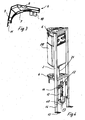
- An attachment system 1 for sanitary elements comprises a support frame, which has two vertical posts 2, which are connected to one another via a lower transverse strut 3 and an upper cross strut 4.
- the posts 2 and cross struts 3 and 4 are made of metal and can be welded together.
- On the back of the support frame two curved webs 5 are arranged at different heights, which have the shape of a semicircle.
- At the webs 5 holding means 6 are fixed, which consist of plastic and are guided there displaceable. Beneath the lower transverse strut 3, webs 12 and a lower end strip 13 are mounted between the posts 2.
- the holding means 6 comprises a curved inner surface 7 which can be applied to the web 5, wherein corresponding guide means to be present on the web 5 or the holding means 6 for a determination can.
- Distanced from the curved bar 7 straight webs 8 and 9 are provided, which are arranged at an angle of approximately 90 ° to each other. These straight webs 8 and 9 can be applied to walls of a building corner. From the webs 8 and 9 are down tabs 10 and 11 show that can be fixed to a building wall via fasteners, such as screws.
- 2 profiles 14 are inserted into the bottom side of the post, which can be telescopically clamped in the post 2, so that the posts 2 are adjustable in height.
- Bodenmann 14 plates 15 are provided on the profiles, which can be screwed to a floor.
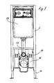
- a cistern 20 can be mounted in the upper area, which has laterally protruding tabs 23, which are screwed to the posts 2.
- the cistern 20 is followed by a drain pipe 21, which is formed bent and with an opening 22 to a basin, such as a toilet bowl, urinal can be connected.
- 12 openings 16 are recessed on the webs, can be inserted into the corresponding bolts to set a basin on the frame. Since a plurality of openings 16 are provided on the webs 12, the basin can be mounted at different heights on the webs 12. Thus, by the choice of the mounting opening 16 is a height adjustment.
- FIG. 4 shows, in the lower region of the frame 2, 3, 4, 14, a free space 40 is provided which is necessary in so-called finished floors, so that a drainage line can be warped on it in a suitcase.
- the SpülkastenMap is shaped so that a condensation protection sits by means of a pushed-down from the holder 41 positively on the hollow body.
- the cistern 20 is shown in detail.
- the cistern consisting of plastic comprises a hollow body 30, on whose front side an inspection opening 39 is formed.
- the inspection opening 39 is surrounded by a frame 33 which serves to define an actuating plate.
- the hollow body 30 is provided at the lower end with a discharge nozzle 32 which can be closed by attachable in the cistern 20 mechanisms. Laterally on the hollow body 30 protruding tabs 23 are formed to be fixed to the frame.
- the hollow body 30 with the frame 33 and the outlet pipe 32 is integrally made by injection molding.
- a lid 31 is provided in the upper region, which has a substantially triangular contour and can be latched onto the hollow body 30.
- the cistern 20 can be manufactured and installed in the simplest way.
- the connection between the cover 31 and the hollow body 30 is shown in detail in FIG FIG. 8 shown.
- the lid 31 includes a downwardly extending edge 37, on the inside protruding locking lugs 38 are formed.
- the hollow body 30, however, comprises a vertically upwardly projecting edge 34, which is provided with recesses 35, arranged above the thickened latching elements 36 are.
- the lid 31 is merely snapped onto the hollow body 30, wherein the elastic edge 37 jumps outwards until the latching noses 38 rest in the recesses 35. After the degree of filling of the cistern 20 does not rise to the lid 31, no leakage problems can arise in this area.
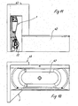
- FIGS. 9 to 12 show the installation of the fastening system 1 in combination with a bathtub 42. Thereafter, the fastening system 1 is placed laterally at the head or at the foot of a bathtub 42. In the execution of the FIG. 9 the fastening system 1 is in a formed from the side wall of the bath 42 and a transverse wall 43 thereto.
- the FIG. 10 shows the arrangement in a plan view. Thereafter, the end portion of the bathtub 42 is installed in the corner of a wall member 43. The fastening system 1 is then installed in the side wall formed by the room interior and a corner formed transversely thereto.
- the FIG. 11 shows this arrangement in a side view.
- the FIG. 12 shows that the angular wall member 43 in turn surrounds the end portion of a bathtub 42, but that the fastener 1 is laterally next to a side wall of the bathtub or at the head or foot end mutatis mutandis free in the room.
Landscapes
- Health & Medical Sciences (AREA)
- Life Sciences & Earth Sciences (AREA)
- Engineering & Computer Science (AREA)
- Hydrology & Water Resources (AREA)
- Public Health (AREA)
- Water Supply & Treatment (AREA)
- Residential Or Office Buildings (AREA)
- External Artificial Organs (AREA)
- Absorbent Articles And Supports Therefor (AREA)
- Orthopedics, Nursing, And Contraception (AREA)
- Sanitary Device For Flush Toilet (AREA)
Description
- Die vorliegende Erfindung betrifft ein Befestigungssystem für Sanitärelemente, mit einem Gestell, das bodenseitig auf mindestens einem Pfosten abgestützt ist und Befestigungsmittel für einen Spülkasten aufweist, der zwischen zwei Pfosten aufgenommen ist, wobei das Gestell für die Eckmontage geeignet ist und Haltemittel an dem Gestell für eine Wandmontage vorgesehen sind.
- Aus der
EP 0 939 170 ist ein gattungsgemäßes Befestigungssystem für die Vorwandmontage bekannt, bei dem ein Einbaurahmen an vertikalen Seitenteilen Befestigungswinkel aufweist, damit der Einbaurahmen an Wänden einer 90° Gebäudeecke montiert werden kann. An dem Einbaurahmen können dann Sanitärelemente festgelegt werden, wobei diese ebenfalls für den Einbau in eine Gebäudeecke geeignet sind. Nachteilig bei diesem Befestigungssystem ist, dass dieses sich nur starr in eine 90° Gebäudeecke montieren lässt, es aber Winkelabweichungen geben kann, die nicht ausgeglichen werden können. Zudem kann es wünschenswert sein, die Sanitärelemente nicht unter 45° von der Gebäudeecke hervorstehen zu lassen, sondern eine geringfügige Drehung aus Platzgründen vorzunehmen. Schließlich ist auch der Spülkasten für die Eckmontage aufwendig hergestellt, meist im Blasformverfahren. - Des Weiteren ist aus dem Dokument
DE-U-203 00 469 ein Verbinder für die Befestigung von Montageprofilen der Sanitärtechnik bekannt, der zwei scharnierartig miteinander verbundene Verbindungslaschen aufweist, die jeweils Mittel zu ihrer Befestigung an einem Montageprofil oder einer Gebäudewand aufweisen. Aus entsprechenden Verbindern und Hohlprofilstangen lässt sich ein Traggestell bilden, das sich insbesondere in einer Raumecke montieren lässt. Für eine individuelle Anpassung eines aus entsprechenden Verbindern und Hohlprofilstangen gebildeten Traggestells an eine Raumecke bzw. an die gewünschte Ausrichtung des daran zu montierenden Sanitärgegenstandes ist die Einstellung aller Verbinder, wobei relativ viele Verbinder zur Herstellung eines Traggestells benötigt werden, erforderlich. Der Zeitbedarf für die Montage des Traggestells und die Einstellung der Verbinder ist unbefriedigend. - Aus dem Dokument
EP-A-1 371 788 ist ein Montagegestell für Sanitärapparate bekannt, das einen Montagerahmen aufweist, der an einem unteren Ende auf einen Gebäudeboden abzustellende Füße und an einem oberen Ende verstellbare Seitenstützen zu seiner Befestigung an einer Gebäudewand aufweist. An den Seitenstützen sind Beplankungsschienen angebracht, die sich vorzugsweise parallel zu vertikalen Streben des Montagerahmens erstrecken. An den Seitenstützen sind zudem schwenkbare Wandwinkel gelagert. Das Montagegestell lässt sich in einer Raumecke montieren, wobei der Montagerahmen auch so ausgerichtet werden kann, dass das daran anzubringende Sanitärelement in einem von 45° abweichenden Winkel von den die Gebäudeecke bildenden Wänden hervorsteht. Die Montage und Ausrichtung dieses Montagegestells erfordert jedoch relativ viel Zeit. - In der
EP-A-0 201 768 ist eine WC-Installationseinheit beschrieben, die aus einem Formteil besteht, in welchem Ver- und/oder Entsorgungsleitungen, Steuerarmaturen und ein Spülkasten integriert sind. Der Hohlkörper des Spülkastens ist durch eine separat gefertigte Haube verschlossen, die eine von einem Einbaurahmen umgebende Revisionsöffnung aufweist. Die Aufhängung bzw. Ausstellung des Formteils erfolgt mittels eingeformter Schlitze, durch die die Installationseinheit auf die vorstehenden Arme eines an eine bauseitige Wand zu befestigenden Montagebügels aufschiebbar ist. Die im Wesentlichen flache Vorderwand und Rückwand der Installationseinheit sind zu seitlichen Versteifungs- bzw. Befestigungsflanschen verlängert, die im Wesentlichen deckungsgleich sind und Rechteckform aufweisen. Die Versteifungs- bzw. Befestigungsflansche definieren somit relativ breite und tiefe Vermörtelungsnuten, in die auch Blechprofile einsetzbar sind, die bei Einbau der Installationseinheit in Leichtbauwände zur Verankerung von Blechschrauben dienen und bei freier Aufstellung der Installationseinheit durch Fußstützen verlängerbar sind. - Aufgabe der vorliegenden Erfindung ist es, ein Befestigungssystem der eingangs genannten Art zu schaffen, das einfach aufgebaut ist und flexibel in Gebäudeecken montiert werden kann.
- Diese Aufgabe wird durch ein Befestigungssystem mit den Merkmalen des Anspruchs 1 gelöst.
- Erfindungsgemäß umfasst das Befestigungssystem für Sanitärelemente ein Gestell, an dem rückseitig mindestens ein gebogener Steg hervorsteht, an dem Haltemittel verschiebbar geführt sind, so dass das Gestell in unterschiedlichen Winkelpositionen relativ zu den Wänden einer Gebäudeecke montierbar ist. Dadurch muss das Gestell nicht mehr starr in einer 90° Gebäudeecke montiert werden, sondern es kann eine individuelle Anpassung vorgenommen werden, so dass die Sanitärelemente auch in abweichenden Winkeln in den Raum hervorstehen können. Ferner können Winkelunterschiede an Gebäudeecken ausgeglichen werden, da diese nicht immer im 90° Winkel vorliegen.
- Gemäß einer bevorzugten Ausgestaltung der Erfindung können die Haltemittel an dem Steg eingehängt werden und weisen hervorstehende Laschen zur Festlegung des Gestells an Wänden eines Gebäudes auf. Dadurch kann durch ein Verschieben der Haltemittel die Position des Gestells relativ zu der Gebäudeecke variiert werden. Wenn die gewünschte Position erreicht ist, kann das Haltemittel an der Gebäudewand fixiert werden, sodass das Gestell in der Position ebenfalls festgelegt ist.
- In Gebäuden werden häufig Fertigfußböden verlegt. Es ist dann notwendig, eine Entwässerungsleitung in einer Abkofferung zu verlegen. Es ist deshalb vorgesehen, dass im unteren Bereich des Gestells ein Freiraum vorgesehen ist, in dem ein Entwässerungsleitungsverzug installierbar ist. Bei der Montage ist es notwendig, dass der Bogen nach vorne herausgezogen werden kann. Damit die notwendige Stabilität erhalten bleibt, ist vorgesehen, dass im unteren Bereich des Gestells die Querverstrebung so ausgebildet ist, dass bei der Montage auf einem Fertigfußboden der Entwässerungsbogen von vorn montierbar ist. In weiterer Ausgestaltung ist noch vorgesehen, dass das Gestell mit jeweils zwei rückseitigen Haltemitteln bzw. rückseitigen Profilen ausgestattet ist, sodass eine rückseitige Verkleidung mit einer geeigneten Platte möglich ist. Diese Platte ist immer dann erforderlich, wenn das Befestigungssystem nicht in einer Raumecke platziert, sondern in einer Ecke installiert wird, die aus der Seitenwand einer Badewanne und einer quer dazu stehenden Wand gebildet ist.
- Vorzugsweise sind die Pfosten des Gestells für eine Höhenverstellung teleskopierbar ausgebildet. Denn die Montagehöhe kann somit auf einfache Weise für den jeweiligen Einsatzzweck angepasst werden. Eine weitere Möglichkeit der Höhenverstellung kann dadurch erreicht werden, dass zwischen den Pfosten Stege für Befestigungsmittel für die Montage von Becken vorgesehen sind und die Befestigungsmittel in unterschiedlichen Höhen montierbar sind. Beispielsweise können an den Stegen mehrere in der Höhe voneinander beabstandete Öffnungen vorgesehen sein, an denen dann die Gewindebolzen für die Montage der Becken eingeführt werden können.
- Vorzugsweise ist zwischen den Pfosten des Gestells ein Spülkasten mit einem Hohlkörper vorgesehen, an dessen Vorderseite eine Revisionsöffnung ausgebildet ist, die von einem Einbaurahmen umgeben ist, der integral mit dem Hohlkörper im Spritzgussverfahren hergestellt ist, wobei der Hohlkörper über einen separat ausgebildeten Deckel verschlossen ist. Dadurch entsteht der Eindruck, dass es sich um einen einteiligen nach dem Blasverfahren hergestellten Spülkasten handelt, wobei jedoch das einfachere Herstellungsverfahren genutzt wurde, wobei der zweiteilige Spülkasten aus Hohlkörper und Deckel auf einfache Weise montiert werden kann. Dabei ist der Rahmen für die Revisionsöffnung integral an dem Hohlkörper angeformt und nur die obere Öffnung durch den separat ausgebildeten Deckel verschlossen.
- Gemäß einer bevorzugten Ausführungsform ist der Deckel an dem Hohlkörper verrastbar. Dabei können an dem Hohlkörper Rastnasen angespritzt sein, die mit entsprechenden Rastelementen an dem Deckel in Eingriff bringbar sind.
- Häufig ist bei der Installation ein sogenannter Schwitzwasserschutz notwendig. Es ist deshalb vorgesehen, dass der Spülkastenkörper mittels einer von unten aufgeschobenen Halterung formschlüssig auf dem Hohlkörper aufsetzbar ist.
- Der Hohlkörper des Spülkastens weist eine für den Einbau in Gebäudeecken geeignete Kontur auf und kann beispielsweise in Draufsicht im Wesentlichen dreiecksförmig sein. Dabei kann die Kontur so bemessen sein, dass benachbart zu dem Spülkasten noch Bewässerungsleitungen zur Versorgung des Spülkastens mit Frischwasser gelegt werden können.
- Die Erfindung wird nachfolgend anhand mehrerer Ausführungsbeispiele mit Bezug auf die beigefügten Zeichnungen näher erläutert. Es zeigen:
- Figur 1
- eine perspektivische Ansicht eines erfindungsgemäßen Traggestells nach einer ersten Ausführungsform;
- Figur 2
- eine Draufsicht auf das Traggestell der
Figur 1 ; - Figur 3
- eine perspektivische Ansicht eines Haltemittels des Traggestells der
Figur 1 ; - Figur 4
- eine perspektivische Ansicht des Traggestells der
Figur 1 mit Spülkasten; - Figur 5
- eine Vorderansicht des Traggestells der
Figur 4 ; - Figur 6
- eine perspektivische rückseitige Ansicht des Traggestells der
Figur 4 ; - Figur 7
- eine perspektivische Ansicht eines Spülkastens;
- Figur 8
- eine Detailansicht des Spülkastens der
Figur 7 ; - Figur 9
- das Befestigungssystem welches in einer von einer Badewanne und einer quer dazu stehenden Wand gebildeten Ecken montiert ist;
- Figur 10
- die Anordnung gemäß der
Figur 9 in einer Draufsicht; - Figur 11
- die Anordnung gemäß den
Figuren 9 und10 in einer Seitenansicht; und - Figur 12
- eine der
Figur 11 entsprechende Darstellung, jedoch mit einem spiegelbildlich montierten Befestigungssystem. - Ein Befestigungssystem 1 für Sanitärelemente umfasst ein Traggestell, das zwei vertikale Pfosten 2 aufweist, die über eine untere Querstrebe 3 und eine obere Querstrebe 4 miteinander verbunden sind. Die Pfosten 2 und Querstreben 3 und 4 bestehen aus Metall und können miteinander verschweißt sein. Rückseitig an dem Traggestell sind zwei gebogene Stege 5 in unterschiedlicher Höhe angeordnet, die die Form eines Halbkreises besitzen. An den Stegen 5 sind Haltemittel 6 festgelegt, die aus Kunststoff bestehen und dort verschiebbar geführt sind. Unterhalb der unteren Querstrebe 3 sind Stege 12 und eine untere Abschlussleiste 13 zwischen den Pfosten 2 montiert.
- Wie in
Figur 3 zu sehen ist, umfasst das Haltemittel 6 eine gebogene Innenfläche 7, die an dem Steg 5 anlegbar ist, wobei entsprechende Führungsmittel an dem Steg 5 oder dem Haltemittel 6 für eine Festlegung vorhanden sein können. Beabstandet von der gebogenen Leiste 7 sind gerade Stege 8 und 9 vorgesehen, die in einem Winkel von etwa 90° zueinander angeordnet sind. Diese geraden Stege 8 und 9 können an Wände einer Gebäudeecke angelegt werden. Von den Stegen 8 und 9 stehen nach unten Laschen 10 und 11 hervor, die an einer Gebäudewand über Befestigungsmittel, wie Schrauben festlegbar sind. Durch ein Verschieben der Haltemittel 6 entlang des Steges 5 kann somit die Position des Gestelles variiert werden, wobei nach Ausrichtung des Gestelles eine Fixierung über die Befestigungsmittel an den Laschen 10 und 11 erfolgen kann. - Wie in den
Figuren 4 bis 6 zu sehen ist, sind in den Pfosten 2 Profile 14 bodenseitig eingeschoben, die teleskopierbar in den Pfosten 2 festgeklemmt werden können, sodass die Pfosten 2 in der Höhe verstellbar sind. Bodenseitig sind an den Profilen 14 Platten 15 vorgesehen, die an einem Boden festgeschraubt werden können. Zwischen den Pfosten 2 ist im oberen Bereich ein Spülkasten 20 montierbar, der seitlich hervorstehende Laschen 23 aufweist, die an den Pfosten 2 verschraubt sind. An den Spülkasten 20 schließt sich ein Ablaufrohr 21 an, das gebogen ausgebildet ist und mit einer Öffnung 22 an ein Becken, wie ein WC-Becken, Urinal anschließbar ist. Hierfür sind an den Stegen 12 Öffnungen 16 ausgespart, in die entsprechende Schraubbolzen eingefügt werden können, um ein Becken an dem Gestell festzulegen. Da mehrere Öffnungen 16 an den Stegen 12 vorgesehen sind, kann das Becken in unterschiedlichen Höhen an den Stegen 12 montiert werden. Somit kann durch die Wahl der Montageöffnung 16 eine Höhenverstellung erfolgen. - Wie die
Figur 4 zeigt, ist im unteren Bereich des Gestells 2, 3, 4, 14 ein Freiraum 40 vorgesehen, der bei sogenannten Fertigfußböden notwendig ist, damit eine Entwässerungsleitung darauf in einer Abkofferung verzogen werden kann. Wie dieFigur 6 zeigt, ist der Spülkastenkörper so geformt, dass ein Schwitzwasserschutz mittels einer von unten aufgeschobenen Halterung 41 formschlüssig auf dem Hohlkörper sitzt. - In
Figur 7 ist der Spülkasten 20 im Detail dargestellt. Der aus Kunststoff bestehende Spülkasten umfasst einen Hohlkörper 30, an dessen Vorderseite eine Revisionsöffnung 39 ausgebildet ist. Die Revisionsöffnung 39 ist von einem Rahmen 33 umgeben, der zur Festlegung einer Betätigungsplatte dient. Der Hohlkörper 30 ist am unteren Ende mit einem Ablaufstutzen 32 versehen, der durch in dem Spülkasten 20 montierbare Mechaniken verschließbar ist. Seitlich an dem Hohlkörper 30 sind hervorstehende Laschen 23 zur Festlegung an dem Gestell ausgebildet. Der Hohlkörper 30 mit dem Rahmen 33 und dem Ablaufstutzen 32 ist einstückig im Spritzgussverfahren hergestellt. - Um den Hohlkörper 30 zu verschließen, ist im oberen Bereich ein Deckel 31 vorgesehen, der eine im Wesentlichen dreieckförmige Kontur besitzt und auf den Hohlkörper 30 aufrastbar ist. Dadurch kann der Spülkasten 20 auf einfachste Weise hergestellt und eingebaut werden.
- Die Verbindung zwischen Deckel 31 und Hohlkörper 30 ist im Detail in
Figur 8 dargestellt. Der Deckel 31 umfasst eine sich nach unten erstreckende Kante 37, an der innen hervorstehende Rastnasen 38 ausgebildet sind. Der Hohlkörper 30 hingegen umfasst einen senkrecht nach oben hervorstehenden Rand 34, der mit Aussparungen 35 versehen ist, oberhalb der verdickte Rastelemente 36 angeordnet sind. Der Deckel 31 wird lediglich auf dem Hohlkörper 30 aufgerastet, wobei der elastische Rand 37 nach außen springt, bis die Rastnasen 38 in den Aussparungen 35 anliegen. Nachdem der Füllungsgrad des Spülkastens 20 nicht bis zu dem Deckel 31 steigt, können sich in diesem Bereich auch keine Dichtigkeitsprobleme ergeben. - Die
Figuren 9 bis 12 zeigen die Aufstellung des Befestigungssystems 1 in Kombination mit einer Badewanne 42. Danach wird das Befestigungssystem 1 seitlich an das Kopf- oder an das Fußende einer Badewanne 42 aufgestellt. Bei der Ausführung nach derFigur 9 steht das Befestigungssystem 1 in einer aus der Seitenwand der Badewanne 42 und einer quer dazu stehenden Wand 43 gebildeten Ecke. DieFigur 10 zeigt die Anordnung in einer Draufsicht. Danach wird der Endbereich der Badewanne 42 in die Ecke eines Wandelementes 43 installiert. Das Befestigungssystem 1 ist dann in der aus der zum Rauminneren liegenden Seitenwand und einer quer dazu verlaufenden Wand gebildeten Ecke installiert. DieFigur 11 zeigt diese Anordnung in einer Seitenansicht. DieFigur 12 zeigt, dass das winkelförmige Wandelement 43 wiederum den Endbereich einer Badewanne 42 umgreift, dass jedoch das Befestigungselement 1 seitlich neben einer Seitenwand der Badewanne oder an dem Kopf oder Fußende sinngemäß frei im Raum steht. - Die Ausführungen sind beispielhaft zu sehen. Wesentlich ist, dass es nicht zwingend notwendig ist, dass das Befestigungssystem 1 in einer aus zwei rechtwinklig zueinanderstehenden Wänden gebildeten Ecke installiert ist.
Claims (13)
- Befestigungssystem für Sanitärelemente, mit einem Gestell (2, 3, 4, 14), das bodenseitig auf mindestens einem Pfosten (2, 14) abgestützt ist und Befestigungsmittel für einen Spülkasten (20) aufweist, der zwischen zwei Pfosten (2, 14) aufgenommen ist, wobei das Gestell (2, 3, 4, 14) für die Eckmontage geeignet ist und Haltemittel (6, 10, 11, 10', 11') an dem Gestell (2, 3, 4, 14) für eine Wandmontage vorgesehen sind,
dadurch gekennzeichnet, dass an dem Gestell (2, 3, 4, 14) rückseitig mindestens ein gebogener Steg (5) hervorsteht, an dem die Haltemittel (6) verschiebbar geführt sind, so dass das Gestell (2, 3, 4, 14) in unterschiedlichen Winkelpositionen relativ zu den Wänden einer Gebäudeecke montierbar ist. - Befestigungssystem nach Anspruch 1,
dadurch gekennzeichnet, dass die Haltemittel (6) an dem Steg (5) einhängbar sind und hervorstehende Laschen (10, 11) zur Festlegung des Gestells (2, 3, 4, 14) an Wänden eines Gebäudes aufweisen. - Befestigungssystem nach Anspruch 1 oder 2,
dadurch gekennzeichnet, dass die Pfosten (2, 14) des Gestells für eine Höhenverstellung teleskopierbar ausgebildet sind. - Befestigungssystem nach einem der Ansprüche 1 bis 3,
dadurch gekennzeichnet, dass zwischen den Pfosten (2) Stege (12) für Befestigungsmittel für die Montage von Becken vorgesehen sind und die Befestigungsmittel in unterschiedlichen Höhen montierbar sind. - Befestigungssystem nach einem der Ansprüche 1 bis 4,
dadurch gekennzeichnet, dass das Gestell (2, 3, 4, 14) im unteren Bereich einen Freiraum (40) zur Aufnahme eines Entwässerungsleitungsverzuges aufweist. - Befestigungssystem nach einem der Ansprüche 1 bis 5,
dadurch gekennzeichnet, dass im unteren Bereich des Gestells (2, 3, 4, 14) eine Querverstrebung (13) derart ausgebildet ist, dass ein Entwässerungsbogen von vorn montierbar ist. - Befestigungssystem nach einem der Ansprüche 1 bis 6,
dadurch gekennzeichnet, dass das Gestell (2, 3, 4, 14) mit jeweils zwei rückseitigen Haltemitteln (6) ausgestattet ist, sodass das Befestigungssystem rückseitig mit einer Platte verkleidbar ist. - Befestigungssystem nach einem der Ansprüche 1 bis 7,
dadurch gekennzeichnet, dass zwischen den Pfosten (2, 14) ein Spülkasten (20) mit einem Hohlkörper (30) vorgesehen ist, an dessen Vorderseite eine Revisionsöffnung (39) ausgebildet ist, die von einem Einbaurahmen (33) umgeben ist, der integral mit dem Hohlkörper (30) im Spritzgussverfahren hergestellt ist, wobei der Hohlkörper (30) über einen separat ausgebildeten Deckel (31) verschlossen ist. - Befestigungssystem nach Anspruch 8,
dadurch gekennzeichnet, dass der Deckel (31) an dem Hohlkörper (30) verrastbar ist. - Befestigungssystem nach Anspruch 9,
dadurch gekennzeichnet, dass an dem Hohlkörper (30) Rastnasen (36) angespritzt sind, die mit entsprechenden Rastelementen (38) an dem Deckel (31) in Eingriff bringbar sind. - Befestigungssystem nach einem der Ansprüche 8 bis 10,
dadurch gekennzeichnet, dass der Hohlkörper (30) in Draufsicht im Wesentlichen dreiecksförmig ist. - Befestigungssystem nach einem der Ansprüche 8 bis 11,
dadurch gekennzeichnet, dass an dem Hohlkörper (30) seitlich hervorstehende Laschen (23) zur Festlegung an dem Gestell (2, 3, 4, 14) ausgebildet sind. - Befestigungssystem nach einem der Ansprüche 8 bis 12,
dadurch gekennzeichnet, dass der Spülkastenkörper derart geformt ist, dass ein Schwitzwasserschutz mittels einer von unten aufgeschobenen Halterung (41) formschlüssig auf dem Hohlkörper aufsetzbar ist.
Applications Claiming Priority (2)
| Application Number | Priority Date | Filing Date | Title |
|---|---|---|---|
| DE202005003864 | 2005-03-08 | ||
| DE202005016946U DE202005016946U1 (de) | 2005-03-08 | 2005-10-27 | Befestigungssystem für Sanitärelemente und Spülkasten |
Publications (3)
| Publication Number | Publication Date |
|---|---|
| EP1700960A2 EP1700960A2 (de) | 2006-09-13 |
| EP1700960A3 EP1700960A3 (de) | 2008-08-27 |
| EP1700960B1 true EP1700960B1 (de) | 2010-06-09 |
Family
ID=35669072
Family Applications (1)
| Application Number | Title | Priority Date | Filing Date |
|---|---|---|---|
| EP06004705A Expired - Lifetime EP1700960B1 (de) | 2005-03-08 | 2006-03-08 | Befestigungssystem für Sanitärelemente und Spülkasten |
Country Status (4)
| Country | Link |
|---|---|
| EP (1) | EP1700960B1 (de) |
| AT (1) | ATE470763T1 (de) |
| DE (2) | DE202005016946U1 (de) |
| ES (1) | ES2344797T3 (de) |
Families Citing this family (5)
| Publication number | Priority date | Publication date | Assignee | Title |
|---|---|---|---|---|
| DE202006016840U1 (de) * | 2006-10-31 | 2008-03-06 | Comfort Sinusverteiler Gmbh | Kaskadeneinheit für eine Heizungsanlage |
| NL2004067C2 (nl) * | 2010-01-06 | 2011-07-07 | Easy Sanitary Solutions B V | Inbouwreservoir. |
| ES2605202B1 (es) * | 2015-09-10 | 2017-10-04 | Juan Pedro Burgos Castillo | Cisterna monobloque |
| CN214657490U (zh) * | 2021-01-20 | 2021-11-09 | 厦门融技精密科技有限公司 | 一种能够加长调节范围的固定机构 |
| DE202021106653U1 (de) | 2021-12-07 | 2023-03-08 | Viega Technology Gmbh & Co. Kg | Halterung für einen Vorwand-Montagerahmen sowie Befestigungssystem mit einer solchen Halterung und einem Vorwand-Montagerahmen |
Family Cites Families (9)
| Publication number | Priority date | Publication date | Assignee | Title |
|---|---|---|---|---|
| US2652875A (en) * | 1951-02-26 | 1953-09-22 | Puste Elizabeth | Cover for toilet tanks |
| US3760428A (en) * | 1971-10-29 | 1973-09-25 | Borg Warner | Water closet tank |
| DE3517907A1 (de) * | 1985-05-17 | 1986-11-20 | Sanbloc GmbH Installations-Fertigbau, 8120 Weilheim | Wc-installationseinheit |
| AU673292B2 (en) * | 1993-11-10 | 1996-10-31 | Caroma Industries Limited | A cistern |
| DE19636298C1 (de) * | 1996-09-06 | 1997-12-18 | Rost & Co Gmbh | Spülkasten |
| DE29621470U1 (de) * | 1996-12-11 | 1997-06-12 | Rohmann, Klaus, 44357 Dortmund | Spülkasten für ein Wasserklosett, ein Urinal o.dgl. |
| DE29803394U1 (de) | 1998-02-26 | 1998-05-14 | E. Missel GmbH & Co., 70374 Stuttgart | Spülsystem |
| ATE374871T1 (de) * | 2002-06-10 | 2007-10-15 | Geberit Technik Ag | Montagegestell für sanitärapparate |
| DE20300469U1 (de) * | 2003-01-14 | 2003-06-12 | Geberit Technik AG, Jona, St. Gallen | Verbinder für die Befestigung von Montageprofilen der Sanitärtechnik sowie Traggestell mit einem solchen Verbinder |
-
2005
- 2005-10-27 DE DE202005016946U patent/DE202005016946U1/de not_active Expired - Lifetime
-
2006
- 2006-03-08 AT AT06004705T patent/ATE470763T1/de active
- 2006-03-08 DE DE502006007136T patent/DE502006007136D1/de not_active Expired - Lifetime
- 2006-03-08 EP EP06004705A patent/EP1700960B1/de not_active Expired - Lifetime
- 2006-03-08 ES ES06004705T patent/ES2344797T3/es not_active Expired - Lifetime
Also Published As
| Publication number | Publication date |
|---|---|
| DE502006007136D1 (de) | 2010-07-22 |
| EP1700960A2 (de) | 2006-09-13 |
| EP1700960A3 (de) | 2008-08-27 |
| ES2344797T3 (es) | 2010-09-07 |
| ATE470763T1 (de) | 2010-06-15 |
| DE202005016946U1 (de) | 2006-01-12 |
Similar Documents
| Publication | Publication Date | Title |
|---|---|---|
| EP2236683B1 (de) | Duschrinnenanordnung für Wandeinbau | |
| EP2333174B1 (de) | Duschablaufsystem | |
| EP0939170B1 (de) | Spülsystem | |
| EP1700960B1 (de) | Befestigungssystem für Sanitärelemente und Spülkasten | |
| EP0044055B1 (de) | Sanitärzelle aus vorgefertigten Bauelementen | |
| DE2902967A1 (de) | Wandelement mit verrohrung fuer nassraum, sanitaerraum, kueche o.dgl. | |
| EP0731223B1 (de) | Montagevorrichtung zur tragenden Befestigung einer Sanitäreinrichtung | |
| DE19710647A1 (de) | Waschbeckeninstallation | |
| EP2182140A1 (de) | Bausatz für eine Sanitärzelle und Sanitärzelle hergestellt aus einem solchen Bausatz | |
| EP0731226B1 (de) | Vorwandelement für die Sanitärinstallation | |
| EP0324169B1 (de) | Installationsblock | |
| AT14857U1 (de) | Einrichtung für die Körperpflege | |
| DE10207067A1 (de) | Bausatz zur Erzeugung insbesondere einer Vorwand-Eckinstallation für ein WC oder dgl. | |
| EP2690229B1 (de) | Montageeinrichtung für eine sanitäre Apparatur | |
| DE29806398U1 (de) | Spülsystem | |
| EP0790359B1 (de) | Befestigungsvorrichtung für ein Sanitärelement | |
| DE202015001752U1 (de) | Spüleinheit | |
| DE19736341C2 (de) | Befestigungsvorrichtung | |
| DE29606529U1 (de) | Sanitärgegenstand | |
| EP0520269B1 (de) | Installationsblock | |
| AT527672B1 (de) | Halteanordnung zur Verwendung in einer Vorwandinstallation | |
| EP0482506A1 (de) | Installationssystem | |
| DE29803396U1 (de) | Montagerahmen zur Positionierung und schallentkoppelten Befestigung eines Behältnisses zur Zwischenspeicherung einer vorgebbaren Wassermenge | |
| EP1367187A2 (de) | Bausatz für einen wassergespülten Sanitärgegenstand | |
| DE19756149A1 (de) | Unterputz-Eckspülkasten für Wand-WC mit und ohne Träger oder als Block bzw. Baustein |
Legal Events
| Date | Code | Title | Description |
|---|---|---|---|
| PUAI | Public reference made under article 153(3) epc to a published international application that has entered the european phase |
Free format text: ORIGINAL CODE: 0009012 |
|
| AK | Designated contracting states |
Kind code of ref document: A2 Designated state(s): AT BE BG CH CY CZ DE DK EE ES FI FR GB GR HU IE IS IT LI LT LU LV MC NL PL PT RO SE SI SK TR |
|
| AX | Request for extension of the european patent |
Extension state: AL BA HR MK YU |
|
| PUAL | Search report despatched |
Free format text: ORIGINAL CODE: 0009013 |
|
| AK | Designated contracting states |
Kind code of ref document: A3 Designated state(s): AT BE BG CH CY CZ DE DK EE ES FI FR GB GR HU IE IS IT LI LT LU LV MC NL PL PT RO SE SI SK TR |
|
| AX | Request for extension of the european patent |
Extension state: AL BA HR MK YU |
|
| 17P | Request for examination filed |
Effective date: 20090122 |
|
| 17Q | First examination report despatched |
Effective date: 20090227 |
|
| AKX | Designation fees paid |
Designated state(s): AT BE BG CH CY CZ DE DK EE ES FI FR GB GR HU IE IS IT LI LT LU LV MC NL PL PT RO SE SI SK TR |
|
| GRAP | Despatch of communication of intention to grant a patent |
Free format text: ORIGINAL CODE: EPIDOSNIGR1 |
|
| GRAS | Grant fee paid |
Free format text: ORIGINAL CODE: EPIDOSNIGR3 |
|
| GRAA | (expected) grant |
Free format text: ORIGINAL CODE: 0009210 |
|
| AK | Designated contracting states |
Kind code of ref document: B1 Designated state(s): AT BE BG CH CY CZ DE DK EE ES FI FR GB GR HU IE IS IT LI LT LU LV MC NL PL PT RO SE SI SK TR |
|
| REG | Reference to a national code |
Ref country code: CH Ref legal event code: EP |
|
| REG | Reference to a national code |
Ref country code: CH Ref legal event code: NV Representative=s name: TROESCH SCHEIDEGGER WERNER AG |
|
| REG | Reference to a national code |
Ref country code: IE Ref legal event code: FG4D Free format text: LANGUAGE OF EP DOCUMENT: GERMAN |
|
| REF | Corresponds to: |
Ref document number: 502006007136 Country of ref document: DE Date of ref document: 20100722 Kind code of ref document: P |
|
| REG | Reference to a national code |
Ref country code: NL Ref legal event code: T3 |
|
| REG | Reference to a national code |
Ref country code: ES Ref legal event code: FG2A Ref document number: 2344797 Country of ref document: ES Kind code of ref document: T3 |
|
| PG25 | Lapsed in a contracting state [announced via postgrant information from national office to epo] |
Ref country code: SE Free format text: LAPSE BECAUSE OF FAILURE TO SUBMIT A TRANSLATION OF THE DESCRIPTION OR TO PAY THE FEE WITHIN THE PRESCRIBED TIME-LIMIT Effective date: 20100609 Ref country code: LT Free format text: LAPSE BECAUSE OF FAILURE TO SUBMIT A TRANSLATION OF THE DESCRIPTION OR TO PAY THE FEE WITHIN THE PRESCRIBED TIME-LIMIT Effective date: 20100609 |
|
| LTIE | Lt: invalidation of european patent or patent extension |
Effective date: 20100609 |
|
| PG25 | Lapsed in a contracting state [announced via postgrant information from national office to epo] |
Ref country code: SI Free format text: LAPSE BECAUSE OF FAILURE TO SUBMIT A TRANSLATION OF THE DESCRIPTION OR TO PAY THE FEE WITHIN THE PRESCRIBED TIME-LIMIT Effective date: 20100609 Ref country code: LV Free format text: LAPSE BECAUSE OF FAILURE TO SUBMIT A TRANSLATION OF THE DESCRIPTION OR TO PAY THE FEE WITHIN THE PRESCRIBED TIME-LIMIT Effective date: 20100609 Ref country code: FI Free format text: LAPSE BECAUSE OF FAILURE TO SUBMIT A TRANSLATION OF THE DESCRIPTION OR TO PAY THE FEE WITHIN THE PRESCRIBED TIME-LIMIT Effective date: 20100609 |
|
| PG25 | Lapsed in a contracting state [announced via postgrant information from national office to epo] |
Ref country code: PL Free format text: LAPSE BECAUSE OF FAILURE TO SUBMIT A TRANSLATION OF THE DESCRIPTION OR TO PAY THE FEE WITHIN THE PRESCRIBED TIME-LIMIT Effective date: 20100609 Ref country code: GR Free format text: LAPSE BECAUSE OF FAILURE TO SUBMIT A TRANSLATION OF THE DESCRIPTION OR TO PAY THE FEE WITHIN THE PRESCRIBED TIME-LIMIT Effective date: 20100910 Ref country code: CY Free format text: LAPSE BECAUSE OF FAILURE TO SUBMIT A TRANSLATION OF THE DESCRIPTION OR TO PAY THE FEE WITHIN THE PRESCRIBED TIME-LIMIT Effective date: 20100609 |
|
| REG | Reference to a national code |
Ref country code: IE Ref legal event code: FD4D |
|
| PG25 | Lapsed in a contracting state [announced via postgrant information from national office to epo] |
Ref country code: IE Free format text: LAPSE BECAUSE OF FAILURE TO SUBMIT A TRANSLATION OF THE DESCRIPTION OR TO PAY THE FEE WITHIN THE PRESCRIBED TIME-LIMIT Effective date: 20100609 Ref country code: EE Free format text: LAPSE BECAUSE OF FAILURE TO SUBMIT A TRANSLATION OF THE DESCRIPTION OR TO PAY THE FEE WITHIN THE PRESCRIBED TIME-LIMIT Effective date: 20100609 |
|
| PG25 | Lapsed in a contracting state [announced via postgrant information from national office to epo] |
Ref country code: SK Free format text: LAPSE BECAUSE OF FAILURE TO SUBMIT A TRANSLATION OF THE DESCRIPTION OR TO PAY THE FEE WITHIN THE PRESCRIBED TIME-LIMIT Effective date: 20100609 Ref country code: IS Free format text: LAPSE BECAUSE OF FAILURE TO SUBMIT A TRANSLATION OF THE DESCRIPTION OR TO PAY THE FEE WITHIN THE PRESCRIBED TIME-LIMIT Effective date: 20101009 Ref country code: RO Free format text: LAPSE BECAUSE OF FAILURE TO SUBMIT A TRANSLATION OF THE DESCRIPTION OR TO PAY THE FEE WITHIN THE PRESCRIBED TIME-LIMIT Effective date: 20100609 Ref country code: PT Free format text: LAPSE BECAUSE OF FAILURE TO SUBMIT A TRANSLATION OF THE DESCRIPTION OR TO PAY THE FEE WITHIN THE PRESCRIBED TIME-LIMIT Effective date: 20101011 |
|
| PLBE | No opposition filed within time limit |
Free format text: ORIGINAL CODE: 0009261 |
|
| STAA | Information on the status of an ep patent application or granted ep patent |
Free format text: STATUS: NO OPPOSITION FILED WITHIN TIME LIMIT |
|
| PG25 | Lapsed in a contracting state [announced via postgrant information from national office to epo] |
Ref country code: DK Free format text: LAPSE BECAUSE OF FAILURE TO SUBMIT A TRANSLATION OF THE DESCRIPTION OR TO PAY THE FEE WITHIN THE PRESCRIBED TIME-LIMIT Effective date: 20100609 |
|
| 26N | No opposition filed |
Effective date: 20110310 |
|
| REG | Reference to a national code |
Ref country code: DE Ref legal event code: R097 Ref document number: 502006007136 Country of ref document: DE Effective date: 20110309 |
|
| PG25 | Lapsed in a contracting state [announced via postgrant information from national office to epo] |
Ref country code: MC Free format text: LAPSE BECAUSE OF NON-PAYMENT OF DUE FEES Effective date: 20110331 |
|
| REG | Reference to a national code |
Ref country code: DE Ref legal event code: R083 Ref document number: 502006007136 Country of ref document: DE |
|
| PG25 | Lapsed in a contracting state [announced via postgrant information from national office to epo] |
Ref country code: TR Free format text: LAPSE BECAUSE OF FAILURE TO SUBMIT A TRANSLATION OF THE DESCRIPTION OR TO PAY THE FEE WITHIN THE PRESCRIBED TIME-LIMIT Effective date: 20100609 Ref country code: BG Free format text: LAPSE BECAUSE OF FAILURE TO SUBMIT A TRANSLATION OF THE DESCRIPTION OR TO PAY THE FEE WITHIN THE PRESCRIBED TIME-LIMIT Effective date: 20100909 |
|
| PG25 | Lapsed in a contracting state [announced via postgrant information from national office to epo] |
Ref country code: HU Free format text: LAPSE BECAUSE OF FAILURE TO SUBMIT A TRANSLATION OF THE DESCRIPTION OR TO PAY THE FEE WITHIN THE PRESCRIBED TIME-LIMIT Effective date: 20100609 |
|
| REG | Reference to a national code |
Ref country code: FR Ref legal event code: PLFP Year of fee payment: 11 |
|
| PG25 | Lapsed in a contracting state [announced via postgrant information from national office to epo] |
Ref country code: IT Free format text: LAPSE BECAUSE OF NON-PAYMENT OF DUE FEES Effective date: 20160308 |
|
| REG | Reference to a national code |
Ref country code: FR Ref legal event code: PLFP Year of fee payment: 12 |
|
| REG | Reference to a national code |
Ref country code: DE Ref legal event code: R082 Ref document number: 502006007136 Country of ref document: DE Representative=s name: COHAUSZ & FLORACK PATENT- UND RECHTSANWAELTE P, DE Ref country code: DE Ref legal event code: R081 Ref document number: 502006007136 Country of ref document: DE Owner name: VIEGA TECHNOLOGY GMBH & CO. KG, DE Free format text: FORMER OWNER: VIEGA GMBH & CO. KG, 57439 ATTENDORN, DE |
|
| REG | Reference to a national code |
Ref country code: AT Ref legal event code: PC Ref document number: 470763 Country of ref document: AT Kind code of ref document: T Owner name: VIEGA TECHNOLOGY GMBH & CO. KG, DE Effective date: 20170512 |
|
| REG | Reference to a national code |
Ref country code: LU Ref legal event code: PD Owner name: VIEGA TECHNOLOGY GMBH & CO. KG; DE Free format text: FORMER OWNER: VIEGA GMBH & CO. KG Effective date: 20170322 |
|
| REG | Reference to a national code |
Ref country code: NL Ref legal event code: PD Owner name: VIEGA TECHNOLOGY GMBH & CO. KG; DE Free format text: DETAILS ASSIGNMENT: CHANGE OF OWNER(S), ASSIGNMENT; FORMER OWNER NAME: VIEGA GMBH & CO. KG Effective date: 20170412 |
|
| REG | Reference to a national code |
Ref country code: GB Ref legal event code: 732E Free format text: REGISTERED BETWEEN 20170706 AND 20170715 |
|
| PG25 | Lapsed in a contracting state [announced via postgrant information from national office to epo] |
Ref country code: IT Free format text: LAPSE BECAUSE OF NON-PAYMENT OF DUE FEES Effective date: 20160308 |
|
| PGRI | Patent reinstated in contracting state [announced from national office to epo] |
Ref country code: IT Effective date: 20170710 |
|
| REG | Reference to a national code |
Ref country code: FR Ref legal event code: TP Owner name: VIEGA TECHNOLOGY GMBH & CO. KG, DE Effective date: 20171013 |
|
| REG | Reference to a national code |
Ref country code: ES Ref legal event code: PC2A Owner name: VIEGA TECHNOLOGY GMBH & CO. KG Effective date: 20180108 |
|
| REG | Reference to a national code |
Ref country code: CH Ref legal event code: PUE Owner name: VIEGA TECHNOLOGY GMBH AND CO. KG, DE Free format text: FORMER OWNER: VIEGA GMBH AND CO. KG, DE |
|
| REG | Reference to a national code |
Ref country code: FR Ref legal event code: PLFP Year of fee payment: 13 |
|
| PGFP | Annual fee paid to national office [announced via postgrant information from national office to epo] |
Ref country code: LU Payment date: 20210318 Year of fee payment: 16 |
|
| PGFP | Annual fee paid to national office [announced via postgrant information from national office to epo] |
Ref country code: AT Payment date: 20220322 Year of fee payment: 17 |
|
| PGFP | Annual fee paid to national office [announced via postgrant information from national office to epo] |
Ref country code: NL Payment date: 20220323 Year of fee payment: 17 Ref country code: CZ Payment date: 20220217 Year of fee payment: 17 Ref country code: BE Payment date: 20220323 Year of fee payment: 17 |
|
| PGFP | Annual fee paid to national office [announced via postgrant information from national office to epo] |
Ref country code: IT Payment date: 20220324 Year of fee payment: 17 Ref country code: ES Payment date: 20220420 Year of fee payment: 17 |
|
| PG25 | Lapsed in a contracting state [announced via postgrant information from national office to epo] |
Ref country code: LU Free format text: LAPSE BECAUSE OF NON-PAYMENT OF DUE FEES Effective date: 20220308 |
|
| PGFP | Annual fee paid to national office [announced via postgrant information from national office to epo] |
Ref country code: FR Payment date: 20230323 Year of fee payment: 18 |
|
| PGFP | Annual fee paid to national office [announced via postgrant information from national office to epo] |
Ref country code: GB Payment date: 20230322 Year of fee payment: 18 |
|
| PGFP | Annual fee paid to national office [announced via postgrant information from national office to epo] |
Ref country code: CH Payment date: 20230401 Year of fee payment: 18 |
|
| PG25 | Lapsed in a contracting state [announced via postgrant information from national office to epo] |
Ref country code: CZ Free format text: LAPSE BECAUSE OF NON-PAYMENT OF DUE FEES Effective date: 20230308 |
|
| REG | Reference to a national code |
Ref country code: NL Ref legal event code: MM Effective date: 20230401 |
|
| REG | Reference to a national code |
Ref country code: AT Ref legal event code: MM01 Ref document number: 470763 Country of ref document: AT Kind code of ref document: T Effective date: 20230308 |
|
| REG | Reference to a national code |
Ref country code: BE Ref legal event code: MM Effective date: 20230331 |
|
| PG25 | Lapsed in a contracting state [announced via postgrant information from national office to epo] |
Ref country code: NL Free format text: LAPSE BECAUSE OF NON-PAYMENT OF DUE FEES Effective date: 20230401 |
|
| PG25 | Lapsed in a contracting state [announced via postgrant information from national office to epo] |
Ref country code: AT Free format text: LAPSE BECAUSE OF NON-PAYMENT OF DUE FEES Effective date: 20230308 |
|
| PG25 | Lapsed in a contracting state [announced via postgrant information from national office to epo] |
Ref country code: BE Free format text: LAPSE BECAUSE OF NON-PAYMENT OF DUE FEES Effective date: 20230331 |
|
| PG25 | Lapsed in a contracting state [announced via postgrant information from national office to epo] |
Ref country code: ES Free format text: LAPSE BECAUSE OF NON-PAYMENT OF DUE FEES Effective date: 20230309 |
|
| REG | Reference to a national code |
Ref country code: ES Ref legal event code: FD2A Effective date: 20240426 |
|
| PG25 | Lapsed in a contracting state [announced via postgrant information from national office to epo] |
Ref country code: ES Free format text: LAPSE BECAUSE OF NON-PAYMENT OF DUE FEES Effective date: 20230309 |
|
| PGFP | Annual fee paid to national office [announced via postgrant information from national office to epo] |
Ref country code: DE Payment date: 20240321 Year of fee payment: 19 |
|
| REG | Reference to a national code |
Ref country code: CH Ref legal event code: PL |
|
| GBPC | Gb: european patent ceased through non-payment of renewal fee |
Effective date: 20240308 |
|
| PG25 | Lapsed in a contracting state [announced via postgrant information from national office to epo] |
Ref country code: GB Free format text: LAPSE BECAUSE OF NON-PAYMENT OF DUE FEES Effective date: 20240308 |
|
| PG25 | Lapsed in a contracting state [announced via postgrant information from national office to epo] |
Ref country code: FR Free format text: LAPSE BECAUSE OF NON-PAYMENT OF DUE FEES Effective date: 20240331 |
|
| PG25 | Lapsed in a contracting state [announced via postgrant information from national office to epo] |
Ref country code: GB Free format text: LAPSE BECAUSE OF NON-PAYMENT OF DUE FEES Effective date: 20240308 Ref country code: FR Free format text: LAPSE BECAUSE OF NON-PAYMENT OF DUE FEES Effective date: 20240331 Ref country code: CH Free format text: LAPSE BECAUSE OF NON-PAYMENT OF DUE FEES Effective date: 20240331 |
|
| PG25 | Lapsed in a contracting state [announced via postgrant information from national office to epo] |
Ref country code: IT Free format text: LAPSE BECAUSE OF NON-PAYMENT OF DUE FEES Effective date: 20230308 |
|
| REG | Reference to a national code |
Ref country code: DE Ref legal event code: R119 Ref document number: 502006007136 Country of ref document: DE |
|
| PG25 | Lapsed in a contracting state [announced via postgrant information from national office to epo] |
Ref country code: DE Free format text: LAPSE BECAUSE OF NON-PAYMENT OF DUE FEES Effective date: 20251001 |