EP1700971A2 - Corps profilé décoratif avec fonction d'étanchéité - Google Patents
Corps profilé décoratif avec fonction d'étanchéité Download PDFInfo
- Publication number
- EP1700971A2 EP1700971A2 EP06004935A EP06004935A EP1700971A2 EP 1700971 A2 EP1700971 A2 EP 1700971A2 EP 06004935 A EP06004935 A EP 06004935A EP 06004935 A EP06004935 A EP 06004935A EP 1700971 A2 EP1700971 A2 EP 1700971A2
- Authority
- EP
- European Patent Office
- Prior art keywords
- decorative
- profile body
- sealing
- section
- decorative element
- Prior art date
- Legal status (The legal status is an assumption and is not a legal conclusion. Google has not performed a legal analysis and makes no representation as to the accuracy of the status listed.)
- Withdrawn
Links
- 238000007789 sealing Methods 0.000 title claims description 66
- 230000009975 flexible effect Effects 0.000 claims abstract description 10
- 239000000463 material Substances 0.000 claims description 9
- 239000011888 foil Substances 0.000 abstract description 2
- 238000005034 decoration Methods 0.000 abstract 1
- 230000007704 transition Effects 0.000 description 11
- 230000000694 effects Effects 0.000 description 2
- 239000010408 film Substances 0.000 description 2
- 230000001154 acute effect Effects 0.000 description 1
- 239000000853 adhesive Substances 0.000 description 1
- 230000001070 adhesive effect Effects 0.000 description 1
- 238000001125 extrusion Methods 0.000 description 1
- 238000009434 installation Methods 0.000 description 1
- 238000004519 manufacturing process Methods 0.000 description 1
- 238000000034 method Methods 0.000 description 1
- 230000003287 optical effect Effects 0.000 description 1
- 239000007858 starting material Substances 0.000 description 1
- 239000010409 thin film Substances 0.000 description 1
Images


Classifications
-
- E—FIXED CONSTRUCTIONS
- E04—BUILDING
- E04F—FINISHING WORK ON BUILDINGS, e.g. STAIRS, FLOORS
- E04F19/00—Other details of constructional parts for finishing work on buildings
- E04F19/02—Borders; Finishing strips, e.g. beadings; Light coves
- E04F19/04—Borders; Finishing strips, e.g. beadings; Light coves for use between floor or ceiling and wall, e.g. skirtings
- E04F19/045—Hygienic or watertight plinths
-
- E—FIXED CONSTRUCTIONS
- E04—BUILDING
- E04F—FINISHING WORK ON BUILDINGS, e.g. STAIRS, FLOORS
- E04F19/00—Other details of constructional parts for finishing work on buildings
- E04F19/02—Borders; Finishing strips, e.g. beadings; Light coves
- E04F19/04—Borders; Finishing strips, e.g. beadings; Light coves for use between floor or ceiling and wall, e.g. skirtings
- E04F2019/0404—Borders; Finishing strips, e.g. beadings; Light coves for use between floor or ceiling and wall, e.g. skirtings characterised by the material
- E04F2019/0413—Borders; Finishing strips, e.g. beadings; Light coves for use between floor or ceiling and wall, e.g. skirtings characterised by the material of metal
-
- E—FIXED CONSTRUCTIONS
- E04—BUILDING
- E04F—FINISHING WORK ON BUILDINGS, e.g. STAIRS, FLOORS
- E04F19/00—Other details of constructional parts for finishing work on buildings
- E04F19/02—Borders; Finishing strips, e.g. beadings; Light coves
- E04F19/04—Borders; Finishing strips, e.g. beadings; Light coves for use between floor or ceiling and wall, e.g. skirtings
- E04F2019/0454—Borders; Finishing strips, e.g. beadings; Light coves for use between floor or ceiling and wall, e.g. skirtings with decorative effects
Definitions
- the invention relates to a decorative profile body with sealing function, preferably for a wall connection profile, with at least one support portion, at least one adjacent the support portion sealing portion and the support portion at least partially covering decorative element.
- a generic decorative profile body is for example from the DE 199 46 617 A1 known.
- the decorative profile comprises a carrier made of plastic and a decorative layer, wherein the decorative layer is arranged with its rear side on the visible side of the carrier and is connected to the carrier surface with an adhesive.
- Such a decorative profile is used for example as a wall connection profile in the transition region between a kitchen worktop and an adjacent wall.
- the longitudinal edge sealing lips When installing the conventional, generic sealing profile body at a destination, the longitudinal edge sealing lips must be brought under pressure into contact with the surfaces to be sealed, so that the sealing lips protrude to the visible side over the visible surface of the decorative profile, which is often perceived as disturbing in optical and aesthetic terms , Often, the sealing lips are also colored by both the adjacent and sealed surfaces and the rest of the structure of the sealing profile.
- the invention has for its object to improve the known from the prior art decorative profile body to the effect that just in the installed state creates a pleasing aesthetic and aesthetic overall impression. This is achieved by the characterizing features of claim 1 according to the invention. Further advantageous embodiments are described in the subclaims.
- the decorative profile body according to the invention of the aforementioned type is characterized in that the decorative element is flexible and at least partially overlaps the sealing portion.
- the decorative profile body In the installed state of the decorative profile body follows the flexible decorative element of the deformation of the sealing portion, so that just the transition region between the support portion and the sealing portion from the visible side is not visible.
- the decorative profile body according to the invention in the installed state produces a significantly improved overall impression compared with the prior art.
- the decorative element substantially completely overlaps the sealing section on the visible side. As a result, between the adjacent surfaces to be sealed and the decorative profile body a flowing, almost invisible transition can be accomplished.
- the decorative profile body has two sealing sections.
- the decorative profile body of this type is particularly suitable for a wall connection profile, which is arranged in the transition region of a kitchen worktop and an adjacent wall.
- the shape of the decorative element is designed to be particularly simple when the decorative element has at least partially plastic.
- Plastic as a starting material is particularly suitable for giving the decorative element its flexible properties.
- the manufacturing process of the decorative profile body according to the invention is particularly simple if the decorative element is a film.
- the foil may e.g. be unwound from a supply roll and connected to an extrusion profile forming the carrier body.
- a particularly shapely surface on the visible side of the Dekarprofil stressess can be accomplished that the decorative element is materially connected to the support portion and / or the sealing portion.
- the decorative element can be embedded in the material of the decorative profile body particularly cleanly and without disturbing gaps if the surface of the decorative element extends approximately in alignment with a surface section of the sealing section.
- a smooth transition can be accomplished especially on the visible side, in the transition region between the decorative profile body and a surface to be sealed.
- a particularly shapely surface structure can be achieved if the decorative element has a softer material than the carrier section.
- the softer decorative element may have any imperfections, e.g. Edge or the like, compensate for the surface of the support portion and prevent these unevenness appear on the visible surface of the decorative element.
- the sealing effect of the sealing portion can be further increased if the sealing portion has a softer material than the decorative element.
- the region of the decorative element which overlaps the sealing section acts as a quasi spring for generating a contact pressure against the surface to be sealed, while the softer material of the sealing section is able to compensate for various unevennesses on the surface to be sealed, especially under the contact pressure.
- a flowing, shapely transition between the surfaces to be sealed, for example a kitchen worktop and an adjacent wall piece, can be accomplished in that the support portion has at least one curvature.
- the decorative profile body is particularly suitable for use as a wall connection profile when the sealing section is arranged on a longitudinal edge of the support section.
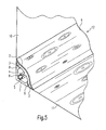
- the visible side is the surface section of a decorative profile body 1 according to the invention which the viewer sees in the installed state, as for example in FIG. 5, and which is essentially completely covered by a decorative element 6 in the enclosed figures.
- Fig. 1 shows a cross section of the decorative profile body 1 according to the invention with sealing function, preferably for the wall connection profile 12 shown in Figures 4 and 5, with a support portion 2, which has a curvature on the visible side and the edge of two formed as sealing lips, flexible sealing portions 3 edges is.
- the underside of the decorative profile body 1 is opposite to the visible side and not visible to the viewer in the installed state of the decorative profile body 1.
- the support section 2 which is preferably extruded in one piece, on the underside a formed as a profile rib mounting portion 4 with a mounting projection 5.
- This fastening projection 5 is intended to be in a correspondingly profiled guide portion 8 of a preferably integrally extruded profile body 7, as shown in Fig. 4, engaged and received therein positively.
- the profile body 7 forms the L-shaped lower part of the two-part wall connection profile 12.
- the decor profile body 1 forms the associated upper part.
- the support portion 2 of the decorative profile body 1 is preferably made of a flexible, extrudable plastic and has a harder material than the flexible sealing portions 3.
- the sealing portions 3 have approximately the shape of acute triangles in cross section and each run from the connected to the support section 2 end pointed towards its free end.
- the sealing portions 3 are profiled accordingly to have particularly flexible properties.
- the decorative element 6 is a flexible, dewaxed film and is adhesively bonded to the support section 2 and the adjacent sealing sections 3, so that it completely covers the support section 2 on the visible side and completely overlaps both sealing sections 3 on the visible side.
- a surface section of a sealing section 3 runs in alignment with a surface section of the support section 2.
- the undersides of the sealing portions 3 are aligned with the underside of the support section 2. Since the decorative element 6 completely overlaps the surface sections of the sealing sections 3 on the visible side, the sealing sections 3 are not visible from the visible side.
- the decorative element 6 may, for example, be materially connected to the support section 2 and / or at least one sealing section 3, which is particularly suitable when both the support section 2 and the sealing sections 3 are made of plastic and are produced, for example, in coextrusion methods known per se , It is also possible that the sealing portions 3 are not directly connected to the support portion 2, but only indirectly, via the decorative element 6, with the support portion 2.
- the decorative element 6 is made of a harder material than the sealing portions 3 in order to give the sealing portions 3 resilient properties, and to increase the contact pressure of the sealing portions 3 on the surfaces to be sealed 10 and 11 ( Figure 4) in the installed state of the decorative profile body 1.
- tops or bottoms of the sealing portions 3 are aligned with the top or the bottom of the support portion 2 and the decorative element 6, the top of the sealing portion 3 on the Fully overlapped visible side.
- FIG. 2b shows a special embodiment in which the decorative element 6 is embedded in the material of the decorative profile body 1, in particular between the sealing sections 3, and the sealing sections 3 are substantially completely overlapped on the visible side.
- the adjacent surface sections on the upper side or underside of the support section 2 and on the upper sides or lower sides of the sealing sections 3 each extend in alignment with one another.
- the surface of the decorative element 6 is aligned with the adjacent surface portions of the sealing portions 3 at their tapered ends. For a smooth transition between the decorative element 6 and the sealing portions 3 is accomplished.
- FIGS. 3a to 3d show cross sections of preferred embodiments of the decorative profile body 1 according to the invention.
- the upper and lower sides of the carrier section 2 and the upper and lower sides of the adjacent sealing sections 3 are aligned with one another.
- the decorative element 6 completely covers the upper side of the carrier section 2 and upper sides of the sealing sections 3 on the respective visible side of the decorative profile body 1.
- the decorative element 6 overlaps the sealing portions 3 on the respective visible side only in sections.
- FIG. 3 a shows an exemplary embodiment of the decorative profile body 1 according to the invention with a carrier section 2 that is essentially S-shaped in the sectional view.
- 3b shows an exemplary embodiment of the decorative profile body 1 according to the invention with a carrier section 2 that is substantially straight in the sectional view.
- 3c shows a further embodiment of the decorative profile body 1 according to the invention with a support section 2 convexly curved in the sectional view on the visible side.
- FIG. 3d shows a further exemplary embodiment of the decorative profile body 1 according to the invention, with a carrier section 2 concavely curved in the sectional view on the visible side.
- FIG. 4 shows a sectional view of the wall connection profile 12 according to the invention with the above-described decorative profile body 1 from FIG. 3b, which is clipped into a transition region between a kitchen worktop 11 and a wall 10 in the guide section 8 of the guide body 7.
- the guide body 7 has at its edges on two support portions 9 in order to support the edge regions of the decorative profile body 1 at the bottom.
- the sealing portions 3 are in each case under prestress against the surfaces to be sealed of the kitchen worktop 11 and the wall 10, in order to seal the gap between the decorative profile body 1 and the kitchen worktop 11 and the wall 10.
- the decorative element 6 of the decorative profile body 1 completely covers and overlaps the carrier section 2 and the edge-side sealing sections 3 on the visible side of the decorative profile body 1.
- FIG. 5 shows an installation situation of a wall connection profile according to the invention with the decor profile body 1 shown in FIG. 3c.
- the guide body 7 is fastened, preferably screwed, in the transition area from the wall 10 to the kitchen worktop 11 at least on one of the two surfaces 10 or 11 to be sealed.
- the fastening projection 5 on the attachment portion 4 of the decorative profile body 1 is clipped into the guide portion 8 of the guide body 7 and is positively received therein.
- the decorative element 6 on the visible side of the decorative profile body 1 is color and structurally adapted to the decor of the kitchen worktop 11.
- the decorative element 6 completely overlaps the sealing sections 3 and provides for an optically and aesthetically pleasing transition between the kitchen worktop 11 and the decorative profile body 1.
Landscapes
- Engineering & Computer Science (AREA)
- Architecture (AREA)
- Health & Medical Sciences (AREA)
- Epidemiology (AREA)
- Public Health (AREA)
- Civil Engineering (AREA)
- Structural Engineering (AREA)
- Finishing Walls (AREA)
- Building Environments (AREA)
Applications Claiming Priority (1)
| Application Number | Priority Date | Filing Date | Title |
|---|---|---|---|
| DE102005011439A DE102005011439A1 (de) | 2005-03-12 | 2005-03-12 | Dekorprofilkörper mit Dichtfunktion |
Publications (2)
| Publication Number | Publication Date |
|---|---|
| EP1700971A2 true EP1700971A2 (fr) | 2006-09-13 |
| EP1700971A3 EP1700971A3 (fr) | 2009-08-12 |
Family
ID=36589092
Family Applications (1)
| Application Number | Title | Priority Date | Filing Date |
|---|---|---|---|
| EP06004935A Withdrawn EP1700971A3 (fr) | 2005-03-12 | 2006-03-10 | Corps profilé décoratif avec fonction d'étanchéité |
Country Status (2)
| Country | Link |
|---|---|
| EP (1) | EP1700971A3 (fr) |
| DE (1) | DE102005011439A1 (fr) |
Cited By (6)
| Publication number | Priority date | Publication date | Assignee | Title |
|---|---|---|---|---|
| WO2009124744A2 (fr) | 2008-04-09 | 2009-10-15 | Rehau Ag + Co | Procédé de production d'un profilé décoratif sur lequel est appliqué au moins un élément fonctionnel |
| EP2037056A3 (fr) * | 2007-09-11 | 2011-12-21 | W. Döllken & Co. GmbH | Plinthe |
| US20140093689A1 (en) * | 2009-07-27 | 2014-04-03 | Gregory A. Amundson | Flexible corner trim product |
| FR3032988A1 (fr) * | 2015-02-19 | 2016-08-26 | Plastiques Des Neiges | Dispositif de protection de la base d'un mur ou d'une cloison |
| US20170059149A1 (en) * | 2015-08-31 | 2017-03-02 | Gregory A. Amundson | Inside corner trim product |
| EP3795775B1 (fr) * | 2019-09-13 | 2022-08-24 | APU Schönberg GmbH | Plinthe, corniche et panneau isolant pour cadre de fenêtre ou de porte |
Families Citing this family (4)
| Publication number | Priority date | Publication date | Assignee | Title |
|---|---|---|---|---|
| DE202008015223U1 (de) | 2008-11-05 | 2010-03-25 | Sondermann, Frank | Sockelleiste zum Abdecken eines Belagsrandes |
| DE102011011079A1 (de) * | 2011-02-11 | 2012-08-16 | Guido Schulte | Fußbodenleiste sowie Verfahren zur Herstellung einer Fußbodenleiste |
| DE102012200439A1 (de) * | 2012-01-12 | 2013-07-18 | Laminatepark Gmbh & Co. Kg | Zweiteiliges Abschlussprofil |
| DE102015106241A1 (de) | 2015-04-23 | 2016-10-27 | Döllken-Kunststoffverarbeitung Gmbh | Verfahren zum Herstellen eines dekorativen Profilkörpers, insbesondere einer Kantenleiste |
Citations (1)
| Publication number | Priority date | Publication date | Assignee | Title |
|---|---|---|---|---|
| DE19946617A1 (de) | 1999-09-29 | 2001-05-03 | Schock & Co Gmbh | Dekorprofil |
Family Cites Families (9)
| Publication number | Priority date | Publication date | Assignee | Title |
|---|---|---|---|---|
| DE1987358U (de) * | 1968-06-12 | tielsa Möbel-Werke G.m.b.H. a Co. K.G., 4903 Schötmar | Wandabschlußleiste | |
| DE7042609U (de) * | 1971-05-27 | Bronowski H | Fußbodenleiste | |
| DE1920533U (de) * | 1963-09-07 | 1965-07-29 | Schock & Co Gmbh | Sockelleiste. |
| DE19506245A1 (de) * | 1995-02-23 | 1996-08-29 | Saar Gummiwerk Gmbh | Dichtungsprofil mit beschichteter Dichtwulst |
| GB9510360D0 (en) * | 1995-05-23 | 1995-07-19 | Mckechnie Uk Ltd | Sealing assembly |
| DE20121632U1 (de) * | 2001-12-14 | 2003-02-13 | Bánhidy, Kálmán, Dipl.-Ing., 40699 Erkrath | Wandanschlußprofil |
| DE20206984U1 (de) * | 2002-05-03 | 2002-09-12 | W. Döllken & Co. GmbH, 45964 Gladbeck | Kernsockelleiste |
| DE20305171U1 (de) * | 2003-03-31 | 2003-10-30 | BOLTA Industrie- und Bauprofile GmbH, 94513 Schönberg | Hartschaum-Sockelleiste |
| DE20312315U1 (de) * | 2003-08-09 | 2003-11-13 | W. Döllken & Co. GmbH, 45964 Gladbeck | Abdeckleiste |
-
2005
- 2005-03-12 DE DE102005011439A patent/DE102005011439A1/de not_active Withdrawn
-
2006
- 2006-03-10 EP EP06004935A patent/EP1700971A3/fr not_active Withdrawn
Patent Citations (1)
| Publication number | Priority date | Publication date | Assignee | Title |
|---|---|---|---|---|
| DE19946617A1 (de) | 1999-09-29 | 2001-05-03 | Schock & Co Gmbh | Dekorprofil |
Cited By (13)
| Publication number | Priority date | Publication date | Assignee | Title |
|---|---|---|---|---|
| EP2037056A3 (fr) * | 2007-09-11 | 2011-12-21 | W. Döllken & Co. GmbH | Plinthe |
| WO2009124744A2 (fr) | 2008-04-09 | 2009-10-15 | Rehau Ag + Co | Procédé de production d'un profilé décoratif sur lequel est appliqué au moins un élément fonctionnel |
| WO2009124744A3 (fr) * | 2008-04-09 | 2011-03-03 | Rehau Ag + Co | Procédé de production d'un profilé décoratif sur lequel est appliqué au moins un élément fonctionnel |
| US10550584B2 (en) | 2009-07-27 | 2020-02-04 | Gregory A. Amundson | Flexible corner trim product |
| US9783999B2 (en) * | 2009-07-27 | 2017-10-10 | Gregory A Amundson | Flexible corner trim product |
| US20140093689A1 (en) * | 2009-07-27 | 2014-04-03 | Gregory A. Amundson | Flexible corner trim product |
| US11401720B2 (en) | 2009-07-27 | 2022-08-02 | Amundson Technology, Llc | Flexible corner trim product |
| FR3032988A1 (fr) * | 2015-02-19 | 2016-08-26 | Plastiques Des Neiges | Dispositif de protection de la base d'un mur ou d'une cloison |
| US20170059149A1 (en) * | 2015-08-31 | 2017-03-02 | Gregory A. Amundson | Inside corner trim product |
| US9765960B2 (en) * | 2015-08-31 | 2017-09-19 | Gregory A. Amundson | Inside corner trim product |
| US10054304B2 (en) | 2015-08-31 | 2018-08-21 | Gregory A. Amundson | Trim product and methods of manufacturing |
| US11193668B2 (en) | 2015-08-31 | 2021-12-07 | Gregory A. Amundson | Inside corner trim product |
| EP3795775B1 (fr) * | 2019-09-13 | 2022-08-24 | APU Schönberg GmbH | Plinthe, corniche et panneau isolant pour cadre de fenêtre ou de porte |
Also Published As
| Publication number | Publication date |
|---|---|
| DE102005011439A1 (de) | 2006-09-14 |
| EP1700971A3 (fr) | 2009-08-12 |
Similar Documents
| Publication | Publication Date | Title |
|---|---|---|
| EP0615875B1 (fr) | Procédé pour fabriquer un volet rigide pour toit de véhicule et volet fabriqué d'après ce procédé | |
| DE3618278A1 (de) | Glasscheibe mit im randbereich aufgesteckter profilleiste | |
| WO2004056598A1 (fr) | Dispositif d'étanchéité, notamment pour étancher les glaces d'un véhicule | |
| WO2011029207A1 (fr) | Procédé de production d'un composant présentant un élément décoratif plan, et composant doté d'un élément décoratif plan | |
| DE20321549U1 (de) | Dicht-, Trimm- oder Führungsleiste | |
| DE2937454A1 (de) | Verbundprofil, insbesondere fuer fenster, tueren und fassaden sowie verfahren zur herstellung des verbundprofils | |
| EP1700971A2 (fr) | Corps profilé décoratif avec fonction d'étanchéité | |
| DE202014102150U1 (de) | Dachrelinganordnung für ein Kraftfahrzeug | |
| DE60320276T9 (de) | Dichtungs-, zier- oder führungsstreifen | |
| WO2016131615A1 (fr) | Bande de chant | |
| DD291963A5 (de) | Spaltdichtung fuer scheiben sowie fenster- oder windschutzscheiben-anordnung an einer fahrzeugkarosserie | |
| DE3204351A1 (de) | Befestigungssystem fuer fixe fensterscheiben von fahrzeugen im allgemeinen, insbesondere von kraftfahrzeugen | |
| WO2006042492A1 (fr) | Bande de matiere destinee a l'etancheite, au revetement ou au guidage | |
| DE102021131727A1 (de) | Fahrzeugscheibenanordnung | |
| DE102005017744A1 (de) | Abdeckung an einem Kraftfahrzeugaussenteil sowie entsprechendes Verfahren zur Herstellung und entsprechende Verwendung | |
| DE3612294C2 (fr) | ||
| DE10146628B4 (de) | Dichtungsanordnung zum Abdichten des Fensterschachts eines Kraftfahrzeugs | |
| DE102015007294B3 (de) | Scheibenanordnung, insbesondere Karosserie-Scheibenanordnung | |
| DE29921490U1 (de) | Stranggepreßtes Hohlprofil aus Kunststoff oder Metall zur Herstellung von Fenstern, Türen, Fassaden o.dgl. | |
| EP1717082B1 (fr) | Joint d'étanchéité avec une couche de surface | |
| DE10053678B4 (de) | Anordnung aus einer Fahrzeugfensterscheibe und einem anschließenden Abdeckelement | |
| EP3368357B1 (fr) | Ensemble de fenêtre | |
| DE20016842U1 (de) | Profilleiste, insbesondere Kantenleiste für die Möbelindustrie | |
| DE10259842A1 (de) | Dichtung, insbesondere zum Abdichten von Fensterscheiben eines Kraftfahrzeugs | |
| DE69606727T2 (de) | Dichtung und ihr Herstellungsverfahren |
Legal Events
| Date | Code | Title | Description |
|---|---|---|---|
| PUAI | Public reference made under article 153(3) epc to a published international application that has entered the european phase |
Free format text: ORIGINAL CODE: 0009012 |
|
| AK | Designated contracting states |
Kind code of ref document: A2 Designated state(s): AT BE BG CH CY CZ DE DK EE ES FI FR GB GR HU IE IS IT LI LT LU LV MC NL PL PT RO SE SI SK TR |
|
| AX | Request for extension of the european patent |
Extension state: AL BA HR MK YU |
|
| PUAL | Search report despatched |
Free format text: ORIGINAL CODE: 0009013 |
|
| AK | Designated contracting states |
Kind code of ref document: A3 Designated state(s): AT BE BG CH CY CZ DE DK EE ES FI FR GB GR HU IE IS IT LI LT LU LV MC NL PL PT RO SE SI SK TR |
|
| AX | Request for extension of the european patent |
Extension state: AL BA HR MK YU |
|
| 17Q | First examination report despatched |
Effective date: 20090922 |
|
| AKX | Designation fees paid |
Designated state(s): AT BE BG CH CY CZ DE DK EE ES FI FR GB GR HU IE IS IT LI LT LU LV MC NL PL PT RO SE SI SK TR |
|
| STAA | Information on the status of an ep patent application or granted ep patent |
Free format text: STATUS: THE APPLICATION IS DEEMED TO BE WITHDRAWN |
|
| 18D | Application deemed to be withdrawn |
Effective date: 20121002 |