EP1700975A1 - Fenstergerüst - Google Patents
Fenstergerüst Download PDFInfo
- Publication number
- EP1700975A1 EP1700975A1 EP06290190A EP06290190A EP1700975A1 EP 1700975 A1 EP1700975 A1 EP 1700975A1 EP 06290190 A EP06290190 A EP 06290190A EP 06290190 A EP06290190 A EP 06290190A EP 1700975 A1 EP1700975 A1 EP 1700975A1
- Authority
- EP
- European Patent Office
- Prior art keywords
- vertical
- opening
- horizontal
- wall
- scaffolding
- Prior art date
- Legal status (The legal status is an assumption and is not a legal conclusion. Google has not performed a legal analysis and makes no representation as to the accuracy of the status listed.)
- Granted
Links
Images

Classifications
-
- E—FIXED CONSTRUCTIONS
- E04—BUILDING
- E04G—SCAFFOLDING; FORMS; SHUTTERING; BUILDING IMPLEMENTS OR AIDS, OR THEIR USE; HANDLING BUILDING MATERIALS ON THE SITE; REPAIRING, BREAKING-UP OR OTHER WORK ON EXISTING BUILDINGS
- E04G3/00—Scaffolds essentially supported by building constructions, e.g. adjustable in height
- E04G3/18—Scaffolds essentially supported by building constructions, e.g. adjustable in height supported by cantilevers or other provisions mounted in openings in the building, e.g. window openings
-
- E—FIXED CONSTRUCTIONS
- E04—BUILDING
- E04G—SCAFFOLDING; FORMS; SHUTTERING; BUILDING IMPLEMENTS OR AIDS, OR THEIR USE; HANDLING BUILDING MATERIALS ON THE SITE; REPAIRING, BREAKING-UP OR OTHER WORK ON EXISTING BUILDINGS
- E04G3/00—Scaffolds essentially supported by building constructions, e.g. adjustable in height
- E04G3/28—Mobile scaffolds; Scaffolds with mobile platforms
Definitions
- the present invention relates to work platform supports and more particularly to external scaffolds.
- a scaffolding able to bear on a substantially vertical wall having an outer face and an inner face, delimiting an inner zone and an outer zone, in which is formed at least one opening with which said scaffolding cooperates.
- Such scaffolds are used when working on an exterior wall.
- scaffolding is maintained by cooperating with one or more openings in a wall, such as windows.
- US 4,079,813 describes a folding scaffold able to cooperate with a single window supported on the outer and inner faces of the wall.
- This scaffolding has two major drawbacks: on the one hand, the platform has a very small surface, which limits the number of people who can climb on the platform as well as the useful surface, and on the other hand, it does not It is not possible to adjust the vertical position of the platform, which may prevent a worker from accessing the area above the window bay.
- the document FR 959 745 represents a scaffolding of windows able to cooperate with two windows, whose platform also has the disadvantage, when the scaffolding is installed, not being able to be adjustable in height.
- the object of the invention is to provide a scaffold substantially free from the disadvantages mentioned above.
- the vertical position of the platform can be adjusted so that the user can access a larger wall surface than in the case where the platform is fixed.
- each opening cooperates with a fixing element and the horizontal platform of the scaffolding is supported by the horizontal branches of the brackets of the fastening assemblies.
- angles are adjustable in height, it is not necessary that the lower edges of the openings are arranged on the same height because it is always possible to position the platform horizontally by adjusting the vertical position of each horizontal branch supporting the plate -form.
- the multiple support means give the scaffold a certain stability.
- an already known scaffold tends to pivot about a horizontal axis passing through lower support means.
- the judicious position of the first and second support means prevents this pivoting by bearing on the outer and inner faces of the wall, respectively below and above the opening so as to block the pivoting of the scaffolding .
- the inner vertical bar further comprises third support means adapted to bear on the inner face of the wall, below the opening.
- the third support means are located at a height between that of the lower edge of the opening and that of the first support means.
- the second and third support means are located at both ends of the inner vertical bar.
- the horizontal bar further comprises fourth support means adapted to take up vertically on a lower edge of an opening.
- these fourth support means are used to lock the scaffold vertically. In particular, they prevent the scaffold from moving down due to the scaffold's own weight and / or the weight of the user, which allows the scaffold to be used safely.
- the first, second, third and fourth bearing means comprise at least one adjustable rubber support pad.
- the rubber prevents the pad from slipping on the wall, transversely to the direction of support. Any other material with a high coefficient of friction may be used.
- the platform is able to be positioned below the level of the lower edge of an opening.
- the user can easily access the portion below the opening, without having to disassemble or move the scaffold.
- the platform is able to be positioned above the level of the upper rim of an opening.
- the user has the opportunity to access the portion above the opening, without having to disassemble or move the scaffold.
- the vertical branch of a bracket is able to slide vertically in a channel formed in the outer vertical bar.
- the channel preferably extends along the outer vertical bar, so that the vertical leg can slide vertically over the entire length of the outer vertical bar.
- the vertical leg comprises a plurality of fastening means adapted to cooperate with fastening means disposed on the outer vertical bar so as to fix the vertical leg in the channel of different heights.
- the angle can be positioned in at least two ways relative to the outer vertical bar so that the horizontal leg can be disposed either above or below the vertical leg.
- the scaffold comprises at least two fastening assemblies.
- each fastener cooperates with an opening formed in the wall, but however, two fastener assemblies can cooperate with one and the same opening.
- the scaffolding cooperates with two openings formed in the wall and disposed substantially at the same height.
- the scaffolding preferably comprises two sets of separate fasteners, the platform is supported by the two horizontal branches of the two angles of two sets of fastening cooperating with the two openings and that the position of the platform is adjustable in a vertical direction.
- Adjusting the vertical position of the platform is done by positioning the angles so that their horizontal branches are arranged in the same horizontal plane.
- the scaffolding is able to cooperate with two, three or more openings provided they are arranged at about the same height.
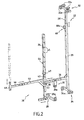
- the scaffold 10 shown here is designed to cooperate with two windows bays 12, 14 formed substantially at the same height in an exterior wall 16 of a house.
- the scaffold 10 cooperated with a single opening, or with a plurality of openings disposed substantially at the same height.
- the two window openings 12, 14 have different dimensions and their lower edges are not arranged in the same horizontal plane.
- This representation makes it possible to clearly show the adaptability of the scaffolding according to the invention to any type of window bays.
- the scaffold according to the invention advantageously allows to cooperate with several openings arranged substantially but not exactly the same height.
- the scaffold 10 supports a horizontal platform 18 which extends along the wall 16 in a plane substantially orthogonal to the surface of the wall for a distance between the vertical edges furthest from the two openings 12, 14 forming the bays. window 12,14.
- This platform 18 is intended to support one or more users 20.
- the horizontal platform 18 is supported by two fastening assemblies 22,24 disposed substantially at each end of said platform and each cooperating with a window opening.
- the scaffold 10 according to the invention bears on the outside face of the wall 16 and, consequently, it is not necessary for the scaffolding 10 to bear on the ground.
- each fastening element 22,24 is intended to cooperate with a window bay so as to be secured to the wall 16.
- each fastening element 22,24 is adapted to bear against the outer faces 25 and 27 of inner wall 16.
- Each fastener 22,24 comprises an outer vertical bar 26 whose lower end comprises first bearing means 28 preferably comprising a pair of rubber bearing pads 28a, each of the bearing pads preferably having the shape of a thick disc forming a bearing surface disposed in a substantially vertical plane.
- the fastening element 22 further comprises an inner vertical bar 29 which has second support means 32 at its upper end and third support means 34 at its lower end.
- the length of the inner vertical bar 29 can be adjusted by means of a vertical telescopic arm 29 ', which is integral with the inner vertical bar, in which it slides by means of a screw 60 clamping.
- the second support means 32 comprise a pair of rubber bearing pads 32a, each of the support pads also preferably having the form of thick discs forming bearing surfaces disposed in a substantially vertical plane.
- the second support means 32 may comprise an additional pair of rubber bearing pads 33a, each of the support pads preferably being in the form of thick discs forming bearing surfaces disposed in a substantially horizontal plane.
- the third support means 34 comprise a pair of rubber bearing pads 34a, each of the support pads preferably being in the form of thick discs forming bearing surfaces disposed in a substantially vertical plane.
- the clamping screw 60 may comprise at its end a bearing pad 60a similar to those described above.
- the bearing pads 28a, 32a, 34a of the first, second and third bearing means and the bearing pad 60a associated with the clamping screw 60, are arranged in such a way that their respective bearing surfaces are in contact with each other. -a-vis.
- the outer 26 and inner 29 vertical bars are integrally connected together via the ends of a transverse horizontal bar 36.
- the horizontal bar 36 is fixed substantially preferentially to two-thirds of the length of the inner vertical bar 29.
- the horizontal bar 36 is fixed substantially to two-thirds of the length of the outer vertical bar 26.
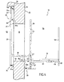
- the length of the horizontal bar 36 can be adjusted, preferably by means of a telescopic arm 36 ' visible in Figure 2, so as to adapt the fastener to the thickness of the wall 16.
- the second support means 32 it is advantageous for the second support means 32 to be positioned between the horizontal bar 36 and the first support means 28, as shown in FIG . 2.
- the horizontal bar 36 preferably but not necessarily has fourth bearing means 30 comprising a rubber bearing pad 30a having the shape of a thick disk forming a bearing surface disposed in a substantially horizontal plane whose function will be explained. below.
- Each fastening element further comprises an angle bracket 38 adjustably fixed to the outer vertical bar 26.
- This bracket 38 comprises a horizontal branch 40 and a vertical branch 42 able to slide vertically in a channel 44 formed in the outer vertical bar 26.
- the outer vertical bar 26 has, in a transverse plane, a section substantially shaped "U".
- the outer vertical bar 26 has a plurality of transverse bores 45 disposed periodically over substantially its entire length.
- the vertical leg 42 of the bracket 38 also has a plurality of transverse bores (not shown here) and the fixing of the outer vertical bar 26 with the vertical leg 42 of the bracket 38 can be achieved with pins 47 traversing transversely said vertical bar 26 and said branch 42 through said bores.
- the horizontal leg 40 of the bracket 38 is intended to support the platform 18. More specifically, it is the two horizontal branches 40,40 ' of the two brackets 38,38' of two sets of fasteners 22,24 that support the platform 18.
- the horizontal branch 40 of the bracket 38 is advantageously unfoldable in the direction of its length so as to adapt to the width of the platform 18.
- the horizontal leg 40 comprises a telescopic arm 46 which is provided at its end with a vertical rod holder 48, intended to hold one of the two horizontal arms of a barrier 50 forming guardrails, shown in FIG .
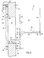
- Figure 3 shows a sectional side view of the window bay on which is mounted a fastener 22,24.
- the wall 16 of the house shown in this figure delimits an inner zone 52 and an outer zone 54.
- the outer vertical bar 26 is disposed in the outer zone 54, the rubber pad 28a of the first support means being disposed below the window bay.
- the inner vertical bar 29 is disposed in the inner zone 52, the buffer 32a of the second support means 32 bearing above the window bay and the buffers 34a of the third support means 34 bearing support below the window bay. It is therefore understood that the inner vertical bar 29 preferably has a length substantially greater than the height of the window bay.
- the fixing element 22 is arranged so that the horizontal bar 36 passes through the window bay, and the buffer 30 of the fourth support means is arranged to bear on a lower edge 56 of the window bay .
- the assembly formed by the rubber bearing pads 28a, 32a of the first and second support means 28, 32 allows advantageously to prevent the fastening element 22 from pivoting in a counterclockwise direction.
- the assembly formed by the rubber support pads 28a, 34a of the first and third support means 28,34 advantageously allows to tighten the clamp part of the wall that lies beneath the window opening.
- the third support means 34 are not systematically necessary, however they improve the blocking of the scaffolding by providing additional support and improves the safety of the scaffolding.
- the rubber pad 30a of the fourth support means 30 for their part makes it possible to lock the fastening element vertically 22 by resting on the lower edge of the window bay.
- the fourth support means 30 can be horizontally displaceable in the direction of the transverse horizontal bar 36, so as to be able to adapt to the shape of the lower edge, for example 56.
- the support pad 60a associated with the clamping screw 60 is arranged so as to be able to bear on the inside face 27 of the wall 16 , above the bay of window 12.
- the support pads 33a located at the upper end of the inner vertical bar 29 and arranged in a horizontal plane, are able to bear against a ceiling 17.
- all the support means are adjustable vertically and / or horizontally so as to adapt to the shape of the outer and inner faces of the wall 16, and the lower edge of the window bay.
- the angle 38 can be positioned at least two ways with respect to the outer vertical bar so that the horizontal leg 40 can be disposed either above or below the vertical leg 44.
- the angle is positioned in such a way that the horizontal branch 40 is disposed above the vertical branch 42.
- the angle is positioned so that the horizontal leg 40 is disposed below the vertical leg.
- the angle 38 is fixed to the lower end of the outer vertical bar 26 so that it is no longer possible to lower the vertical leg 42 of the bracket 38.
Landscapes
- Engineering & Computer Science (AREA)
- Architecture (AREA)
- Mechanical Engineering (AREA)
- Civil Engineering (AREA)
- Structural Engineering (AREA)
- Ladders (AREA)
- Glass Compositions (AREA)
- Electrical Discharge Machining, Electrochemical Machining, And Combined Machining (AREA)
- Farming Of Fish And Shellfish (AREA)
- Wing Frames And Configurations (AREA)
- Special Wing (AREA)
Applications Claiming Priority (1)
| Application Number | Priority Date | Filing Date | Title |
|---|---|---|---|
| FR0501027A FR2881450B1 (fr) | 2005-02-02 | 2005-02-02 | Echafaudage de fenetres |
Publications (2)
| Publication Number | Publication Date |
|---|---|
| EP1700975A1 true EP1700975A1 (de) | 2006-09-13 |
| EP1700975B1 EP1700975B1 (de) | 2009-04-01 |
Family
ID=35005755
Family Applications (1)
| Application Number | Title | Priority Date | Filing Date |
|---|---|---|---|
| EP06290190A Expired - Lifetime EP1700975B1 (de) | 2005-02-02 | 2006-02-02 | Fenstergerüst |
Country Status (4)
| Country | Link |
|---|---|
| EP (1) | EP1700975B1 (de) |
| AT (1) | ATE427392T1 (de) |
| DE (1) | DE602006005969D1 (de) |
| FR (1) | FR2881450B1 (de) |
Cited By (2)
| Publication number | Priority date | Publication date | Assignee | Title |
|---|---|---|---|---|
| EP2246288A1 (de) | 2009-04-06 | 2010-11-03 | Ivar Ole Wik | Gütertransportvorrichtung und Anwendung |
| CN103790368A (zh) * | 2012-10-29 | 2014-05-14 | 五冶集团上海有限公司 | 简易高空作业平台搭设方法 |
Families Citing this family (4)
| Publication number | Priority date | Publication date | Assignee | Title |
|---|---|---|---|---|
| WO2008077202A1 (en) * | 2006-12-27 | 2008-07-03 | Zoran Dujakovic | Mobile scaffold for working at heights |
| WO2017075654A1 (en) | 2015-11-02 | 2017-05-11 | John Clement Preston | Loading platform |
| US11939782B2 (en) | 2020-01-21 | 2024-03-26 | Aaa Royal Construction Llc | Wall-mountable perch |
| CN113789945B (zh) * | 2021-07-19 | 2023-02-03 | 中国建筑第二工程局有限公司 | 一种可滑移式窗外施工安全操作架及其施工方法 |
Citations (7)
| Publication number | Priority date | Publication date | Assignee | Title |
|---|---|---|---|---|
| BE386576A (de) * | ||||
| FR959745A (de) | 1950-04-04 | |||
| US4079813A (en) | 1976-06-29 | 1978-03-21 | The Raymond Lee Organization, Inc. | Step-out window washer box |
| GB2141771A (en) * | 1983-05-11 | 1985-01-03 | Michael Percy Cowles | Builder's cradle |
| FR2660955A1 (fr) * | 1990-04-12 | 1991-10-18 | Step Arcadia | Passerelle de travail au-dessus du vide. |
| US5203426A (en) * | 1992-02-11 | 1993-04-20 | Sydnor Eugene E | Portable window perch assembly |
| US20030127283A1 (en) * | 2001-12-26 | 2003-07-10 | Clifton Deal | Adjustable scaffold and walkboard ladder holder |
-
2005
- 2005-02-02 FR FR0501027A patent/FR2881450B1/fr not_active Expired - Fee Related
-
2006
- 2006-02-02 AT AT06290190T patent/ATE427392T1/de not_active IP Right Cessation
- 2006-02-02 DE DE602006005969T patent/DE602006005969D1/de not_active Expired - Lifetime
- 2006-02-02 EP EP06290190A patent/EP1700975B1/de not_active Expired - Lifetime
Patent Citations (7)
| Publication number | Priority date | Publication date | Assignee | Title |
|---|---|---|---|---|
| BE386576A (de) * | ||||
| FR959745A (de) | 1950-04-04 | |||
| US4079813A (en) | 1976-06-29 | 1978-03-21 | The Raymond Lee Organization, Inc. | Step-out window washer box |
| GB2141771A (en) * | 1983-05-11 | 1985-01-03 | Michael Percy Cowles | Builder's cradle |
| FR2660955A1 (fr) * | 1990-04-12 | 1991-10-18 | Step Arcadia | Passerelle de travail au-dessus du vide. |
| US5203426A (en) * | 1992-02-11 | 1993-04-20 | Sydnor Eugene E | Portable window perch assembly |
| US20030127283A1 (en) * | 2001-12-26 | 2003-07-10 | Clifton Deal | Adjustable scaffold and walkboard ladder holder |
Cited By (3)
| Publication number | Priority date | Publication date | Assignee | Title |
|---|---|---|---|---|
| EP2246288A1 (de) | 2009-04-06 | 2010-11-03 | Ivar Ole Wik | Gütertransportvorrichtung und Anwendung |
| CN103790368A (zh) * | 2012-10-29 | 2014-05-14 | 五冶集团上海有限公司 | 简易高空作业平台搭设方法 |
| CN103790368B (zh) * | 2012-10-29 | 2016-06-01 | 五冶集团上海有限公司 | 简易高空作业平台搭设方法 |
Also Published As
| Publication number | Publication date |
|---|---|
| EP1700975B1 (de) | 2009-04-01 |
| FR2881450B1 (fr) | 2007-05-11 |
| DE602006005969D1 (de) | 2009-05-14 |
| FR2881450A1 (fr) | 2006-08-04 |
| ATE427392T1 (de) | 2009-04-15 |
Similar Documents
| Publication | Publication Date | Title |
|---|---|---|
| EP2393402B1 (de) | Antriebsschlitten für einen schiebevorhang | |
| FR3074512A1 (fr) | Dispositif d'aide a la construction d'un mur a partir d'elements de structure prefabriques, permettant l'approche, le reglage et le positionnement des elements prefabriques | |
| FR2624173A1 (fr) | Echafaudage grimpant a plate-forme constituant un tout unitaire | |
| EP1700975B1 (de) | Fenstergerüst | |
| EP0774032B1 (de) | Variabel gestaltete treppe | |
| FR3047260B1 (fr) | Garde-corps autoporte | |
| EP3141152B1 (de) | Zusammenklappbare konpakte tisch, besonders für schienenfahrzeug | |
| FR2976791A1 (fr) | Barriere de lit escamotable | |
| FR2891762A1 (fr) | Dispositif de decoupe manuelle de carrreau ou carrelage | |
| EP0734665B1 (de) | Bettgestell, mit übereinander angeordneten abklappbaren Rahmen, das mit Bodenstützen ausgestattet ist | |
| EP1052344B1 (de) | Bausatz zur Montage einer geraden Treppe und Montageverfahren unter Verwendung dieses Bausatzes | |
| FR2883018A1 (fr) | Bloc fonctionnel destine aux troncons d'un abri telescopique | |
| EP0282385B1 (de) | Vorrichtung zur Verankerung an Dachsparren bei Dacharbeiten | |
| EP3392430A1 (de) | Revisionsöffnung | |
| FR2681623A1 (fr) | Dispositif de protection pour travaux sur toiture. | |
| EP1679408A2 (de) | Gelenkvorrichtung für faltbare Platform sowie Platform mit einer solchen Vorrichtung | |
| FR2862679A1 (fr) | Escalier et echelle pliables a encombrement reduit | |
| WO2012163917A2 (fr) | Dispositif de protection modulable | |
| FR3033689A1 (fr) | Dispositif support de tringles, adaptable sur la face avant de caissons de volets roulants. | |
| EP0156663A1 (de) | Vorrichtung zum Hemmen des Rücklaufes von Skiern | |
| WO2025104329A1 (fr) | Plate-forme d'accès sécurisé | |
| FR2776005A1 (fr) | Dispositif de garde-corps de securite pour ouverture exterieure de batiment | |
| FR2537634A1 (fr) | Escalier escamotable | |
| FR3139157A1 (fr) | Butée d’arrêt, système de suspension et dispositif d’occultation comprenant au moins une telle butée | |
| FR2665098A1 (fr) | Plan de travail suspendu. |
Legal Events
| Date | Code | Title | Description |
|---|---|---|---|
| PUAI | Public reference made under article 153(3) epc to a published international application that has entered the european phase |
Free format text: ORIGINAL CODE: 0009012 |
|
| AK | Designated contracting states |
Kind code of ref document: A1 Designated state(s): AT BE BG CH CY CZ DE DK EE ES FI FR GB GR HU IE IS IT LI LT LU LV MC NL PL PT RO SE SI SK TR |
|
| AX | Request for extension of the european patent |
Extension state: AL BA HR MK YU |
|
| 17P | Request for examination filed |
Effective date: 20061130 |
|
| 17Q | First examination report despatched |
Effective date: 20070116 |
|
| AKX | Designation fees paid |
Designated state(s): AT BE BG CH CY CZ DE DK EE ES FI FR GB GR HU IE IS IT LI LT LU LV MC NL PL PT RO SE SI SK TR |
|
| GRAP | Despatch of communication of intention to grant a patent |
Free format text: ORIGINAL CODE: EPIDOSNIGR1 |
|
| GRAS | Grant fee paid |
Free format text: ORIGINAL CODE: EPIDOSNIGR3 |
|
| GRAA | (expected) grant |
Free format text: ORIGINAL CODE: 0009210 |
|
| AK | Designated contracting states |
Kind code of ref document: B1 Designated state(s): AT BE BG CH CY CZ DE DK EE ES FI FR GB GR HU IE IS IT LI LT LU LV MC NL PL PT RO SE SI SK TR |
|
| REG | Reference to a national code |
Ref country code: GB Ref legal event code: FG4D Free format text: NOT ENGLISH |
|
| REG | Reference to a national code |
Ref country code: CH Ref legal event code: EP |
|
| REG | Reference to a national code |
Ref country code: IE Ref legal event code: FG4D Free format text: LANGUAGE OF EP DOCUMENT: FRENCH |
|
| REF | Corresponds to: |
Ref document number: 602006005969 Country of ref document: DE Date of ref document: 20090514 Kind code of ref document: P |
|
| PG25 | Lapsed in a contracting state [announced via postgrant information from national office to epo] |
Ref country code: SI Free format text: LAPSE BECAUSE OF FAILURE TO SUBMIT A TRANSLATION OF THE DESCRIPTION OR TO PAY THE FEE WITHIN THE PRESCRIBED TIME-LIMIT Effective date: 20090401 |
|
| NLV1 | Nl: lapsed or annulled due to failure to fulfill the requirements of art. 29p and 29m of the patents act | ||
| REG | Reference to a national code |
Ref country code: IE Ref legal event code: FD4D |
|
| PG25 | Lapsed in a contracting state [announced via postgrant information from national office to epo] |
Ref country code: PT Free format text: LAPSE BECAUSE OF FAILURE TO SUBMIT A TRANSLATION OF THE DESCRIPTION OR TO PAY THE FEE WITHIN THE PRESCRIBED TIME-LIMIT Effective date: 20090902 Ref country code: EE Free format text: LAPSE BECAUSE OF FAILURE TO SUBMIT A TRANSLATION OF THE DESCRIPTION OR TO PAY THE FEE WITHIN THE PRESCRIBED TIME-LIMIT Effective date: 20090401 Ref country code: LT Free format text: LAPSE BECAUSE OF FAILURE TO SUBMIT A TRANSLATION OF THE DESCRIPTION OR TO PAY THE FEE WITHIN THE PRESCRIBED TIME-LIMIT Effective date: 20090401 Ref country code: ES Free format text: LAPSE BECAUSE OF FAILURE TO SUBMIT A TRANSLATION OF THE DESCRIPTION OR TO PAY THE FEE WITHIN THE PRESCRIBED TIME-LIMIT Effective date: 20090712 Ref country code: FI Free format text: LAPSE BECAUSE OF FAILURE TO SUBMIT A TRANSLATION OF THE DESCRIPTION OR TO PAY THE FEE WITHIN THE PRESCRIBED TIME-LIMIT Effective date: 20090401 Ref country code: AT Free format text: LAPSE BECAUSE OF FAILURE TO SUBMIT A TRANSLATION OF THE DESCRIPTION OR TO PAY THE FEE WITHIN THE PRESCRIBED TIME-LIMIT Effective date: 20090401 |
|
| PG25 | Lapsed in a contracting state [announced via postgrant information from national office to epo] |
Ref country code: NL Free format text: LAPSE BECAUSE OF FAILURE TO SUBMIT A TRANSLATION OF THE DESCRIPTION OR TO PAY THE FEE WITHIN THE PRESCRIBED TIME-LIMIT Effective date: 20090401 Ref country code: IS Free format text: LAPSE BECAUSE OF FAILURE TO SUBMIT A TRANSLATION OF THE DESCRIPTION OR TO PAY THE FEE WITHIN THE PRESCRIBED TIME-LIMIT Effective date: 20090801 Ref country code: LV Free format text: LAPSE BECAUSE OF FAILURE TO SUBMIT A TRANSLATION OF THE DESCRIPTION OR TO PAY THE FEE WITHIN THE PRESCRIBED TIME-LIMIT Effective date: 20090401 Ref country code: PL Free format text: LAPSE BECAUSE OF FAILURE TO SUBMIT A TRANSLATION OF THE DESCRIPTION OR TO PAY THE FEE WITHIN THE PRESCRIBED TIME-LIMIT Effective date: 20090401 Ref country code: SE Free format text: LAPSE BECAUSE OF FAILURE TO SUBMIT A TRANSLATION OF THE DESCRIPTION OR TO PAY THE FEE WITHIN THE PRESCRIBED TIME-LIMIT Effective date: 20090701 |
|
| PG25 | Lapsed in a contracting state [announced via postgrant information from national office to epo] |
Ref country code: CZ Free format text: LAPSE BECAUSE OF FAILURE TO SUBMIT A TRANSLATION OF THE DESCRIPTION OR TO PAY THE FEE WITHIN THE PRESCRIBED TIME-LIMIT Effective date: 20090401 Ref country code: RO Free format text: LAPSE BECAUSE OF FAILURE TO SUBMIT A TRANSLATION OF THE DESCRIPTION OR TO PAY THE FEE WITHIN THE PRESCRIBED TIME-LIMIT Effective date: 20090401 Ref country code: IE Free format text: LAPSE BECAUSE OF FAILURE TO SUBMIT A TRANSLATION OF THE DESCRIPTION OR TO PAY THE FEE WITHIN THE PRESCRIBED TIME-LIMIT Effective date: 20090401 Ref country code: DK Free format text: LAPSE BECAUSE OF FAILURE TO SUBMIT A TRANSLATION OF THE DESCRIPTION OR TO PAY THE FEE WITHIN THE PRESCRIBED TIME-LIMIT Effective date: 20090401 |
|
| PLBE | No opposition filed within time limit |
Free format text: ORIGINAL CODE: 0009261 |
|
| STAA | Information on the status of an ep patent application or granted ep patent |
Free format text: STATUS: NO OPPOSITION FILED WITHIN TIME LIMIT |
|
| PG25 | Lapsed in a contracting state [announced via postgrant information from national office to epo] |
Ref country code: SK Free format text: LAPSE BECAUSE OF FAILURE TO SUBMIT A TRANSLATION OF THE DESCRIPTION OR TO PAY THE FEE WITHIN THE PRESCRIBED TIME-LIMIT Effective date: 20090401 |
|
| 26N | No opposition filed |
Effective date: 20100105 |
|
| PG25 | Lapsed in a contracting state [announced via postgrant information from national office to epo] |
Ref country code: BG Free format text: LAPSE BECAUSE OF FAILURE TO SUBMIT A TRANSLATION OF THE DESCRIPTION OR TO PAY THE FEE WITHIN THE PRESCRIBED TIME-LIMIT Effective date: 20090701 |
|
| BERE | Be: lapsed |
Owner name: THEVENIN SA Effective date: 20100228 |
|
| REG | Reference to a national code |
Ref country code: CH Ref legal event code: PL |
|
| PG25 | Lapsed in a contracting state [announced via postgrant information from national office to epo] |
Ref country code: MC Free format text: LAPSE BECAUSE OF NON-PAYMENT OF DUE FEES Effective date: 20100301 Ref country code: CH Free format text: LAPSE BECAUSE OF NON-PAYMENT OF DUE FEES Effective date: 20100228 Ref country code: GR Free format text: LAPSE BECAUSE OF FAILURE TO SUBMIT A TRANSLATION OF THE DESCRIPTION OR TO PAY THE FEE WITHIN THE PRESCRIBED TIME-LIMIT Effective date: 20090702 Ref country code: LI Free format text: LAPSE BECAUSE OF NON-PAYMENT OF DUE FEES Effective date: 20100228 |
|
| PG25 | Lapsed in a contracting state [announced via postgrant information from national office to epo] |
Ref country code: BE Free format text: LAPSE BECAUSE OF NON-PAYMENT OF DUE FEES Effective date: 20100228 |
|
| PG25 | Lapsed in a contracting state [announced via postgrant information from national office to epo] |
Ref country code: IT Free format text: LAPSE BECAUSE OF FAILURE TO SUBMIT A TRANSLATION OF THE DESCRIPTION OR TO PAY THE FEE WITHIN THE PRESCRIBED TIME-LIMIT Effective date: 20090401 |
|
| PG25 | Lapsed in a contracting state [announced via postgrant information from national office to epo] |
Ref country code: CY Free format text: LAPSE BECAUSE OF FAILURE TO SUBMIT A TRANSLATION OF THE DESCRIPTION OR TO PAY THE FEE WITHIN THE PRESCRIBED TIME-LIMIT Effective date: 20090401 |
|
| PG25 | Lapsed in a contracting state [announced via postgrant information from national office to epo] |
Ref country code: LU Free format text: LAPSE BECAUSE OF NON-PAYMENT OF DUE FEES Effective date: 20100202 Ref country code: HU Free format text: LAPSE BECAUSE OF FAILURE TO SUBMIT A TRANSLATION OF THE DESCRIPTION OR TO PAY THE FEE WITHIN THE PRESCRIBED TIME-LIMIT Effective date: 20091002 |
|
| PG25 | Lapsed in a contracting state [announced via postgrant information from national office to epo] |
Ref country code: TR Free format text: LAPSE BECAUSE OF FAILURE TO SUBMIT A TRANSLATION OF THE DESCRIPTION OR TO PAY THE FEE WITHIN THE PRESCRIBED TIME-LIMIT Effective date: 20090401 |
|
| REG | Reference to a national code |
Ref country code: FR Ref legal event code: PLFP Year of fee payment: 11 |
|
| REG | Reference to a national code |
Ref country code: FR Ref legal event code: PLFP Year of fee payment: 12 |
|
| REG | Reference to a national code |
Ref country code: FR Ref legal event code: PLFP Year of fee payment: 13 |
|
| PGFP | Annual fee paid to national office [announced via postgrant information from national office to epo] |
Ref country code: DE Payment date: 20250212 Year of fee payment: 20 |
|
| PGFP | Annual fee paid to national office [announced via postgrant information from national office to epo] |
Ref country code: FR Payment date: 20250128 Year of fee payment: 20 |
|
| PGFP | Annual fee paid to national office [announced via postgrant information from national office to epo] |
Ref country code: GB Payment date: 20250221 Year of fee payment: 20 |
|
| REG | Reference to a national code |
Ref country code: DE Ref legal event code: R071 Ref document number: 602006005969 Country of ref document: DE |
|
| REG | Reference to a national code |
Ref country code: GB Ref legal event code: PE20 Expiry date: 20260201 |