EP1700989A2 - Entraînement pour éléments fonctionnels mobiles dans un véhicule automobile - Google Patents
Entraînement pour éléments fonctionnels mobiles dans un véhicule automobile Download PDFInfo
- Publication number
- EP1700989A2 EP1700989A2 EP06004939A EP06004939A EP1700989A2 EP 1700989 A2 EP1700989 A2 EP 1700989A2 EP 06004939 A EP06004939 A EP 06004939A EP 06004939 A EP06004939 A EP 06004939A EP 1700989 A2 EP1700989 A2 EP 1700989A2
- Authority
- EP
- European Patent Office
- Prior art keywords
- traction means
- functional element
- deflection device
- drive arrangement
- drive
- Prior art date
- Legal status (The legal status is an assumption and is not a legal conclusion. Google has not performed a legal analysis and makes no representation as to the accuracy of the status listed.)
- Withdrawn
Links
- 230000005540 biological transmission Effects 0.000 claims abstract description 17
- 230000007246 mechanism Effects 0.000 claims abstract description 9
- 230000000903 blocking effect Effects 0.000 claims description 20
- 230000009467 reduction Effects 0.000 claims description 18
- 238000004804 winding Methods 0.000 claims description 12
- 230000008878 coupling Effects 0.000 claims description 9
- 238000010168 coupling process Methods 0.000 claims description 9
- 238000005859 coupling reaction Methods 0.000 claims description 9
- 230000009471 action Effects 0.000 claims description 2
- 230000015572 biosynthetic process Effects 0.000 claims description 2
- 238000006073 displacement reaction Methods 0.000 claims 1
- 230000000694 effects Effects 0.000 claims 1
- 238000007789 sealing Methods 0.000 description 4
- 230000008901 benefit Effects 0.000 description 3
- 238000005516 engineering process Methods 0.000 description 3
- 238000000034 method Methods 0.000 description 3
- 230000008569 process Effects 0.000 description 3
- 230000008859 change Effects 0.000 description 2
- 238000011161 development Methods 0.000 description 2
- 230000018109 developmental process Effects 0.000 description 2
- 239000000463 material Substances 0.000 description 2
- 239000004033 plastic Substances 0.000 description 2
- 229910000831 Steel Inorganic materials 0.000 description 1
- 239000000853 adhesive Substances 0.000 description 1
- 230000001070 adhesive effect Effects 0.000 description 1
- 230000000712 assembly Effects 0.000 description 1
- 238000000429 assembly Methods 0.000 description 1
- 230000001419 dependent effect Effects 0.000 description 1
- 238000001514 detection method Methods 0.000 description 1
- 238000002347 injection Methods 0.000 description 1
- 239000007924 injection Substances 0.000 description 1
- 238000009434 installation Methods 0.000 description 1
- 230000010354 integration Effects 0.000 description 1
- 238000004519 manufacturing process Methods 0.000 description 1
- 230000002035 prolonged effect Effects 0.000 description 1
- 239000002356 single layer Substances 0.000 description 1
- 239000010959 steel Substances 0.000 description 1
Images



Classifications
-
- E—FIXED CONSTRUCTIONS
- E05—LOCKS; KEYS; WINDOW OR DOOR FITTINGS; SAFES
- E05B—LOCKS; ACCESSORIES THEREFOR; HANDCUFFS
- E05B79/00—Mounting or connecting vehicle locks or parts thereof
- E05B79/10—Connections between movable lock parts
- E05B79/20—Connections between movable lock parts using flexible connections, e.g. Bowden cables
-
- E—FIXED CONSTRUCTIONS
- E05—LOCKS; KEYS; WINDOW OR DOOR FITTINGS; SAFES
- E05F—DEVICES FOR MOVING WINGS INTO OPEN OR CLOSED POSITION; CHECKS FOR WINGS; WING FITTINGS NOT OTHERWISE PROVIDED FOR, CONCERNED WITH THE FUNCTIONING OF THE WING
- E05F11/00—Man-operated mechanisms for operating wings, including those which also operate the fastening
- E05F11/38—Man-operated mechanisms for operating wings, including those which also operate the fastening for sliding windows, e.g. vehicle windows, to be opened or closed by vertical movement
- E05F11/48—Man-operated mechanisms for operating wings, including those which also operate the fastening for sliding windows, e.g. vehicle windows, to be opened or closed by vertical movement operated by cords or chains or other flexible elongated pulling elements, e.g. tapes
- E05F11/481—Man-operated mechanisms for operating wings, including those which also operate the fastening for sliding windows, e.g. vehicle windows, to be opened or closed by vertical movement operated by cords or chains or other flexible elongated pulling elements, e.g. tapes for vehicle windows
- E05F11/483—Man-operated mechanisms for operating wings, including those which also operate the fastening for sliding windows, e.g. vehicle windows, to be opened or closed by vertical movement operated by cords or chains or other flexible elongated pulling elements, e.g. tapes for vehicle windows by cables
-
- E—FIXED CONSTRUCTIONS
- E05—LOCKS; KEYS; WINDOW OR DOOR FITTINGS; SAFES
- E05F—DEVICES FOR MOVING WINGS INTO OPEN OR CLOSED POSITION; CHECKS FOR WINGS; WING FITTINGS NOT OTHERWISE PROVIDED FOR, CONCERNED WITH THE FUNCTIONING OF THE WING
- E05F15/00—Power-operated mechanisms for wings
- E05F15/60—Power-operated mechanisms for wings using electrical actuators
- E05F15/603—Power-operated mechanisms for wings using electrical actuators using rotary electromotors
-
- E—FIXED CONSTRUCTIONS
- E05—LOCKS; KEYS; WINDOW OR DOOR FITTINGS; SAFES
- E05B—LOCKS; ACCESSORIES THEREFOR; HANDCUFFS
- E05B81/00—Power-actuated vehicle locks
- E05B81/02—Power-actuated vehicle locks characterised by the type of actuators used
- E05B81/04—Electrical
- E05B81/06—Electrical using rotary motors
-
- E—FIXED CONSTRUCTIONS
- E05—LOCKS; KEYS; WINDOW OR DOOR FITTINGS; SAFES
- E05Y—INDEXING SCHEME ASSOCIATED WITH SUBCLASSES E05D AND E05F, RELATING TO CONSTRUCTION ELEMENTS, ELECTRIC CONTROL, POWER SUPPLY, POWER SIGNAL OR TRANSMISSION, USER INTERFACES, MOUNTING OR COUPLING, DETAILS, ACCESSORIES, AUXILIARY OPERATIONS NOT OTHERWISE PROVIDED FOR, APPLICATION THEREOF
- E05Y2900/00—Application of doors, windows, wings or fittings thereof
- E05Y2900/50—Application of doors, windows, wings or fittings thereof for vehicles
- E05Y2900/53—Type of wing
- E05Y2900/55—Windows
Definitions
- the invention relates to a drive arrangement for adjustable functional elements in a motor vehicle having the features of the preamble of claim 1 and an independent claim 22.
- the teaching of the invention generally relates to drive assemblies of the type in question, which can be used for different adjustable functional elements in a motor vehicle.
- it concerns drive arrangements for windows, door drives for vehicle doors, in particular sliding doors or rear doors, damper actuators for flaps, in particular tailgates or trunk lids, but also to Zuzieh Wegn and opening aids for motor vehicle locks, eventually possibly also to seat adjustments.
- the known drive arrangement in a motor vehicle, from which the invention proceeds ( DE 44 27 213 C2 ), relates to a closing aid of a motor vehicle lock.
- This is realized by the drive motor by means of a flexible traction means, in particular a Bowden cable, including a reversing lever.
- a closing aid for a tailgate of a motor vehicle ( US 4,998,049 A ), which is integrated with a tailgate drive for the closing movement. Both functions are implemented with Bowden cables.
- the drive motor is equipped with a comprehensive reduction gear, which activates the tailgate drive in one direction of rotation of the drive motor, in the opposite direction of rotation, the closing aid.
- the teaching is based on the problem to specify how a drive arrangement of the type in question can be configured with a flexible traction means so that a powerful drive motor can adjust at least two different functional elements with high performance.
- a deflection for the traction means is provided, which otherwise would otherwise not have been necessary for general arrangement-technical reasons.
- This deflection is adjustable as such.
- the deflection device is coupled to the second adjustable functional element. If the deflection device is adjusted as such, the second adjustable functional element is thereby adjusted.
- the force transmitted by the drive motor via the traction means itself can according to the invention not only be used directly on the first functional element but also on the deflection device and thus on the second functional element.
- a further, specific functional position of the drive arrangement is provided for this purpose.
- the force transmitted by the drive motor via the traction means itself can then not only be used directly acting on the first functional element, but acts in this particular functional position of the drive assembly instead of adjusting the first functional element for adjusting the deflection of the traction means and thus for adjusting the second adjustable functional element.
- the deflection device is adjustable in the specific functional position of the drive arrangement, but otherwise is not adjustable. It is then in addition to the drive motor a clutch motor for motor release or blocking of the deflection provided.
- This clutch motor can have a much lower power than the drive motor, because he does not have to adjust the first functional element or the second functional element with high driving force, but only ensures that the deflection is released or blocked.
- the traction means by the drive motor in the direction of traction means in both, opposite directions is adjustable, in particular to adjust the first adjustable functional element in both directions.
- This allows in particular the combination of a door drive for a vehicle door as the first functional element with a closing aid for the motor vehicle lock of the driven door.
- the teaching of the invention can be used particularly advantageously if the adjustment of the one functional element always takes place after the adjustment of the other functional element.
- a sequence is provided, for example, during the motor-driven closing operation of a door, preferably a sliding door, a lid or a flap, preferably a tailgate.
- the door, the lid or the flap is the first functional element in the above sense.
- the second functional element is then preferably a Zuziehelement realized in the context of a Zuziehzz.
- the first functional element ie the door, the cover or the flap
- the second functional element here the closing element, adjusted and pulls the door, the lid or the flap against the sealing back pressure in the fully closed position.
- the above sequential adjustment of the first functional element and the second functional element can be realized without the need for a clutch motor, characterized in that the deflecting biased in a suitable manner is.
- the bias is designed so that during the motorized adjustment of the door, the lid or the flap in the closing direction, the bias of the deflector outweighs the normal case, so that the deflection, so here the Zuziehelement remains in the unadjusted state. Only at the end of the adjustment, so when the sealing back pressure must be overcome, the driving force of the drive motor via the traction means causes a resultant force on the deflection, which outweighs the bias of the deflection and by which the deflection and with her the Zuziehelement is adjusted. An active control of the sequence of closing movement is not required in this preferred embodiment. Accordingly, no further, certain functional position of the drive assembly is provided in the above sense.
- independent meaning comes to the teaching of the independent claim 22, which has a particular embodiment of a drive for a flexible traction means for a closing element of a motor vehicle lock or other functional element of a lock mechanism of a motor vehicle lock to the object.
- the special design of the drive for a flexible traction means can also be realized for the power transmission element according to claim 5 of the drive assembly with deflection.
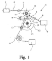
- Fig. 1 shows a drive arrangement for adjustable functional elements in a motor vehicle.
- Functional elements that are adjustable so far have been exemplified in the introduction to the description of the present patent application. Reference may be made to the statements there.
- a flexible traction means 1 and only schematically indicated drive motor 2 for the motorized adjustment of the flexible traction means 1.
- the traction means 1 acting in the direction of traction means 1 driving force is transferable.
- the traction means 1 is drivingly with a first adjustable functional element 3, which is also indicated only schematically coupled or coupled and this first functional element 3 is adjustable by the transmitted via the traction means 1 driving force.
- the drive motor 2 is regularly an electric drive motor, but it can also be a hydraulic motor o. The like.
- the flexible traction means 1 is regularly a rope, a chain, a belt, a belt o. The like., In particular to the soul of a Bowden cable 4, which is located in Fig. 1.
- a pulling on the traction means 1 by means of the drive motor 2 in FIG. 1 to the left has a corresponding pulling on the first functional element 3 in FIG. 1 to the left.
- a corresponding lever can then be moved or a corresponding adjustment, for example a sliding door or a tailgate of a motor vehicle, can take place.
- an adjustable deflection device 5 is provided for the traction means 1 and the traction means 1 is guided over the deflection device 5, that the deflection device 5, preferably in a certain functional position of the drive assembly, by the traction means 1 is adjustable in that the deflection device 5 is coupled to a second adjustable functional element 6 and an adjustment of the deflection device 5 causes an adjustment of the second functional element 6.
- the transmission of the drive force from the drive motor 2 via the traction means 1 causes in the possibly provided, certain functional position of the drive assembly, a resultant force on the deflection device 5, by which the deflection device 5 and with it the second functional element 6 is adjusted.
- the second functional element 6 is coupled to the deflecting device 5 by means of a force transmission element 7, embodied as the core of a Bowden cable 8 in the illustrated exemplary embodiment.
- the second functional element 6 is, as already explained in the introduction to another, usually adjustable over a shorter path functional element, such as a catch of a motor vehicle lock (Zuzieh Vietnamese), an adjustable closing wedge (Zuzieh bamboo) a pawl or a pawl lever of a motor vehicle lock ( Opening drive), or in a motorized seat adjustment, for example, a headrest adjustment.
- Fig. 2 makes it clear in comparison with Fig. 1 that the deflection device 5 in the specific functional position of the drive assembly adjustable, but otherwise is not adjustable.
- a clutch motor 9 is provided for the motor release or blocking the deflection device 5.
- the clutch motor 9 has a much lower power than the drive motor 2. This has already been explained in the general part of the description.
- the clutch motor 9 is required only for the coupling and decoupling and can work with low power.
- the actual drive power is provided by the correspondingly dimensioned drive motor 2, both with regard to the first functional element 3 and with regard to the second functional element 6.
- the deflection device 5 has a deflection roller 10 for the deflection of the pulling means 1 and two tensioning means sections 1a, 1b of the pulling means 1 originate from the deflection roller 10.
- the illustrated embodiment also shows that the deflection device 5 here next to the guide roller 10, which is movable, a further guide roller 11 which is not movably mounted has.
- the traction means 1, the deflection device 5 through a certain Z-shaped, so that the course direction of the traction means 1 total of the drive motor 2 to the first functional element 3 does not change.
- the second guide roller 11 could also be omitted, so that only a deflection would take place on the first guide roller 10.
- the illustrated and preferred embodiment also shows that the deflection device 5 has a pivotable reversing lever 12 and the guide roller 10 is disposed on the lever 12.
- This power transmission element 7 is coupled in the illustrated embodiment with the reversing lever 12 of the deflection device 5.
- the lever 12 is on a fixed axis 13 pivotally mounted and is blocked in Fig. 1, in Fig. 2, however, released.
- an adjustable coupling element 14 which blocks the adjustment of the reversing lever 12 in the disengaged state (FIG. 1) and releases it in the engaged state (FIG. 2).
- the coupling element 14 is designed here as a worm wheel with a cam-like formation 15, which in the disengaged state is in blocking engagement with the reversing lever 12 (FIG. 1).
- the cam 15 of the coupling element 14 has released the reversing lever 12 (FIG. 2).
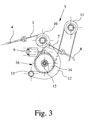
- FIGS. 3 to 5 accordingly shows another variant, which is characterized in that viewed from the drive motor 2, beyond the deflection device 5, a selectively activatable blocking device 16 for the traction means 1 is provided. Instead of the first functional element 3 blocking the traction means 1, the selectively activatable blocking device 16 occurs here.
- the blocking device 16 has been integrated into the deflection device 5, but this need not be so.
- the integration of the blocking device 16 in the deflection device 5 has the advantage that both devices of one and the same additional drive, namely the clutch motor 9 can be operated.
- the blocking device 16 is drivingly engaged with the clutch motor 9 or can be brought, so that the traction means 1 is fixed at released deflection device 5 by the blocking device 16.
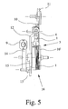
- FIG. 5 shows a view from the left in FIG. 3, that is, when the deflection device 5 is not adjustable.
- the cam 15 of the coupling element 14 is at the bottom and blocks the deflection lever 12.
- the flexible traction device 1 can run unhindered through the deflection device 5.
- the blocking device 16 is released. It can be seen that the pulling means 1 wraps around a brake drum 16 'of the blocking device 16 several times. If the coupling element 14 is moved to the position shown in FIG. 4, in which the deflection device 5 is adjustable, the staple drum 16 'of the blocking device 16 is held in the illustrated embodiment at the same time. Characterized the traction means 1 is blocked and the guide roller 10 on the lever 12 can be adjusted from the position shown in Fig. 3 in the position shown in Fig. 4.
- Both embodiments are particularly suitable for an embodiment in which it is provided that the traction means by the drive motor in the direction of traction means in both, opposite directions is adjustable, in particular to adjust the first adjustable functional element in both directions.
- the first embodiment relates in particular to a sliding door or a tailgate as the first functional element 3 and a closing aid as a second functional element 6.
- the second embodiment relates without stop on the first functional element 3 z.
- the closing aid could also be a pawl drive in the sense of an opening aid as a second functional element 6 realized.
- the deflection lever 12 of the deflection device 5 is coupled to a spring arrangement 24 for its pretension. Possibly.
- a stop for the reversing lever 12 may be provided, on which the reversing lever 12 rests in the non-adjusted state.
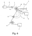
- the drive arrangement shown in Fig. 6 corresponds to its essential structure forth of the drive arrangement shown in Fig. 1, wherein the components clutch motor 9 and coupling element 14 has been omitted. Another, certain functional position of the drive assembly in the above sense is not realized in the drive arrangement shown in Fig. 6.
- the bias of the deflection device 5 is now designed such that during the motorized adjustment of the first functional element 3, the bias normally outweighs, so that the deflection device 5 remains in the non-adjusted state. Thus, first of all the motorized adjustment of the first functional element 3 is secured.
- normal case it is meant that the adjustment of the first functional element 3 is not hindered by objects or persons lying in the adjustment path. If this results in a blocking of the adjustment movement, with a suitable design of the bias of the deflection 5, here the lever 12 in Fig. 6 on the left, adjusted.
- This adjustment can be used to capture the blocking case control technology.
- a microswitch is arranged on the reversing lever 12 for this purpose.
- the bias of the deflection 5 is designed so that at the end of the adjustment of the first functional element 3, the driving force of the drive motor 2 via the traction means 1 causes a resultant force on the deflection 5, the Pretension of the deflector 5 predominates and by the deflection device 5 and with it the second functional element 6 is adjusted.
- the second functional element 6 is therefore adjusted only after a predetermined increase in the transmitted over the traction means 1 driving force. As a result, a sequential adjustment of the first functional element 3 and of the second functional element 6 can be achieved without the necessity of any control measures.
- first functional element 3 is a door, preferably a sliding door, a cover or a flap, preferably a tailgate, of the motor vehicle.
- the second functional element 6 is then preferably realized as a closing element.
- the Zuziehelement can be associated with a motor vehicle lock, the closing aid then usually goes back to the motorized adjustment of the catch of the motor vehicle lock.
- the Zuziehelement can also be associated with an adjustable striker, which corresponds to the motor vehicle lock.
- the Zuziehelement interacts directly with the first functional element, ie with the door, the lid or the flap.
- the closing element of the lever 12 of the deflection device 5 is itself, and in turn interacts directly with the door, the lid or the flap.
- the closing element of the lever 12 of the deflection device 5 is itself, and in turn interacts directly with the door, the lid or the flap.
- the lid or the flap in the closing direction predominates in this preferred embodiment normally the bias of the deflection device 5, so that the deflection device 5 remains in the non-adjusted state. This is shown in FIG.
- the present invention is not limited to the drive of only two functional elements 3, 6.
- a first functional element 3 is a door, a lid or a flap
- a second functional element 6 is a Zuziehelement
- a third functional element is a pawl or a pawl lever of a motor vehicle lock.
- the deflection device 5 is coupled both to the second functional element 6 and to the third functional element.
- the deflection device 5 has a first prestressed deflection lever 12 and a second prestressed deflection lever, to which the second functional element 6 and the third functional element are assigned. With a suitable design, it is thus possible to control the operations of the opening process and closing completely mechanically.
- FIG. 7 shows a further exemplary embodiment, which has independent significance.
- FIG. 7 relates to a drive arrangement for an adjustable functional element 20 in a motor vehicle with a flexible traction means 18 and a drive motor 19 for motorized adjustment of the flexible traction means 18, wherein via the traction means 18 acting in the direction of traction means 18 driving force transferable is, wherein the traction means 18 is drivingly coupled or coupled to the adjustable functional element 20 and the functional element 20 is adjustable by the transmitted via the traction means 18 driving force.
- this functional element 20 may be in particular a Zuziehelement a motor vehicle lock (Zuzieh Vietnamese). It may also be another functional element of a lock mechanism of a motor vehicle lock. It is shown that this functional element 20, in particular so the closing element of the motor vehicle lock, as a pivotable one-armed lever, mounted on a pivot axis 20 'is executed.
- the statements made above on the traction means 1 apply in a corresponding manner.
- the traction means 18 may be formed as a rope. It will, like the traction means 1, normally be formed substantially inelastic, preferably made of steel wire or, more preferably, made of plastic.
- the drive motor 19 is also preferably an electric motor here. It is interesting that in the illustrated embodiment, the traction means 18 from the drive motor 19 gearless, in particular directly on a drive shaft 21 of the drive motor 19 is wound. For this purpose, one can concretely provide that the traction means 18 with one end positively or positively connected to the drive shaft 21. Preferably, the traction means 18 is injected, for example, in a firmly connected to the drive shaft 21 receiving part or pressed or otherwise secured thereto.
- the receiving part may preferably be formed flange-like and form an axial stop for winding the traction means 18 on the drive shaft 21.
- the drive shaft 21 preferably represents a sufficiently long engine shaft of the drive motor 19 is formed. However, it may be in the drive shaft 21 also act to a prolonged or additional shaft portion, which is flanged to the actual motor shaft in the drive motor 19 or connected directly to this in any other way.
- the drive shaft 21 can also be driven by the drive motor 19 via an unillustrated transmission.
- the transmission is preferably integrated into the drive motor 19 or flanged directly to it. Preferably, it is then a geared motor.
- the system is preferably designed such that the traction means 18 helically and / or only single-layer on the drive shaft 21 can be wound. This is achieved, in particular, by virtue of the fact that the traction means 18 is offset or guided correspondingly laterally as a function of a pivoting position of the functional element 20 during the winding-up process. Thus, a minimum wear of the traction means 18 and a precise, repeatable positioning behavior of the drive train formed is made possible.
- a winding stop so arranged on the drive shaft 21 to the receiving part, that between the receiving part and the winding stop the traction means 18 can be wound onto the drive shaft 21.
- the winding stop is formed flange.
- the illustrated and preferred embodiment shows that here the traction means 18 can be wound up against spring force, here and according to a preferred embodiment against the force of a return spring 22 of the functional element 20, which is in particular a Zuziehelement here.
- This return spring 22 is shown schematically in Fig. 7. It is envisaged that when switching off the drive motor 19, the traction means 18 under the action of the spring force of the return spring 22 again unwound and stretched and tightened.
- the drive arrangement has at least one deflection roller for the traction means 18 to form a pulley-type reduction.
- the traction means 18 may also be guided on the functional element 20 around a deflection roller serving as a "loose roller”. With another or free end can then be the traction means 18 is mounted at a fixed point. This is done on a correspondingly designed bearing block o. The like., To allow easy installation. Depending on the geometric arrangement of the components to one another results in a suitable reduction ratio.
- the reduction gear 23 is preferably formed such that it underpins the Aufwikkeltouch of the drive motor 19.
- the reduction gear 23 is quasi a transmission for the traction means 18.
- the reduction gear 23 has a first motor-side take-up area 23a and a second take-up-side take-up area 23b.
- the Aufwickel Societye 23 a, 23 b are preferably arranged at least substantially coaxially and in particular firmly connected to each other.
- the reduction gear 23 is integrally formed, preferably molded from plastic.
- the radius of the first take-up area 23a is, in particular at least by a factor of 2, greater than the radius of the second take-up area 23b.
- the effective winding radius of the first winding region 23a varies. This variation, in particular decrease or increase, of the radius of the first take-up area 23a is conducive to a lateral guidance of the pulling means 18, so that the pulling means 18 is wound on the drive shaft 21 only in a helical or single-layered manner.
- the reduction can be varied, e.g. B. so that initially a large reduction - in particular to overcome large holding or adhesive forces - and then an increasingly smaller reduction - in terms of rapid driving - is realized.
- first part of the traction means 18 extending from the drive shaft 21 to the first winding region 23a and the second part of the traction means 18 extending from the second winding region 23b to the functional element 20 may originate from one and the same traction means 18 ;
- the first and second part of the traction means 18 may thus consist of different pieces and / or of different material and / or have different dimensions, for example due to their different tensile load. But it can be made of a single Switzerlandstoff Federation, in particular piece of rope, both parts of the pulling means 18.
- the free end of the second part of the traction mechanism 18 is preferably attached to the functional element 20 in a form-fitting manner and / or by means of a preferably lockable insert. In particular, the insert is molded directly onto the traction means 18.
- the traction means 18 may be formed from a piece of material which is inserted directly into an injection mold, so that at the same time a receiving part, the reduction gear 23 and an insert are molded onto the traction means 18 and thereby produced. At the same time a positive connection between the traction means 18 and the connection components is made in this case. If necessary, the traction means 18 can be provided with a knot or the like, in particular in the region of the reduction gear 23 and / or at its free ends, in order to ensure a secure form-locking connection there.
- the individual components are preferably initially connected to each other via a holding web after their production, in such a way that the traction means 18 is held somewhat straight. This facilitates storage and handling until assembly, so that an unwanted twisting or tangling of the traction means 18 is prevented. During assembly, the web can then be released from the components of the Buchstoffan extract while the traction means 18 is installed with the components at the desired location.
- the transmission technology explained with reference to FIG. 7 can also be used for the force transmission element 7 for the second functional element 6 by means of the traction means 18, in which case the deflection device replaces the drive motor 19 5, in particular the reversing lever 12 of the deflection 5 occurs and a direct winding on the drive shaft 21 is omitted.
Landscapes
- Power-Operated Mechanisms For Wings (AREA)
- Connection Of Motors, Electrical Generators, Mechanical Devices, And The Like (AREA)
Applications Claiming Priority (1)
| Application Number | Priority Date | Filing Date | Title |
|---|---|---|---|
| DE202005008151U DE202005008151U1 (de) | 2005-03-10 | 2005-03-10 | Antriebsanordnung für verstellbare Funktionselemente in einem Kraftfahrzeug |
Publications (2)
| Publication Number | Publication Date |
|---|---|
| EP1700989A2 true EP1700989A2 (fr) | 2006-09-13 |
| EP1700989A3 EP1700989A3 (fr) | 2012-06-27 |
Family
ID=36617091
Family Applications (1)
| Application Number | Title | Priority Date | Filing Date |
|---|---|---|---|
| EP06004939A Withdrawn EP1700989A3 (fr) | 2005-03-10 | 2006-03-10 | Entraînement pour éléments fonctionnels mobiles dans un véhicule automobile |
Country Status (2)
| Country | Link |
|---|---|
| EP (1) | EP1700989A3 (fr) |
| DE (1) | DE202005008151U1 (fr) |
Cited By (6)
| Publication number | Priority date | Publication date | Assignee | Title |
|---|---|---|---|---|
| US10005498B2 (en) | 2015-09-29 | 2018-06-26 | Brose Schliesssysteme Gmbh & Co. Kommanditgesellschaft | Hatch actuation unit of a motor vehicle |
| WO2019106184A1 (fr) * | 2017-12-01 | 2019-06-06 | Brose Schliesssysteme Gmbh & Co. Kommanditgesellschaft | Agencement de trappe d'un véhicule à moteur |
| CN110139968A (zh) * | 2016-11-07 | 2019-08-16 | 开开特股份公司 | 机动车锁 |
| US20200318400A1 (en) * | 2019-04-02 | 2020-10-08 | Magna BOCO GmbH | Power actuator having cam-driven dual cable actuation mechanism for use with vehicular closure latch assembly |
| US11078689B2 (en) | 2017-11-10 | 2021-08-03 | Brose Schliesssysteme Gmbh & Co. Kg | Motor vehicle lock |
| DE102021128096A1 (de) | 2021-10-28 | 2023-05-04 | Kiekert Aktiengesellschaft | Zuzieheinrichtung für ein Kraftfahrzeug-Schloss |
Families Citing this family (12)
| Publication number | Priority date | Publication date | Assignee | Title |
|---|---|---|---|---|
| DE202007000733U1 (de) * | 2007-01-12 | 2008-05-21 | BROSE SCHLIEßSYSTEME GMBH & CO. KG | Kraftfahrzeugschloß |
| DE102008012434A1 (de) * | 2008-02-29 | 2009-09-03 | Brose Fahrzeugteile Gmbh & Co. Kommanditgesellschaft, Hallstadt | Modulbaugruppe zum Einbau in ein Kraftfahrzeug |
| DE102010063952A1 (de) * | 2010-12-22 | 2012-06-28 | Robert Bosch Gmbh | Antrieb zur Verstellung eines verstellbaren Elements eines Kraftfahrzeugs |
| DE102011002542A1 (de) * | 2011-01-12 | 2012-07-12 | Zf Friedrichshafen Ag | Antriebseinrichtung für einen Fensterheber |
| DE102013001469A1 (de) * | 2012-11-28 | 2014-05-28 | Volkswagen Aktiengesellschaft | Betätigungseinrichtung zur Betätigung eines Verriegelungsmechanismus an einem Fahrzeug |
| DE102013105811A1 (de) | 2013-06-05 | 2014-12-11 | Kiekert Aktiengesellschaft | Betätigungselement für kraftfahrzeugtechnische Anwendungen |
| DE102015107449A1 (de) * | 2015-05-12 | 2016-11-17 | BROSE SCHLIEßSYSTEME GMBH & CO. KG | Schließhilfsanordnung |
| DE102015108254A1 (de) | 2015-05-26 | 2016-12-01 | BROSE SCHLIEßSYSTEME GMBH & CO. KG | Komponente eines Kraftfahrzeugschließsystems |
| DE102016121189A1 (de) * | 2016-11-07 | 2018-05-09 | Kiekert Ag | Betätigungseinrichtung für automatische Anwendungen |
| DE102016121190A1 (de) * | 2016-11-07 | 2018-05-09 | Kiekert Ag | Kraftfahrzeugschloss |
| TWI749898B (zh) * | 2020-11-24 | 2021-12-11 | 誼騰動力股份有限公司 | 電動鎖具 |
| DE102024122972A1 (de) * | 2024-08-12 | 2026-02-12 | Kiekert Aktiengesellschaft | Kraftfahrzeug-Schloss |
Citations (3)
| Publication number | Priority date | Publication date | Assignee | Title |
|---|---|---|---|---|
| US4998049A (en) | 1989-01-26 | 1991-03-05 | General Motors Corporation | Control apparatus having a remote abort function |
| DE4427213C2 (de) | 1993-07-30 | 2000-09-21 | Ohi Seisakusho Co Ltd | Türschloss für ein Kraftfahrzeug |
| DE10356306A1 (de) | 2003-11-28 | 2005-06-23 | Brose Schließsysteme GmbH & Co.KG | Kraftfahrzeugschloß |
Family Cites Families (7)
| Publication number | Priority date | Publication date | Assignee | Title |
|---|---|---|---|---|
| DE3907632A1 (de) * | 1989-03-09 | 1990-09-20 | Bayerische Motoren Werke Ag | Schloss mit sicherungseinrichtung, insbesondere fuer fahrzeugtueren |
| US5549337A (en) * | 1994-10-07 | 1996-08-27 | Thomas Loeff | Motor actuated latch mechanism |
| DE19604724A1 (de) * | 1996-02-09 | 1997-08-14 | Vdo Schindling | Schloß, insbesondere für Kraftfahrzeugtüren |
| FR2775717B1 (fr) * | 1998-03-03 | 2000-05-05 | Valeo Systemes De Fermetures | Dispositif d'ouverture/fermeture d'un ouvrant, notamment pour vehicule automobile |
| DE10064914B4 (de) * | 2000-12-23 | 2005-06-02 | Siemens Ag | Türschloß mit Zuziehhilfe |
| DE10100154A1 (de) * | 2001-01-03 | 2002-07-18 | Siemens Ag | Kraftübertragung mit Überlastschutz |
| DE102004009874A1 (de) * | 2004-02-26 | 2005-09-15 | Brose Fahrzeugteile Gmbh & Co. Kg, Coburg | Vorrichtung zum Verstellen verstellbarer Bauteile einer Kraftfahrzeugtür |
-
2005
- 2005-03-10 DE DE202005008151U patent/DE202005008151U1/de not_active Expired - Lifetime
-
2006
- 2006-03-10 EP EP06004939A patent/EP1700989A3/fr not_active Withdrawn
Patent Citations (3)
| Publication number | Priority date | Publication date | Assignee | Title |
|---|---|---|---|---|
| US4998049A (en) | 1989-01-26 | 1991-03-05 | General Motors Corporation | Control apparatus having a remote abort function |
| DE4427213C2 (de) | 1993-07-30 | 2000-09-21 | Ohi Seisakusho Co Ltd | Türschloss für ein Kraftfahrzeug |
| DE10356306A1 (de) | 2003-11-28 | 2005-06-23 | Brose Schließsysteme GmbH & Co.KG | Kraftfahrzeugschloß |
Cited By (10)
| Publication number | Priority date | Publication date | Assignee | Title |
|---|---|---|---|---|
| US10005498B2 (en) | 2015-09-29 | 2018-06-26 | Brose Schliesssysteme Gmbh & Co. Kommanditgesellschaft | Hatch actuation unit of a motor vehicle |
| CN110139968A (zh) * | 2016-11-07 | 2019-08-16 | 开开特股份公司 | 机动车锁 |
| US11078689B2 (en) | 2017-11-10 | 2021-08-03 | Brose Schliesssysteme Gmbh & Co. Kg | Motor vehicle lock |
| WO2019106184A1 (fr) * | 2017-12-01 | 2019-06-06 | Brose Schliesssysteme Gmbh & Co. Kommanditgesellschaft | Agencement de trappe d'un véhicule à moteur |
| US10801236B2 (en) | 2017-12-01 | 2020-10-13 | Brose Schilesssysteme GmbH & Co. Kommanditgesellschaft | Hatch arrangement of a motor vehicle |
| US11572718B2 (en) | 2017-12-01 | 2023-02-07 | Brose Schließsysteme GmbH & Co. Kommanditgesellschaft, Wuppertal | Hatch arrangement of a motor vehicle |
| US20200318400A1 (en) * | 2019-04-02 | 2020-10-08 | Magna BOCO GmbH | Power actuator having cam-driven dual cable actuation mechanism for use with vehicular closure latch assembly |
| US11885159B2 (en) * | 2019-04-02 | 2024-01-30 | Magna Closures Inc. | Power actuator having cam-driven dual cable actuation mechanism for use with vehicular closure latch assembly |
| US20240133218A1 (en) * | 2019-04-02 | 2024-04-25 | Magna BOCO GmbH | Power actuator having cam-driven dual cable actuation mechanism for use with vehicular closure latch assembly |
| DE102021128096A1 (de) | 2021-10-28 | 2023-05-04 | Kiekert Aktiengesellschaft | Zuzieheinrichtung für ein Kraftfahrzeug-Schloss |
Also Published As
| Publication number | Publication date |
|---|---|
| DE202005008151U1 (de) | 2006-07-27 |
| EP1700989A3 (fr) | 2012-06-27 |
Similar Documents
| Publication | Publication Date | Title |
|---|---|---|
| EP1536090B1 (fr) | Serrure pour véhicule | |
| EP1700989A2 (fr) | Entraînement pour éléments fonctionnels mobiles dans un véhicule automobile | |
| EP1389544B1 (fr) | Store à enrouleur avec un méchanisme d' accouplement | |
| WO2016074842A1 (fr) | Serrure de véhicule automobile | |
| DE10041498B4 (de) | Schließeinrichtung für eine Fahrzeugtür | |
| EP3899179B1 (fr) | Dispositif d'installation pour une porte de véhicule automobile | |
| WO2022063357A1 (fr) | Dispositif d'ouverture pour un élément de portière de véhicule automobile | |
| DE202005019198U1 (de) | Kraftfahrzeugschloß | |
| DE102017101703A1 (de) | Schloss mit Zuzieheinrichtung für ein Kraftfahrzeug | |
| EP1724423B1 (fr) | Serrure de véhicule automobile et dispositif de retenue pour un dispositif de sécurité d'un véhicule | |
| EP1760239A2 (fr) | Dispositif et procédé d'actionnement d'une pièce de carrosserie de véhicule automobile | |
| DE102007046916A1 (de) | Kraftfahrzeugschloß | |
| DE102006011083A1 (de) | Kraftfahrzeugschloß | |
| DE102008012434A1 (de) | Modulbaugruppe zum Einbau in ein Kraftfahrzeug | |
| DE102021118274A1 (de) | Kraftfahrzeugschloss | |
| DE10206161A1 (de) | Öffnungsfähiges Fahrzeugdach mit mindestens einem Deckel und zwei Abdeckeinrichtungen | |
| DE10362364B3 (de) | Kraftfahrzeugschloss | |
| EP1932987B1 (fr) | Agencement d'élément de commande dans un véhicule automobile | |
| DE102024122703A1 (de) | Kraftfahrzeugschlossanordnung für ein Verschlusselement eines Kraftfahrzeugs | |
| DE10148041B4 (de) | Kraftfahrzeugtürschloss-Baueinheit | |
| DE102007030139A1 (de) | Verstellantrieb zur Bewegung eines Funktionselementes in oder an einer Kraftfahrzeugkarosserie | |
| DE102024129328A1 (de) | Kraftfahrzeugschlossanordnung für ein Verschlusselement eines Kraftfahrzeugs | |
| WO2025256991A1 (fr) | Verrou de véhicule à moteur pour élément de fermeture de véhicule à moteur | |
| EP4656831A1 (fr) | Dispositif pour recevoir et libérer un moyen de traction de type câble | |
| DE202005004042U1 (de) | Kraftfahrzeugschloß |
Legal Events
| Date | Code | Title | Description |
|---|---|---|---|
| PUAI | Public reference made under article 153(3) epc to a published international application that has entered the european phase |
Free format text: ORIGINAL CODE: 0009012 |
|
| AK | Designated contracting states |
Kind code of ref document: A2 Designated state(s): AT BE BG CH CY CZ DE DK EE ES FI FR GB GR HU IE IS IT LI LT LU LV MC NL PL PT RO SE SI SK TR |
|
| AX | Request for extension of the european patent |
Extension state: AL BA HR MK YU |
|
| RIN1 | Information on inventor provided before grant (corrected) |
Inventor name: STRACK, KLAUS Inventor name: DREIMANN, THOMAS PETER Inventor name: REINERT, JOERG Inventor name: STAFANIC, JOSIP Inventor name: LANGFERMANN, MICHAEL Inventor name: KACHOUH, CHECRALLAH Inventor name: STANIC, IVICA |
|
| PUAL | Search report despatched |
Free format text: ORIGINAL CODE: 0009013 |
|
| AK | Designated contracting states |
Kind code of ref document: A3 Designated state(s): AT BE BG CH CY CZ DE DK EE ES FI FR GB GR HU IE IS IT LI LT LU LV MC NL PL PT RO SE SI SK TR |
|
| AX | Request for extension of the european patent |
Extension state: AL BA HR MK YU |
|
| RIC1 | Information provided on ipc code assigned before grant |
Ipc: E05F 15/10 20060101ALI20120518BHEP Ipc: E05F 15/14 20060101AFI20120518BHEP Ipc: E05F 11/48 20060101ALI20120518BHEP |
|
| AKY | No designation fees paid | ||
| REG | Reference to a national code |
Ref country code: DE Ref legal event code: R108 Effective date: 20130306 |
|
| STAA | Information on the status of an ep patent application or granted ep patent |
Free format text: STATUS: THE APPLICATION IS DEEMED TO BE WITHDRAWN |
|
| 18D | Application deemed to be withdrawn |
Effective date: 20130103 |