EP1700996A2 - Enrouleur de sangle pour un dispositif d'occultation comme un volet roulant - Google Patents
Enrouleur de sangle pour un dispositif d'occultation comme un volet roulant Download PDFInfo
- Publication number
- EP1700996A2 EP1700996A2 EP06002040A EP06002040A EP1700996A2 EP 1700996 A2 EP1700996 A2 EP 1700996A2 EP 06002040 A EP06002040 A EP 06002040A EP 06002040 A EP06002040 A EP 06002040A EP 1700996 A2 EP1700996 A2 EP 1700996A2
- Authority
- EP
- European Patent Office
- Prior art keywords
- antenna
- gurtwickler
- housing
- pivot axis
- module
- Prior art date
- Legal status (The legal status is an assumption and is not a legal conclusion. Google has not performed a legal analysis and makes no representation as to the accuracy of the status listed.)
- Granted
Links
- 229910000859 α-Fe Inorganic materials 0.000 claims abstract description 7
- 238000003780 insertion Methods 0.000 claims description 3
- 230000037431 insertion Effects 0.000 claims description 3
- 238000004804 winding Methods 0.000 claims description 2
- 230000005540 biological transmission Effects 0.000 description 3
- 238000009434 installation Methods 0.000 description 2
- 238000009420 retrofitting Methods 0.000 description 2
- 230000008901 benefit Effects 0.000 description 1
- 238000010276 construction Methods 0.000 description 1
- 230000008878 coupling Effects 0.000 description 1
- 238000010168 coupling process Methods 0.000 description 1
- 238000005859 coupling reaction Methods 0.000 description 1
- 230000001419 dependent effect Effects 0.000 description 1
- 238000001514 detection method Methods 0.000 description 1
- 230000000694 effects Effects 0.000 description 1
- 238000000034 method Methods 0.000 description 1
- 238000005457 optimization Methods 0.000 description 1
- 230000008569 process Effects 0.000 description 1
- 230000009467 reduction Effects 0.000 description 1
- 230000002787 reinforcement Effects 0.000 description 1
Images


Classifications
-
- H—ELECTRICITY
- H01—ELECTRIC ELEMENTS
- H01Q—ANTENNAS, i.e. RADIO AERIALS
- H01Q3/00—Arrangements for changing or varying the orientation or the shape of the directional pattern of the waves radiated from an antenna or antenna system
- H01Q3/02—Arrangements for changing or varying the orientation or the shape of the directional pattern of the waves radiated from an antenna or antenna system using mechanical movement of antenna or antenna system as a whole
- H01Q3/04—Arrangements for changing or varying the orientation or the shape of the directional pattern of the waves radiated from an antenna or antenna system using mechanical movement of antenna or antenna system as a whole for varying one co-ordinate of the orientation
-
- E—FIXED CONSTRUCTIONS
- E06—DOORS, WINDOWS, SHUTTERS, OR ROLLER BLINDS IN GENERAL; LADDERS
- E06B—FIXED OR MOVABLE CLOSURES FOR OPENINGS IN BUILDINGS, VEHICLES, FENCES OR LIKE ENCLOSURES IN GENERAL, e.g. DOORS, WINDOWS, BLINDS, GATES
- E06B9/00—Screening or protective devices for wall or similar openings, with or without operating or securing mechanisms; Closures of similar construction
- E06B9/56—Operating, guiding or securing devices or arrangements for roll-type closures; Spring drums; Tape drums; Counterweighting arrangements therefor
- E06B9/78—Operating, guiding or securing devices or arrangements for roll-type closures; Spring drums; Tape drums; Counterweighting arrangements therefor for direct manual operation, e.g. by tassels, by handles
-
- H—ELECTRICITY
- H01—ELECTRIC ELEMENTS
- H01Q—ANTENNAS, i.e. RADIO AERIALS
- H01Q1/00—Details of, or arrangements associated with, antennas
- H01Q1/12—Supports; Mounting means
- H01Q1/22—Supports; Mounting means by structural association with other equipment or articles
-
- H—ELECTRICITY
- H01—ELECTRIC ELEMENTS
- H01Q—ANTENNAS, i.e. RADIO AERIALS
- H01Q3/00—Arrangements for changing or varying the orientation or the shape of the directional pattern of the waves radiated from an antenna or antenna system
- H01Q3/02—Arrangements for changing or varying the orientation or the shape of the directional pattern of the waves radiated from an antenna or antenna system using mechanical movement of antenna or antenna system as a whole
-
- E—FIXED CONSTRUCTIONS
- E06—DOORS, WINDOWS, SHUTTERS, OR ROLLER BLINDS IN GENERAL; LADDERS
- E06B—FIXED OR MOVABLE CLOSURES FOR OPENINGS IN BUILDINGS, VEHICLES, FENCES OR LIKE ENCLOSURES IN GENERAL, e.g. DOORS, WINDOWS, BLINDS, GATES
- E06B9/00—Screening or protective devices for wall or similar openings, with or without operating or securing mechanisms; Closures of similar construction
- E06B9/56—Operating, guiding or securing devices or arrangements for roll-type closures; Spring drums; Tape drums; Counterweighting arrangements therefor
- E06B9/78—Operating, guiding or securing devices or arrangements for roll-type closures; Spring drums; Tape drums; Counterweighting arrangements therefor for direct manual operation, e.g. by tassels, by handles
- E06B2009/785—Operating, guiding or securing devices or arrangements for roll-type closures; Spring drums; Tape drums; Counterweighting arrangements therefor for direct manual operation, e.g. by tassels, by handles by belts, straps, bands, tapes, cords, tassels
Definitions
- the invention relates to a belt winder for a dimming device such as a roller shutter according to the preamble of claim 1.
- the motor-operated belt winder in question is widely used for retrofitting, i. H.
- For the exchange of manually operated Gurtwickler this is provided in a first variant of the installation of the motor-operated Gurtwicklers in an existing belt box.
- Auiputztechnik known that are possibly designed as a swivel.
- Gurtwickler Motorized Gurtwickler are now increasingly equipped with automatic functions.
- One of these automatic functions is that the Gurtwickler is automatically operated at predetermined times.
- the Gurtwickler is equipped with a time module.
- the known Gurtwickler (DE 10 2004 012 354 A1), from which the invention proceeds, has a drive arrangement and a control arrangement, wherein the control arrangement has a configured as Funkuhmiodul time module.
- the radio clock module of the known Gurtwicklers is adapted to receive one of the above long-wave time signals to determine the current time via radio.
- an antenna is provided which is regularly configured as a ferrite antenna.
- the disadvantage of the above application of a ferrite antenna is their high directivity, so that in unfavorable installation position of Gurtwicklers the reception of the time signal is of poor quality. In the worst case, this leads to the reception of a faulty time signal and as a result to the determination of a faulty current time.
- the remote control device has a time module configured as a radio clock module and transmits the corresponding time information by radio to the stationary belt winder or the stationary belt winder. Due to the mobility of the remote control device, it is readily possible to ensure optimum reception of the time signal. However, a disadvantage is the additional implementation effort, especially if a remote control device, for example, for cost reasons, is not desired.
- the invention is based on the problem of designing the known Gurtwickler and further educate, that the reliability is increased in terms of the proper operation of the time module.
- the antenna of the time module is arranged so adjustable over a holding device that alignment of the antenna to optimize the reception of the time signal is possible.
- adjustable is meant here that the antenna can perform a relative movement relative to the Gurtwickler in the rest. This ensures that even with a fixed Gurtwickler optimal alignment of the antenna is ensured.
- the time module may be configured as a self-contained unit, which may be completely interchangeable as a module against another module, but it may also consist of several separate units. Furthermore, it can be provided that the time module comprises the antenna, or that the time module, the antenna, if necessary, in turn, is assigned as a separate unit,
- the antenna is preferably a ferrite antenna, since this allows a particularly compact construction. But there are also other embodiments for the antenna conceivable.
- a particularly advantageous alignment behavior can be achieved according to claim 5 characterized in that the antenna is pivotable about a pivot axis.
- the pivoting about a single pivot axis or two preferably mutually perpendicularly oriented pivot axes (claim 7) is conceivable.
- the preferred embodiments according to claim 8 allow the alignment of the antenna with minimal effort.
- Essential here is the fact that the alignment is not associated with a complex disassembly process.
- Aligning the antenna is particularly convenient for the user when information about the respective current reception level of the time signal is visible during the alignment of the antenna via a display on Gurtwickler (claim 12). As a result, in particular, the time required for aligning the antenna can be significantly reduced.
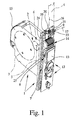
- the Gurtwickler shown in the drawing is intended for a darkening device such as a blind, a blind, an awning o.
- the Gurtwickler is equipped with a housing 1 and with a drive assembly 2 located in the housing 1.
- the housing 1 it must not necessarily to act a completely closed housing 1.
- the term "housing” also includes a frame which accommodates the drive arrangement 2.
- the drive assembly 2 preferably has a reel 3 for winding a webbing 4, an electric drive motor 5 and a reduction gear 6 coupling to the reel 3. These components of the drive assembly 2 are merely indicated in the drawing. With regard to a preferred embodiment of the drive assembly 2 may be made to the German Utility Model 297 22 936.2 of the Applicant. The content of this utility model is in this respect made to the full extent the subject of the present application.
- the Gurtwickler is equipped with a control assembly 7, which is arranged in the illustrated and so far preferred embodiment in the housing 1. But it can also be provided that the control arrangement 7 is arranged on the housing 1. This is the case, for example, if the control arrangement 7 is constructed in a plurality of modules which can each be plugged onto the housing 1.
- the control arrangement 7 has a time module 8, which is designed as a radio clock module.
- the time module 8 is a DCF module.
- a time signal for determining the current time can be received via radio.
- the time module 8 is associated with an antenna 9 for receiving the time signal.
- the antenna 9 can also be an integral part of the time module 9.
- the antenna 9 is preferably designed as a ferrite antenna. This is also the case with the illustrated preferred embodiment.
- the antenna 9 of the time module 8 is arranged so adjustable about a holding device 10 that an alignment of the antenna 9 to Optimization of the reception of the time signal is possible. This can be seen from a synopsis of FIGS. 1 and 3 and will be explained in more detail below,
- Ausrhmngs form the housing 1 in the installed state, at least in most cases arranged in a masonry recess.
- Belt winder of this type are often employed in retrofitting existing dimming devices to replace existing mechanical winder.
- the main advantage of such a Gurtwicklers with electric motor is that it readily substitutes in the most standardized masonry recess for the purely mechanical Gurtwickler place. The exchange is very easy.
- the Gurtwickler but also be designed as a surface-mounted device. Such Gurtwickler be used accordingly when a masonry recess is not available or, for example, for reasons of cost, should not be provided.
- a Gurtwicklers designed as a radio clock module time module 8
- the antenna 9 forcibly disposed in close proximity to the masonry.
- the antenna 9 in the proposed Gurtwickler can be aligned. Without aligning the antenna 9, reliable reception of the timing signal can not be ensured.
- the housing 1 has a front panel 11, the various control elements 12, a display 13 and an insertion channel 14 for the webbing 4 borders.
- the front panel 11 receives said elements 12, 13, 14.
- the controls 12 may be arranged on the front panel 11.
- the housing 1 thus has in any case a base body 15 and the above front panel 11. It may also be that the housing 1 consists of a plurality of further subcomponents.
- the antenna 9 is arranged in the housing 1. Particularly advantageous is the arrangement of the antenna 9 directly under the front panel 11, so that as few structural components of Gurtwicklers interfere with the reception of the time signal. In the illustrated preferred embodiment, it is further such that the antenna 9 is arranged in the region of the insertion channel 14 for the webbing 4. This is advantageous in that the antenna 9 is then located at a considerable distance from the drive arrangement 2 and its components disturbing or shielding the reception.
- the antenna 9 is pivotally adjustable about a pivot axis 16.
- the pivoting angle of the antenna 9 achievable with this is essentially dependent on the configuration of the housing 1. In the exemplary embodiment shown, the pivoting angle of the antenna 9 is approximately 12 °.
- the antenna 9 in the embodiment of the antenna 9 as a ferrite antenna, it is preferably such that the antenna 9 extends in the direction of a longitudinal axis 17, wherein the pivot axis 16 of the antenna 9 preferably extends perpendicular to the longitudinal axis 17 of the antenna 9.
- the pivot axis 16 of the antenna 9 extends in the installed state substantially in the vertical direction. This takes account of the fact that, in the orientation, it is primarily based on the fact that the longitudinal axis 17 of the antenna 9 assumes different orientations within a horizontal plane.
- the antenna 9 is pivotable about a further pivot axis, wherein the two pivot axes 16 are preferably aligned perpendicular to each other.
- the orientation of the antenna 9 is particularly easy to carry out insofar as the antenna 9 is adjustable, without the Gurtwickler, in particular the housing 9 or the front panel 11 of the housing 1, to dismantle.
- the housing 1, or the front panel 11, here has a recess 18, through which access to the adjustment of the antenna 9 is possible.
- the engagement profile 19 may also have a simple slot or other shape. This makes it possible, the alignment, so the adjustment of the antenna 9, with a simple tool such as a screwdriver o. The like. To accomplish. But it can also be provided that the holding device 10 is equipped with an actuating element for the adjustment of the antenna 9, whereby the adjustment of the antenna 9 would be possible without tools.
- the holding device 10 now has a stationary bearing element 20 for the pivotable mounting of a holding element 21.
- the holding element 21 is pivotable about the pivot axis 16.
- the holding element 21 is preferably clipped into the bearing element 20.
- the holding element 21 is equipped with a series of resilient hooks 23, which are in the installed state with a circular shoulder of the bearing element 20 in engagement.
- the bearing element 20 and the holding element 21 are engaged with one another via in each case one engagement surface and that the engagement surfaces extend substantially perpendicular to the pivot axis 16 of the holding element 21.
- these engagement surfaces are roughened in each case in order to increase the friction between these two components.
- the two engagement surfaces have mutually corresponding toothings, which in turn counteract the automatic, unwanted adjustment of the antenna 9.
- a further preferred embodiment leads to a particularly convenient alignment of the antenna 9.
- the control device 7 controls the display 13 so that during the alignment of the antenna 9 via the display 13, information about the respective current reception level of the time signal visible is.
- a numerical representation or a graphical representation for example, by a bar with depending on the current reception level changing length o. The like., Possible.
- the antenna 9 is motor-adjustable is particularly user-friendly.
- the control arrangement 7 then automatically adjusts the orientation of the antenna 9.
- the control arrangement 7 has a corresponding control circuit.
- the antenna 9 is adjusted by the control circuit as long as the current reception level of the time signal is maximum.
- the antenna 9 is connected via a connecting line, not shown, with the control arrangement 7 in the rest.
- an electrical connection 24 is provided on the holding device 10, which is connected via the connecting line to a terminal 25 of the control arrangement 7 accordingly.
- the Gurtwickler invention can also be equipped with a Funkfiem Kunststoffung for fenragesteverte triggering individual functions. If, at the same time, as described above, the drive motor 5 is designed as a DC motor (preferably 220 V), then there are special requirements for this radio remote control. In a DC motor, in fact, every time the commutator is reversed, a brush fire occurs which disturbs the radio transmission of the radio remote control.
- a DC motor in fact, every time the commutator is reversed, a brush fire occurs which disturbs the radio transmission of the radio remote control.
- the above disturbance of the radio remote control by the brush fire of the DC motor 5 can be reduced for example by a suitable choice of the frequency range of the radio remote control. But it is also possible to redundantly encode the signals of the radio remote control, so that the transmission is either error-resistant or that transmission errors are detected in any case.
- the radio signal is encoded via frequency modulation.
- the radio remote control is preferably a GFSK transceiver (Gaussian Frequency Shift Keying) with CRC coding (Cylic Redundancy Check) and with Manchester code collision detection.
- the above embodiment of a radio remote control is applicable to all areas of home automation, but in particular to the field of motor Gurtwickler for dimming devices such as a shutter.
Landscapes
- Engineering & Computer Science (AREA)
- Structural Engineering (AREA)
- Architecture (AREA)
- Civil Engineering (AREA)
- Support Of Aerials (AREA)
- Operating, Guiding And Securing Of Roll- Type Closing Members (AREA)
- Electric Clocks (AREA)
- Measuring Pulse, Heart Rate, Blood Pressure Or Blood Flow (AREA)
Applications Claiming Priority (1)
| Application Number | Priority Date | Filing Date | Title |
|---|---|---|---|
| DE200520002747 DE202005002747U1 (de) | 2005-02-18 | 2005-02-18 | Gurtwickler für eine Verdunkelungsvorrichtung wie einen Rollladen |
Publications (3)
| Publication Number | Publication Date |
|---|---|
| EP1700996A2 true EP1700996A2 (fr) | 2006-09-13 |
| EP1700996A3 EP1700996A3 (fr) | 2008-10-29 |
| EP1700996B1 EP1700996B1 (fr) | 2009-09-02 |
Family
ID=34639012
Family Applications (1)
| Application Number | Title | Priority Date | Filing Date |
|---|---|---|---|
| EP06002040A Expired - Lifetime EP1700996B1 (fr) | 2005-02-18 | 2006-02-01 | Enrouleur de sangle pour un dispositif d'occultation comme un volet roulant |
Country Status (3)
| Country | Link |
|---|---|
| EP (1) | EP1700996B1 (fr) |
| AT (1) | ATE441773T1 (fr) |
| DE (2) | DE202005002747U1 (fr) |
Cited By (5)
| Publication number | Priority date | Publication date | Assignee | Title |
|---|---|---|---|---|
| EP1985792A3 (fr) * | 2007-04-25 | 2009-02-18 | ARCA Beteiligungen GmbH | Enrouleur de sangle pour un volet roulant |
| WO2017054083A1 (fr) * | 2015-10-02 | 2017-04-06 | Axis Labs Inc. | Système d'entraînement de moteur externe pour système de couvre-fenêtre à boucle de cordon continu |
| US10863846B2 (en) | 2015-10-02 | 2020-12-15 | Axis Labs Inc. | External motor drive system for window covering system with continuous cord loop |
| US11519221B2 (en) | 2014-11-06 | 2022-12-06 | Ryse Inc. | Motor drive system for window covering system with continuous cord loop |
| US11840886B2 (en) | 2021-05-12 | 2023-12-12 | Ryse Inc. | External motor drive system adjusting for creep in window covering system with continuous cord loop |
Families Citing this family (2)
| Publication number | Priority date | Publication date | Assignee | Title |
|---|---|---|---|---|
| DE202006003524U1 (de) * | 2006-03-04 | 2006-04-27 | Alfred Schellenberg Gmbh | Gurtwickler für das Gurtband o.dgl. Zugelement einer Verdunkelungsvorrichtung, insbesondere eines Rolladens o.dgl. |
| DE202009001375U1 (de) | 2009-02-04 | 2010-06-24 | Arca Beteiligungen Gmbh | Antrieb für die motorische Verstellung einer Verdunkelungsvorrichtung wie eines Rollladens o.dgl. |
Citations (2)
| Publication number | Priority date | Publication date | Assignee | Title |
|---|---|---|---|---|
| DE20001483U1 (de) | 2000-01-28 | 2000-08-17 | Rademacher, Wilhelm, 46414 Rhede | Fernsteuervorrichtung und Verdunkelungsanlage |
| DE102004012354A1 (de) | 2003-03-11 | 2004-09-30 | ECG Elektrocomponent Gründau GmbH | Elektrischer Gurtwickler |
-
2005
- 2005-02-18 DE DE200520002747 patent/DE202005002747U1/de not_active Expired - Lifetime
-
2006
- 2006-02-01 DE DE502006004699T patent/DE502006004699D1/de not_active Expired - Lifetime
- 2006-02-01 EP EP06002040A patent/EP1700996B1/fr not_active Expired - Lifetime
- 2006-02-01 AT AT06002040T patent/ATE441773T1/de active
Patent Citations (2)
| Publication number | Priority date | Publication date | Assignee | Title |
|---|---|---|---|---|
| DE20001483U1 (de) | 2000-01-28 | 2000-08-17 | Rademacher, Wilhelm, 46414 Rhede | Fernsteuervorrichtung und Verdunkelungsanlage |
| DE102004012354A1 (de) | 2003-03-11 | 2004-09-30 | ECG Elektrocomponent Gründau GmbH | Elektrischer Gurtwickler |
Cited By (11)
| Publication number | Priority date | Publication date | Assignee | Title |
|---|---|---|---|---|
| EP1985792A3 (fr) * | 2007-04-25 | 2009-02-18 | ARCA Beteiligungen GmbH | Enrouleur de sangle pour un volet roulant |
| US11519221B2 (en) | 2014-11-06 | 2022-12-06 | Ryse Inc. | Motor drive system for window covering system with continuous cord loop |
| US12098595B2 (en) | 2014-11-06 | 2024-09-24 | Ryse Inc. | Motor drive system for window covering system with continuous cord loop |
| WO2017054083A1 (fr) * | 2015-10-02 | 2017-04-06 | Axis Labs Inc. | Système d'entraînement de moteur externe pour système de couvre-fenêtre à boucle de cordon continu |
| US10104997B2 (en) | 2015-10-02 | 2018-10-23 | Axis Labs Inc. | External motor drive system for window covering system with continuous cord loop |
| US10863846B2 (en) | 2015-10-02 | 2020-12-15 | Axis Labs Inc. | External motor drive system for window covering system with continuous cord loop |
| US11178992B2 (en) | 2015-10-02 | 2021-11-23 | Ryse Inc. | External motor drive system for window covering system with continuous cord loop |
| US11272802B2 (en) | 2015-10-02 | 2022-03-15 | Ryse Inc. | External motor drive system for window covering system with continuous cord loop |
| US11583126B2 (en) | 2015-10-02 | 2023-02-21 | Ryse Inc. | External motor drive system for window covering system with continuous cord loop |
| US11840886B2 (en) | 2021-05-12 | 2023-12-12 | Ryse Inc. | External motor drive system adjusting for creep in window covering system with continuous cord loop |
| US12215546B2 (en) | 2021-05-12 | 2025-02-04 | Ryse Inc. | External motor drive system adjusting for creep in window covering system with continuous cord loop |
Also Published As
| Publication number | Publication date |
|---|---|
| DE202005002747U1 (de) | 2005-06-02 |
| EP1700996A3 (fr) | 2008-10-29 |
| EP1700996B1 (fr) | 2009-09-02 |
| ATE441773T1 (de) | 2009-09-15 |
| DE502006004699D1 (de) | 2009-10-15 |
Similar Documents
| Publication | Publication Date | Title |
|---|---|---|
| EP1455038B1 (fr) | Système de verrouillage, notamment serrure de porte, serrure de fenêtre ou similaire | |
| DE10346654B3 (de) | Griff für ein Fenster oder eine Tür | |
| EP1700996B1 (fr) | Enrouleur de sangle pour un dispositif d'occultation comme un volet roulant | |
| EP3178141A1 (fr) | Adaptateur pour la mise en contact d'un disjoncteur sur un système de barres omnibus | |
| EP1801339B1 (fr) | Entraînement pour actionner un battant mobile, particulièrement pour une porte ou une fenêtre | |
| EP1766743B1 (fr) | Systeme a barres omnibus avec unite de montage formee d'une plaque de base et d'elements de fixation | |
| EP1514001B1 (fr) | Dispositif d'entrainement | |
| EP1091079A2 (fr) | Système de contrôle pour unités d'entraínement à moteur pour un dispositif d'occultation ou d'obscurcissement | |
| EP1132560B1 (fr) | Charnière et procédé de réglage en hauteur d'une charnière | |
| DE102004012354B4 (de) | Elektrischer Gurtwickler | |
| DE102007014170A1 (de) | Optoelektronische Sensoranordnung | |
| DE9403746U1 (de) | Vorrichtung zum Öffnen und Schließen von Toren | |
| EP0168714B1 (fr) | Fixation rapide d'un boîtier d'appareil d'installation électrique sur un rail de support profilé | |
| EP0529316A1 (fr) | Dispositif de contrôle de la température d'un local | |
| DE20119997U1 (de) | Befestigungsvorrichtung | |
| DE3048333C2 (de) | Halterungsvorrichtung für ein Springrollo | |
| EP2216491B1 (fr) | Entraînement pour le réglage motorisé d'un dispositif d'assombrissement tel qu'un store ou analogue | |
| EP1449988B1 (fr) | Module de retenue pour ferrure de fenêtre ou de porte | |
| DE3037405A1 (de) | Elektrisches niederspannungsschaltegeraet | |
| DE3742425A1 (de) | Verfahren und anordnung zum erfassen der funktionszustaende bei einem fernsehgeraet | |
| EP2669457A1 (fr) | Unité de serrure et procédé de montage d'un actionneur de porte sur une plaque de montage d'une unité de serrure | |
| EP1985792A2 (fr) | Enrouleur de sangle pour un volet roulant | |
| DE10301014B4 (de) | Elektronisches Steuergerät | |
| EP1725729B1 (fr) | Systeme de suspension d'une porte coulissante | |
| EP0844356A1 (fr) | Dispositif pour la commande d'une fenêtre |
Legal Events
| Date | Code | Title | Description |
|---|---|---|---|
| PUAI | Public reference made under article 153(3) epc to a published international application that has entered the european phase |
Free format text: ORIGINAL CODE: 0009012 |
|
| AK | Designated contracting states |
Kind code of ref document: A2 Designated state(s): AT BE BG CH CY CZ DE DK EE ES FI FR GB GR HU IE IS IT LI LT LU LV MC NL PL PT RO SE SI SK TR |
|
| AX | Request for extension of the european patent |
Extension state: AL BA HR MK YU |
|
| RAP1 | Party data changed (applicant data changed or rights of an application transferred) |
Owner name: ARCA BETEILIGUNGEN GMBH |
|
| RIN1 | Information on inventor provided before grant (corrected) |
Inventor name: RADEMACHER, WILHELM |
|
| PUAL | Search report despatched |
Free format text: ORIGINAL CODE: 0009013 |
|
| AK | Designated contracting states |
Kind code of ref document: A3 Designated state(s): AT BE BG CH CY CZ DE DK EE ES FI FR GB GR HU IE IS IT LI LT LU LV MC NL PL PT RO SE SI SK TR |
|
| AX | Request for extension of the european patent |
Extension state: AL BA HR MK YU |
|
| 17P | Request for examination filed |
Effective date: 20081126 |
|
| GRAP | Despatch of communication of intention to grant a patent |
Free format text: ORIGINAL CODE: EPIDOSNIGR1 |
|
| AKX | Designation fees paid |
Designated state(s): AT BE BG CH CY CZ DE DK EE ES FI FR GB GR HU IE IS IT LI LT LU LV MC NL PL PT RO SE SI SK TR |
|
| GRAS | Grant fee paid |
Free format text: ORIGINAL CODE: EPIDOSNIGR3 |
|
| GRAA | (expected) grant |
Free format text: ORIGINAL CODE: 0009210 |
|
| AK | Designated contracting states |
Kind code of ref document: B1 Designated state(s): AT BE BG CH CY CZ DE DK EE ES FI FR GB GR HU IE IS IT LI LT LU LV MC NL PL PT RO SE SI SK TR |
|
| REG | Reference to a national code |
Ref country code: CH Ref legal event code: EP |
|
| REG | Reference to a national code |
Ref country code: IE Ref legal event code: FG4D Free format text: LANGUAGE OF EP DOCUMENT: GERMAN |
|
| REF | Corresponds to: |
Ref document number: 502006004699 Country of ref document: DE Date of ref document: 20091015 Kind code of ref document: P |
|
| PG25 | Lapsed in a contracting state [announced via postgrant information from national office to epo] |
Ref country code: LT Free format text: LAPSE BECAUSE OF FAILURE TO SUBMIT A TRANSLATION OF THE DESCRIPTION OR TO PAY THE FEE WITHIN THE PRESCRIBED TIME-LIMIT Effective date: 20090902 Ref country code: FI Free format text: LAPSE BECAUSE OF FAILURE TO SUBMIT A TRANSLATION OF THE DESCRIPTION OR TO PAY THE FEE WITHIN THE PRESCRIBED TIME-LIMIT Effective date: 20090902 Ref country code: SE Free format text: LAPSE BECAUSE OF FAILURE TO SUBMIT A TRANSLATION OF THE DESCRIPTION OR TO PAY THE FEE WITHIN THE PRESCRIBED TIME-LIMIT Effective date: 20090902 |
|
| NLV1 | Nl: lapsed or annulled due to failure to fulfill the requirements of art. 29p and 29m of the patents act | ||
| LTIE | Lt: invalidation of european patent or patent extension |
Effective date: 20090902 |
|
| PG25 | Lapsed in a contracting state [announced via postgrant information from national office to epo] |
Ref country code: SI Free format text: LAPSE BECAUSE OF FAILURE TO SUBMIT A TRANSLATION OF THE DESCRIPTION OR TO PAY THE FEE WITHIN THE PRESCRIBED TIME-LIMIT Effective date: 20090902 Ref country code: PL Free format text: LAPSE BECAUSE OF FAILURE TO SUBMIT A TRANSLATION OF THE DESCRIPTION OR TO PAY THE FEE WITHIN THE PRESCRIBED TIME-LIMIT Effective date: 20090902 Ref country code: NL Free format text: LAPSE BECAUSE OF FAILURE TO SUBMIT A TRANSLATION OF THE DESCRIPTION OR TO PAY THE FEE WITHIN THE PRESCRIBED TIME-LIMIT Effective date: 20090902 Ref country code: LV Free format text: LAPSE BECAUSE OF FAILURE TO SUBMIT A TRANSLATION OF THE DESCRIPTION OR TO PAY THE FEE WITHIN THE PRESCRIBED TIME-LIMIT Effective date: 20090902 |
|
| PG25 | Lapsed in a contracting state [announced via postgrant information from national office to epo] |
Ref country code: CY Free format text: LAPSE BECAUSE OF FAILURE TO SUBMIT A TRANSLATION OF THE DESCRIPTION OR TO PAY THE FEE WITHIN THE PRESCRIBED TIME-LIMIT Effective date: 20090902 |
|
| REG | Reference to a national code |
Ref country code: IE Ref legal event code: FD4D |
|
| PG25 | Lapsed in a contracting state [announced via postgrant information from national office to epo] |
Ref country code: IS Free format text: LAPSE BECAUSE OF FAILURE TO SUBMIT A TRANSLATION OF THE DESCRIPTION OR TO PAY THE FEE WITHIN THE PRESCRIBED TIME-LIMIT Effective date: 20100102 Ref country code: RO Free format text: LAPSE BECAUSE OF FAILURE TO SUBMIT A TRANSLATION OF THE DESCRIPTION OR TO PAY THE FEE WITHIN THE PRESCRIBED TIME-LIMIT Effective date: 20090902 Ref country code: IE Free format text: LAPSE BECAUSE OF FAILURE TO SUBMIT A TRANSLATION OF THE DESCRIPTION OR TO PAY THE FEE WITHIN THE PRESCRIBED TIME-LIMIT Effective date: 20090902 Ref country code: CZ Free format text: LAPSE BECAUSE OF FAILURE TO SUBMIT A TRANSLATION OF THE DESCRIPTION OR TO PAY THE FEE WITHIN THE PRESCRIBED TIME-LIMIT Effective date: 20090902 Ref country code: PT Free format text: LAPSE BECAUSE OF FAILURE TO SUBMIT A TRANSLATION OF THE DESCRIPTION OR TO PAY THE FEE WITHIN THE PRESCRIBED TIME-LIMIT Effective date: 20100104 Ref country code: ES Free format text: LAPSE BECAUSE OF FAILURE TO SUBMIT A TRANSLATION OF THE DESCRIPTION OR TO PAY THE FEE WITHIN THE PRESCRIBED TIME-LIMIT Effective date: 20091213 Ref country code: EE Free format text: LAPSE BECAUSE OF FAILURE TO SUBMIT A TRANSLATION OF THE DESCRIPTION OR TO PAY THE FEE WITHIN THE PRESCRIBED TIME-LIMIT Effective date: 20090902 |
|
| PG25 | Lapsed in a contracting state [announced via postgrant information from national office to epo] |
Ref country code: SK Free format text: LAPSE BECAUSE OF FAILURE TO SUBMIT A TRANSLATION OF THE DESCRIPTION OR TO PAY THE FEE WITHIN THE PRESCRIBED TIME-LIMIT Effective date: 20090902 |
|
| PLBE | No opposition filed within time limit |
Free format text: ORIGINAL CODE: 0009261 |
|
| STAA | Information on the status of an ep patent application or granted ep patent |
Free format text: STATUS: NO OPPOSITION FILED WITHIN TIME LIMIT |
|
| PG25 | Lapsed in a contracting state [announced via postgrant information from national office to epo] |
Ref country code: DK Free format text: LAPSE BECAUSE OF FAILURE TO SUBMIT A TRANSLATION OF THE DESCRIPTION OR TO PAY THE FEE WITHIN THE PRESCRIBED TIME-LIMIT Effective date: 20090902 |
|
| 26N | No opposition filed |
Effective date: 20100603 |
|
| REG | Reference to a national code |
Ref country code: CH Ref legal event code: PL |
|
| GBPC | Gb: european patent ceased through non-payment of renewal fee |
Effective date: 20100201 |
|
| PG25 | Lapsed in a contracting state [announced via postgrant information from national office to epo] |
Ref country code: LI Free format text: LAPSE BECAUSE OF NON-PAYMENT OF DUE FEES Effective date: 20100228 Ref country code: CH Free format text: LAPSE BECAUSE OF NON-PAYMENT OF DUE FEES Effective date: 20100228 Ref country code: MC Free format text: LAPSE BECAUSE OF NON-PAYMENT OF DUE FEES Effective date: 20100301 Ref country code: GR Free format text: LAPSE BECAUSE OF FAILURE TO SUBMIT A TRANSLATION OF THE DESCRIPTION OR TO PAY THE FEE WITHIN THE PRESCRIBED TIME-LIMIT Effective date: 20091203 |
|
| PG25 | Lapsed in a contracting state [announced via postgrant information from national office to epo] |
Ref country code: GB Free format text: LAPSE BECAUSE OF NON-PAYMENT OF DUE FEES Effective date: 20100201 Ref country code: IT Free format text: LAPSE BECAUSE OF FAILURE TO SUBMIT A TRANSLATION OF THE DESCRIPTION OR TO PAY THE FEE WITHIN THE PRESCRIBED TIME-LIMIT Effective date: 20090902 |
|
| PGFP | Annual fee paid to national office [announced via postgrant information from national office to epo] |
Ref country code: FR Payment date: 20120227 Year of fee payment: 7 |
|
| PGFP | Annual fee paid to national office [announced via postgrant information from national office to epo] |
Ref country code: DE Payment date: 20120102 Year of fee payment: 7 |
|
| PGFP | Annual fee paid to national office [announced via postgrant information from national office to epo] |
Ref country code: BE Payment date: 20120329 Year of fee payment: 7 |
|
| PG25 | Lapsed in a contracting state [announced via postgrant information from national office to epo] |
Ref country code: BG Free format text: LAPSE BECAUSE OF FAILURE TO SUBMIT A TRANSLATION OF THE DESCRIPTION OR TO PAY THE FEE WITHIN THE PRESCRIBED TIME-LIMIT Effective date: 20090902 Ref country code: HU Free format text: LAPSE BECAUSE OF FAILURE TO SUBMIT A TRANSLATION OF THE DESCRIPTION OR TO PAY THE FEE WITHIN THE PRESCRIBED TIME-LIMIT Effective date: 20100303 Ref country code: LU Free format text: LAPSE BECAUSE OF NON-PAYMENT OF DUE FEES Effective date: 20100201 |
|
| PG25 | Lapsed in a contracting state [announced via postgrant information from national office to epo] |
Ref country code: TR Free format text: LAPSE BECAUSE OF FAILURE TO SUBMIT A TRANSLATION OF THE DESCRIPTION OR TO PAY THE FEE WITHIN THE PRESCRIBED TIME-LIMIT Effective date: 20090902 |
|
| REG | Reference to a national code |
Ref country code: AT Ref legal event code: MM01 Ref document number: 441773 Country of ref document: AT Kind code of ref document: T Effective date: 20110201 |
|
| PG25 | Lapsed in a contracting state [announced via postgrant information from national office to epo] |
Ref country code: AT Free format text: LAPSE BECAUSE OF NON-PAYMENT OF DUE FEES Effective date: 20110201 |
|
| BERE | Be: lapsed |
Owner name: ARCA BETEILIGUNGEN G.M.B.H. Effective date: 20130228 |
|
| REG | Reference to a national code |
Ref country code: FR Ref legal event code: ST Effective date: 20131031 |
|
| REG | Reference to a national code |
Ref country code: DE Ref legal event code: R119 Ref document number: 502006004699 Country of ref document: DE Effective date: 20130903 |
|
| PG25 | Lapsed in a contracting state [announced via postgrant information from national office to epo] |
Ref country code: FR Free format text: LAPSE BECAUSE OF NON-PAYMENT OF DUE FEES Effective date: 20130228 Ref country code: DE Free format text: LAPSE BECAUSE OF NON-PAYMENT OF DUE FEES Effective date: 20130903 Ref country code: BE Free format text: LAPSE BECAUSE OF NON-PAYMENT OF DUE FEES Effective date: 20130228 |