EP1701003A2 - Methode zur aktiven Lagerdruckregelung in einer Dampfturbine - Google Patents
Methode zur aktiven Lagerdruckregelung in einer Dampfturbine Download PDFInfo
- Publication number
- EP1701003A2 EP1701003A2 EP05257840A EP05257840A EP1701003A2 EP 1701003 A2 EP1701003 A2 EP 1701003A2 EP 05257840 A EP05257840 A EP 05257840A EP 05257840 A EP05257840 A EP 05257840A EP 1701003 A2 EP1701003 A2 EP 1701003A2
- Authority
- EP
- European Patent Office
- Prior art keywords
- thrust
- pressure
- steam
- steam turbine
- adjusting
- Prior art date
- Legal status (The legal status is an assumption and is not a legal conclusion. Google has not performed a legal analysis and makes no representation as to the accuracy of the status listed.)
- Withdrawn
Links
- 238000000034 method Methods 0.000 title claims abstract description 20
- 238000012544 monitoring process Methods 0.000 claims abstract description 3
- 238000001816 cooling Methods 0.000 claims description 14
- 238000012856 packing Methods 0.000 claims description 13
- 230000004888 barrier function Effects 0.000 claims description 9
- 230000002547 anomalous effect Effects 0.000 claims description 2
- 238000007789 sealing Methods 0.000 description 6
- 230000008901 benefit Effects 0.000 description 5
- 238000003303 reheating Methods 0.000 description 3
- 239000012530 fluid Substances 0.000 description 2
- 238000004519 manufacturing process Methods 0.000 description 2
- 238000010248 power generation Methods 0.000 description 2
- 238000011217 control strategy Methods 0.000 description 1
- 230000007547 defect Effects 0.000 description 1
- 230000001419 dependent effect Effects 0.000 description 1
- 230000002708 enhancing effect Effects 0.000 description 1
- 238000000605 extraction Methods 0.000 description 1
- 239000007789 gas Substances 0.000 description 1
- 230000000644 propagated effect Effects 0.000 description 1
- 230000001681 protective effect Effects 0.000 description 1
- 238000005086 pumping Methods 0.000 description 1
- 238000009987 spinning Methods 0.000 description 1
- 238000011144 upstream manufacturing Methods 0.000 description 1
- XLYOFNOQVPJJNP-UHFFFAOYSA-N water Substances O XLYOFNOQVPJJNP-UHFFFAOYSA-N 0.000 description 1
Images


Classifications
-
- F—MECHANICAL ENGINEERING; LIGHTING; HEATING; WEAPONS; BLASTING
- F01—MACHINES OR ENGINES IN GENERAL; ENGINE PLANTS IN GENERAL; STEAM ENGINES
- F01D—NON-POSITIVE DISPLACEMENT MACHINES OR ENGINES, e.g. STEAM TURBINES
- F01D3/00—Machines or engines with axial-thrust balancing effected by working-fluid
- F01D3/02—Machines or engines with axial-thrust balancing effected by working-fluid characterised by having one fluid flow in one axial direction and another fluid flow in the opposite direction
-
- F—MECHANICAL ENGINEERING; LIGHTING; HEATING; WEAPONS; BLASTING
- F01—MACHINES OR ENGINES IN GENERAL; ENGINE PLANTS IN GENERAL; STEAM ENGINES
- F01D—NON-POSITIVE DISPLACEMENT MACHINES OR ENGINES, e.g. STEAM TURBINES
- F01D17/00—Regulating or controlling by varying flow
- F01D17/10—Final actuators
- F01D17/12—Final actuators arranged in stator parts
-
- F—MECHANICAL ENGINEERING; LIGHTING; HEATING; WEAPONS; BLASTING
- F01—MACHINES OR ENGINES IN GENERAL; ENGINE PLANTS IN GENERAL; STEAM ENGINES
- F01D—NON-POSITIVE DISPLACEMENT MACHINES OR ENGINES, e.g. STEAM TURBINES
- F01D3/00—Machines or engines with axial-thrust balancing effected by working-fluid
- F01D3/04—Machines or engines with axial-thrust balancing effected by working-fluid axial thrust being compensated by thrust-balancing dummy piston or the like
-
- F—MECHANICAL ENGINEERING; LIGHTING; HEATING; WEAPONS; BLASTING
- F05—INDEXING SCHEMES RELATING TO ENGINES OR PUMPS IN VARIOUS SUBCLASSES OF CLASSES F01-F04
- F05D—INDEXING SCHEME FOR ASPECTS RELATING TO NON-POSITIVE-DISPLACEMENT MACHINES OR ENGINES, GAS-TURBINES OR JET-PROPULSION PLANTS
- F05D2220/00—Application
- F05D2220/30—Application in turbines
- F05D2220/31—Application in turbines in steam turbines
-
- F—MECHANICAL ENGINEERING; LIGHTING; HEATING; WEAPONS; BLASTING
- F05—INDEXING SCHEMES RELATING TO ENGINES OR PUMPS IN VARIOUS SUBCLASSES OF CLASSES F01-F04
- F05D—INDEXING SCHEME FOR ASPECTS RELATING TO NON-POSITIVE-DISPLACEMENT MACHINES OR ENGINES, GAS-TURBINES OR JET-PROPULSION PLANTS
- F05D2240/00—Components
- F05D2240/50—Bearings
- F05D2240/52—Axial thrust bearings
-
- F—MECHANICAL ENGINEERING; LIGHTING; HEATING; WEAPONS; BLASTING
- F05—INDEXING SCHEMES RELATING TO ENGINES OR PUMPS IN VARIOUS SUBCLASSES OF CLASSES F01-F04
- F05D—INDEXING SCHEME FOR ASPECTS RELATING TO NON-POSITIVE-DISPLACEMENT MACHINES OR ENGINES, GAS-TURBINES OR JET-PROPULSION PLANTS
- F05D2240/00—Components
- F05D2240/55—Seals
- F05D2240/56—Brush seals
-
- F—MECHANICAL ENGINEERING; LIGHTING; HEATING; WEAPONS; BLASTING
- F05—INDEXING SCHEMES RELATING TO ENGINES OR PUMPS IN VARIOUS SUBCLASSES OF CLASSES F01-F04
- F05D—INDEXING SCHEME FOR ASPECTS RELATING TO NON-POSITIVE-DISPLACEMENT MACHINES OR ENGINES, GAS-TURBINES OR JET-PROPULSION PLANTS
- F05D2270/00—Control
- F05D2270/01—Purpose of the control system
- F05D2270/05—Purpose of the control system to affect the output of the engine
- F05D2270/051—Thrust
-
- F—MECHANICAL ENGINEERING; LIGHTING; HEATING; WEAPONS; BLASTING
- F05—INDEXING SCHEMES RELATING TO ENGINES OR PUMPS IN VARIOUS SUBCLASSES OF CLASSES F01-F04
- F05D—INDEXING SCHEME FOR ASPECTS RELATING TO NON-POSITIVE-DISPLACEMENT MACHINES OR ENGINES, GAS-TURBINES OR JET-PROPULSION PLANTS
- F05D2270/00—Control
- F05D2270/30—Control parameters, e.g. input parameters
- F05D2270/301—Pressure
-
- F—MECHANICAL ENGINEERING; LIGHTING; HEATING; WEAPONS; BLASTING
- F05—INDEXING SCHEMES RELATING TO ENGINES OR PUMPS IN VARIOUS SUBCLASSES OF CLASSES F01-F04
- F05D—INDEXING SCHEME FOR ASPECTS RELATING TO NON-POSITIVE-DISPLACEMENT MACHINES OR ENGINES, GAS-TURBINES OR JET-PROPULSION PLANTS
- F05D2270/00—Control
- F05D2270/30—Control parameters, e.g. input parameters
- F05D2270/301—Pressure
- F05D2270/3015—Pressure differential pressure
Definitions
- Steam turbines have been commonly applied to generation of mechanical or electrical power for over one hundred years.
- the standard cycle is based upon a source of heat energy to generate steam, a turbine, a water or air cooled condenser for heat rejection, and a pumping system.
- Steam turbines are highly efficient as the expansive force of steam is the greatest of any of the common gases used for powering turbines. Steam turbines also benefit from use of an inexpensive, plentiful, and environmentally friendly working fluid. Thus, steam turbines are used in many applications.
- the first turbine section downstream of the boiler and up-stream of the first reheat is referred to as the high pressure (HP) turbine.
- HP high pressure
- Exhaust steam from the high pressure (HP) turbine is sent to the boiler for reheating along a cold reheat line.
- the reheated steam is typically heated to the initial inlet temperature before flowing into an intermediate pressure (IP) turbine.
- IP intermediate pressure
- Exhaust from the IP turbine enters and flows through the low pressure (LP) turbine prior to exhaust to the condenser.
- IP intermediate pressure
- LP low pressure
- Some systems may not incorporate the IP section, and more complex systems may have multiple reheat stages. Physical design of the system can vary dependent upon the application.
- Turbine sections can reside within the same casing, or multiple casings may exist.
- a main output shaft, and an area proximate to the spinning steam turbine rotor typically include bearings designed to handle high temperatures and high pressures. These bearings normally include internal oil seals located between the bearing and the output shaft. In addition, a "thrust" bearing is required to absorb the axial load developed by the power train. This bearing is held in place, or held in a limited range of movement, by axial thrust force and by hydraulic force of the oil in the bearing. This thrust force is created through a combination of the fluid inertia on the turbine buckets and the pressure developed by variation in cross-sectional area activated by using excess steam from the overall system. As the respective bearings may only withstand certain temperatures and pressures of steam, the thrust pressure applied and resultant from the steam, must be within permissible temperature and pressure parameters. Thus, suitable temperature cooling steam from the system may be used to cool areas of the turbine and to provide pressure.
- thrust bearings do not readily accept multiple and repeated directional changes in thrust due to the existence of a near-zero thrust region wherein the bearing may become metastable. This relationship is shown in Figure 3.
- thrust bearings are designed to be pressurized in a stable manner from one direction or the other. Their ability to rapidly absorb directional reversals in thrust is limited. It is noted herein that substantial damages may occur when steam turbine bearings fail.
- turbines and their associated bearings are typically designed and optimized from the outset for a specific set of conditions. For example, a certain size and thrust load capability of a bearing is specified and safety margins are specified by design.
- the reliability of modern steam turbines can still be improved, i.e., start-up verses steady state, failure of the oil seals upon exposure to temperatures beyond design limits, extreme steam temperatures and pressures, vibration, bearing wear, and due to manufacturing variations and other anomalous conditions. It is necessary to ensure that all turbines manufactured achieve their operational and reliability requirements. A single variation from this requirement can be commercially consequential to a steam turbine manufacturer.
- prior art strategies typically attempt to accommodate anomalies and changes in temperature, pressure, and thrust load on a bearing, such as a thrust bearing, by specifying a large or oversized thrust bearing or by compromising on other design goals such as system efficiency or lowest achievable cost.
- the amount of steam pressure on the bearing or in the various stages of the turbine is typically chosen as a fixed parameter by original design, and is set up for expected conditions including steam cooling requirements. This may be thought of as a passive pressure control strategy and system.
- an active pressure and/or thrust control system for a steam turbine is needed.
- a method and system for actively controlling thrust pressure in a steam turbine may comprise monitoring a thrust pressure affecting a thrust fitting in a steam turbine, and adjusting the thrust pressure to maintain a desired thrust pressure on the thrust fitting in the steam turbine.
- the present embodiment may include an active pressure barrier and thrust control system for a steam turbine and may be embodied as a physical control layer comprising arrangements of secondary piping and valves.
- This active control layer is suitable for use in a steam turbine having underlying primary steam turbine structures or sections which are well known. Thus, the entire structure of a known steam turbine subject to control by the present control system is not shown. It is noted herein that the control system is not limited to control of one particular type of steam turbine.
- a multi-stage steam turbine is used as the underlying turbine to be controlled.
- the concepts of the present invention would also be applicable to single stage steam turbines; thus, the underlying steam turbine structure should not be considered as limiting to the active control concepts described herein.
- multistage steam turbines multiple "stages" of turbine wheels or rotors with vanes are mounted on the same shaft.
- the steam passes through the various turbine wheels.
- steam may first drive a turbine in a high pressure stage, and typically after a reheat, it may be sent to an intermediate pressure stage, and then to a low pressure stage as it loses pressure from stage to stage.
- the embodiment described below and shown in Figure 1 is based upon a configuration with a distinct HP section 9 within its own casing, and a combined IP and LP section 14 wherein each section resides in the same casing.
- Each of these sections reside on a common shaft 5 that may be coupled to a generator for electric power generation or to a mechanical load.
- Figure 1 shows the secondary layer of control piping and Figure 2 shows the underlying multistage structure.
- a high pressure (HP) stage 10 is shown connected to a boiler piping 11 which is connected to a boiler (not shown).
- the high pressure stage 10 receives steam from the boiler at high temperatures and pressures. Steam flows through the turbine (not shown) in the high pressure (HP) stage 10 and then exits to return to the boiler for reheating at a HP exhaust pipe 16. Once reheated, the reheated steam is subsequently directed to the Intermediate Pressure (lP) stage 12 via lP reheat pipe 18 and then to Low Pressure (LP) stage 13 via (LP) reheat pipe 18 as shown generally in Figure 2.
- lP Intermediate Pressure
- LP Low Pressure
- a high pressure casing 9 is shown on the right and an intermediate pressure/low pressure (IP/LP) casing 14 is shown on the left.
- Cooling steam shown as arrows 6 is propagated axially along the shafts through seals such as labyrinth seals 8 as is well known.
- an axially displaceable thrust piston 15 is included in the high pressure casing 9.
- a thrust piston 15 may be used for example in steam turbines to help compensate for differences between the inlet and outlet pressures.
- a skimmer 20 is located to the left of the thrust piston 15.
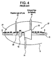
- the prior art as shown in Figure 4 may typically include a passive "leak-off" line 21 or extraction pipe placed to the immediate left of the skimmer. The purpose of the leak-off line 21 is to attempt to extract any high temperature steam that enters the HP stage, moves left towards the thrust piston and over the outer section of the thrust piston, and then moves past the skimmer so that it cannot continue to move left.
- This may be considered a "passive" system because the leak off line 21 flow cannot be actively controlled or adjusted because of the fixed source pressure, i.e., the structure is set at the time of the manufacture with virtually no control over excessive-wear induced issues as mentioned in the Background section above.
- a controllable first pressure tap 1 may be placed immediately to the left of the skimmer 20.
- a second controllable pressure tap 2 may be placed between the right-hand side of the skimmer 20 and to the left hand side of the thrust piston 15. These pressure taps (1,2) are connected to the secondary layer of active control pipes.
- the controller 23 may control the system to respond as follows.
- the second pressure tap 2 which may be a pressure/flow control valve will start controlling its valve openings to obtain the desired pressure on one side of the thrust bearing 15 to increase or decrease thrust.
- the first pressure tap 1 which may be a pressure control valve, will be adjusted along with the second tap 2, thereby maintaining a slightly higher (positive) pressure at the area connected to the second pressure tap 2.
- Both taps (1,2) may be controlled to match the lowest possible pressure needed to exactly match the amount of required thrust and sealing and cooling steam 6.
- first pressure tap 1 is connected to input control line 3 which is connected to the HP exhaust pipe 16 or "cold reheat.”
- Second pressure tap 2 is connected to output control line 4 which outputs to HP exhaust pipe 16.
- Pressure tap 1 is also connected to IP/LP control line 7 running between the high pressure casing 9 and the IP/LP casing 14.
- IP line 25 and P/F valve line 26 are included as shown in Figure 1.
- the P/F valve line 26 is connected to the LP/IP control line 7.
- a third valve, IP/LP pressure control valve 24 is also included in LP/IP control line 7 as shown in Figure 1.
- IP/LP pressure control valve 24 Three pressures P A , P B , and P C will be controlled as shown in Figure 1.
- the main role of the IP/LP pressure control valve 24 is to select upon direction from a controller 23 an appropriate intermediate or low pressure source P C to provide the control system enough of a pressure control margin to P B which is the pressure at the thrust control location relative to the thrust piston 15.
- P C source pressure
- P B valve opening via second pressure tap 2 for example
- P A pressure should be controlled simultaneously, and should be typically maintained slightly higher, for example about 5 psi higher than P B to minimize leak-off steam while controlling thrust. This forms the aforementioned positive pressure barrier around the skimmer 20 in Figure 1, and will prevent potentially dangerous hot leak-off steam from traveling to the left side of the thrust piston 15 at all times.
- Pressure sensors 22 may be located where appropriate. For example, sensors may typically be included near the first pressure tap 1 and second pressure tap 2, and near the thrust piston 15 as appropriate.
- a controller 23 reads the output from the pressure sensors 22 and provides active control of the first pressure tap 1 and second pressure tap 2.
- this active control system and method may create a +5 psi pressure barrier near the skimmer 20 wherein the cooling steam will flow from left to right over the skimmer 20 and into the output control line 4 piping connected to second pressure tap 2 which may be routed back to the boiler for reheating.
- an actively controllable pressure and thrust barrier is formed because first pressure tap 1 is controlled to be about 5 psi greater in pressure than second pressure tap 2.
- the controller 23 may control the system to respond as follows.
- the second pressure tap 2 which may be a pressure/flow control valve will start controlling its valve openings to obtain the desired pressure on one side of the thrust bearing 15 to increase or decrease thrust.
- the first pressure tap 1 which may be a pressure control valve, will be adjusted along with the second tap 2, thereby maintaining a slightly higher (positive) pressure at the area connected to the second pressure tap 2.
- Both taps (1,2) may be controlled to match the lowest possible pressure needed to exactly match the amount of required sealing and cooling steam 6.
- Table 1 the following control routine shown in Table 1 may be implemented depending upon the state of the turbine, start-up, steady-state, or additional thrust control needed.
- Table 1: VJ Vertical Joint (A location between IP and LP turbine) Mode Situation Bypass valve 24 (P C )open for Pressure/fl ow control valve 2 (P B )open for Pressure control valve 1 (P A ) Goals other than thrust control and positive P barrier/ remarks Controllabl e P at (P A ) Controllable P at (P B ) Design condition Steady State Full Load, no need for additional thrust LP VJ (or IP L-2 if it offers better sealing performa nce) Line 4 (Cold reheat P) as intended Fully open.
- the 5 psi (or appropriate) pressure difference can be achieved by selecting a precalculated location of the control-line (3,4) connections to the HP exhaust 16 which is a cold reheat line, i.e. x psi pressure difference can be naturally obtained initially without controlling the valves, but by using the natural pressure drop in the reheat line itself (61 in Figure 2).
- active control can be used for conditions where additional thrust is needed as indicated in
- P A , P B and P C pressures can be individually adjusted to a lower pressure than a source pressure by adjusting the amount of opening of the control valves. This enables a closer control of pressure at control locations than just shifting valve position simply from closed to fully open. By this feature, thrust force can be adjusted smoothly. This is still valid even when the upstream pressure (pressure on the right hand side of the thrust piston 15) varies.
- control pressure valve opening
- the control pressure can be optimized to best fit the operating condition, i.e. to minimize cooling steam needed in the system.
- the advantages of the present actively controlled protective pressure barrier and flexible thrust control include but are not limited to: enhancing turbine reliability by actively protecting bearings such as thrust bearings which may oil seals from failing or being damaged by high temperature steam in a steam turbine; maximizing machine efficiency by actively controlling the amount of cooling steam and the amount of steam dump for steam sealing in other locations in a steam turbine; and controlling thrust in the case of a design flaw, and thus providing an option for extra thrust as needed depending on operating conditions in a steam turbine.
- the present positive pressure-barrier and thrust control method may solve a number of additional problems.
- no safety device exists to protect a bearing, for example a thrust bearing, from high temperature steam in case of an N-packing failure in a steam turbine.
- the present positive pressure barrier method will prevent high temperature steam from the high-pressure casing of the steam turbine from reaching the bearing area regardless of a packing rub-off condition. This improves thrust bearing reliability by preventing potential thermal failure, and therefore improves machine reliability, life-span, and service intervals.
- Additional benefits in turbine design include the fact that the cooling flow is recirculated back to a cold reheat and reused in the reheater, therefore forming a closed flow loop instead of just forming a skimmed-off flow loop. This results in energy savings especially when there is massive rub-offs in N-packings.
- a mode of operation for the positive pressure barrier can be chosen out of multiple possible sets of valve settings.
- a pressure control valve combined with pressure/flow control valve a significant amount of cooling flow can be saved allowing only a minimum required steam flow in the packings to maintain a steam seal system. This is important because the amount of extracted cooling flow has non-negligible impact on turbine Heat Rate.
- the flexibility provided by being able to choose a different pressure source also eliminates problems associated with differential thermal expansion at an IP-HP vertical joint (VJ) during the startup.
- VJ IP-HP vertical joint
- the controller can choose to dump leak-off steam into the IP section 12 as needed until the turbine shell fully heats up.
Landscapes
- Engineering & Computer Science (AREA)
- Mechanical Engineering (AREA)
- General Engineering & Computer Science (AREA)
- Physics & Mathematics (AREA)
- Fluid Mechanics (AREA)
- Control Of Turbines (AREA)
- Turbine Rotor Nozzle Sealing (AREA)
Applications Claiming Priority (1)
| Application Number | Priority Date | Filing Date | Title |
|---|---|---|---|
| US10/905,307 US7195443B2 (en) | 2004-12-27 | 2004-12-27 | Variable pressure-controlled cooling scheme and thrust control arrangements for a steam turbine |
Publications (2)
| Publication Number | Publication Date |
|---|---|
| EP1701003A2 true EP1701003A2 (de) | 2006-09-13 |
| EP1701003A3 EP1701003A3 (de) | 2009-12-16 |
Family
ID=36611742
Family Applications (1)
| Application Number | Title | Priority Date | Filing Date |
|---|---|---|---|
| EP05257840A Withdrawn EP1701003A3 (de) | 2004-12-27 | 2005-12-20 | Methode zur aktiven Lagerdruckregelung in einer Dampfturbine |
Country Status (5)
| Country | Link |
|---|---|
| US (1) | US7195443B2 (de) |
| EP (1) | EP1701003A3 (de) |
| JP (1) | JP2006183666A (de) |
| CN (1) | CN100582440C (de) |
| RU (1) | RU2393357C2 (de) |
Families Citing this family (46)
| Publication number | Priority date | Publication date | Assignee | Title |
|---|---|---|---|---|
| DE102008022966B4 (de) * | 2008-05-09 | 2014-12-24 | Siemens Aktiengesellschaft | Rotationsmaschine |
| US8061970B2 (en) * | 2009-01-16 | 2011-11-22 | Dresser-Rand Company | Compact shaft support device for turbomachines |
| US8425180B2 (en) * | 2009-12-31 | 2013-04-23 | General Electric Company | Systems and apparatus relating to steam turbine operation |
| US8650878B2 (en) | 2010-03-02 | 2014-02-18 | General Electric Company | Turbine system including valve for leak off line for controlling seal steam flow |
| US8568084B2 (en) | 2010-06-23 | 2013-10-29 | General Electric Company | System for controlling thrust in steam turbine |
| US8480352B2 (en) * | 2010-06-23 | 2013-07-09 | General Electric Company | System for controlling thrust in steam turbine |
| JP5517785B2 (ja) * | 2010-06-30 | 2014-06-11 | 三菱重工業株式会社 | 蒸気タービンおよび蒸気タービンのスラスト調整方法 |
| US8864442B2 (en) | 2010-12-01 | 2014-10-21 | General Electric Company | Midspan packing pressure turbine diagnostic method |
| US20120148382A1 (en) * | 2010-12-09 | 2012-06-14 | Basf Se | Method and apparatus for the model-based monitoring of a turbomachine |
| US8994237B2 (en) | 2010-12-30 | 2015-03-31 | Dresser-Rand Company | Method for on-line detection of liquid and potential for the occurrence of resistance to ground faults in active magnetic bearing systems |
| EP2659277B8 (de) | 2010-12-30 | 2018-05-23 | Dresser-Rand Company | Verfahren zur online-erkennung von bodenwiderstandsfehlern in aktiven magnetlagersystemen |
| JP5818459B2 (ja) * | 2011-02-25 | 2015-11-18 | 三菱重工業株式会社 | 蒸気タービン駆動機、並びに、蒸気タービン駆動機を備えた船舶及びガス液化装置 |
| US9551349B2 (en) | 2011-04-08 | 2017-01-24 | Dresser-Rand Company | Circulating dielectric oil cooling system for canned bearings and canned electronics |
| EP2715167B1 (de) | 2011-05-27 | 2017-08-30 | Dresser-Rand Company | Segmentiertes auslauflager für magnetlagersysteme |
| US8851756B2 (en) | 2011-06-29 | 2014-10-07 | Dresser-Rand Company | Whirl inhibiting coast-down bearing for magnetic bearing systems |
| PL2599964T3 (pl) * | 2011-12-02 | 2016-10-31 | Układ turbiny parowej trójczłonowej turbiny parowej | |
| US9540942B2 (en) * | 2012-04-13 | 2017-01-10 | General Electric Company | Shaft sealing system for steam turbines |
| US9003799B2 (en) * | 2012-08-30 | 2015-04-14 | General Electric Company | Thermodynamic cycle optimization for a steam turbine cycle |
| EP3014086B1 (de) * | 2013-06-28 | 2021-06-16 | ExxonMobil Upstream Research Company | Systeme und verfahren zur verwendung von axialströmungsexpandern |
| WO2014208777A1 (en) | 2013-06-28 | 2014-12-31 | Mitsubishi Heavy Industries Compressor Corporation | Axial flow expander |
| US9341073B2 (en) | 2013-08-08 | 2016-05-17 | General Electric Company | Turbine thrust control system |
| US10247029B2 (en) * | 2016-02-04 | 2019-04-02 | United Technologies Corporation | Method for clearance control in a gas turbine engine |
| US11053847B2 (en) | 2016-12-28 | 2021-07-06 | Malta Inc. | Baffled thermoclines in thermodynamic cycle systems |
| US10458284B2 (en) | 2016-12-28 | 2019-10-29 | Malta Inc. | Variable pressure inventory control of closed cycle system with a high pressure tank and an intermediate pressure tank |
| US10233833B2 (en) | 2016-12-28 | 2019-03-19 | Malta Inc. | Pump control of closed cycle power generation system |
| US11574372B2 (en) | 2017-02-08 | 2023-02-07 | Upstream Data Inc. | Blockchain mine at oil or gas facility |
| US10871072B2 (en) | 2017-05-01 | 2020-12-22 | General Electric Company | Systems and methods for dynamic balancing of steam turbine rotor thrust |
| KR101986911B1 (ko) * | 2017-11-08 | 2019-06-07 | 두산중공업 주식회사 | 실링 압력 조절 시스템 및 이를 포함하는 증기터빈 |
| CN112106051A (zh) | 2018-01-11 | 2020-12-18 | 兰西姆有限责任公司 | 使用未利用的能量源对灵活数据中心进行动态电力输送的方法和系统 |
| US10982713B2 (en) | 2018-03-23 | 2021-04-20 | General Electric Company | Closed cycle heat engine |
| US10801549B2 (en) | 2018-05-31 | 2020-10-13 | General Electric Company | Axial load management system |
| CN114144743A (zh) | 2019-05-15 | 2022-03-04 | 上游数据公司 | 移动式区块链挖矿系统和使用方法 |
| US10618427B1 (en) | 2019-10-08 | 2020-04-14 | Lancium Llc | Behind-the-meter branch loads for electrical vehicle charging |
| CN116575994A (zh) | 2019-11-16 | 2023-08-11 | 马耳他股份有限公司 | 双动力系统泵送热电储存动力系统 |
| JP2021110289A (ja) * | 2020-01-10 | 2021-08-02 | 東芝エネルギーシステムズ株式会社 | タービンおよびスラスト力調整方法 |
| CA3076653A1 (en) | 2020-03-21 | 2021-09-21 | Upstream Data Inc. | Portable blockchain mining systems and methods of use |
| CA3188994A1 (en) | 2020-08-12 | 2022-02-17 | Benjamin R. Bollinger | Pumped heat energy storage system with district heating integration |
| US11396826B2 (en) | 2020-08-12 | 2022-07-26 | Malta Inc. | Pumped heat energy storage system with electric heating integration |
| US11486305B2 (en) | 2020-08-12 | 2022-11-01 | Malta Inc. | Pumped heat energy storage system with load following |
| US11286804B2 (en) | 2020-08-12 | 2022-03-29 | Malta Inc. | Pumped heat energy storage system with charge cycle thermal integration |
| BR112023002547A2 (pt) | 2020-08-12 | 2023-04-18 | Malta Inc | Sistema de armazenamento de energia térmica bombeada com turbomáquinas modulares |
| US11480067B2 (en) | 2020-08-12 | 2022-10-25 | Malta Inc. | Pumped heat energy storage system with generation cycle thermal integration |
| US11454167B1 (en) | 2020-08-12 | 2022-09-27 | Malta Inc. | Pumped heat energy storage system with hot-side thermal integration |
| CN112903168B (zh) * | 2021-01-25 | 2022-07-22 | 杭州汽轮机股份有限公司 | 一种汽轮机轴向推力快速监测方法 |
| AU2022413246A1 (en) | 2021-12-14 | 2024-07-04 | Malta Inc. | Pumped heat energy storage system integrated with coal-fired energy generation unit |
| IT202200013819A1 (it) * | 2022-06-30 | 2023-12-30 | Nuovo Pignone Tecnologie Srl | OnLine Rotor Thrust Adjustment System |
Citations (5)
| Publication number | Priority date | Publication date | Assignee | Title |
|---|---|---|---|---|
| EP1033475A1 (de) | 1999-03-02 | 2000-09-06 | Asea Brown Boveri AG | Regelung des axialen Schubausgleichs bei Wellen von Turbomaschinen |
| EP1281836A2 (de) | 2001-08-03 | 2003-02-05 | Atlas Copco Energas Gmbh | Turbomaschine |
| US6705086B1 (en) | 2002-12-06 | 2004-03-16 | General Electric Company | Active thrust control system for combined cycle steam turbines with large steam extraction |
| US6892540B1 (en) | 2004-05-27 | 2005-05-17 | General Electric Company | System and method for controlling a steam turbine |
| US6957945B2 (en) | 2002-11-27 | 2005-10-25 | General Electric Company | System to control axial thrust loads for steam turbines |
Family Cites Families (9)
| Publication number | Priority date | Publication date | Assignee | Title |
|---|---|---|---|---|
| SU42096A1 (ru) * | 1934-03-14 | 1935-03-31 | В.В. Швецов | Гидравлический упорный подшипник |
| US4557664A (en) * | 1983-04-13 | 1985-12-10 | Dresser Industries, Inc. | Control of steam turbine shaft thrust loads |
| SU1460450A1 (ru) * | 1986-10-21 | 1989-02-23 | Производственно-техническое предприятие "Уралэнергочермет" | Упорный подшипник |
| US4961310A (en) * | 1989-07-03 | 1990-10-09 | General Electric Company | Single shaft combined cycle turbine |
| JP3021779B2 (ja) * | 1991-06-12 | 2000-03-15 | 富士電機株式会社 | 蒸気タービン |
| JPH0559901A (ja) * | 1991-08-30 | 1993-03-09 | Mitsubishi Heavy Ind Ltd | タービンのバランスピストン |
| JPH08189302A (ja) * | 1995-01-06 | 1996-07-23 | Mitsubishi Heavy Ind Ltd | スラスト自動調整装置 |
| PL183594B1 (pl) * | 1996-04-11 | 2002-06-28 | Siemens Ag | Sposób kompensowania sił poosiowych w maszynie wirnikowej i maszyna wirnikowa |
| DE19951570A1 (de) * | 1999-10-27 | 2001-05-03 | Abb Patent Gmbh | Einrichtung zur Kompensierung des Axialschubs bei Turbomaschinen |
-
2004
- 2004-12-27 US US10/905,307 patent/US7195443B2/en not_active Expired - Fee Related
-
2005
- 2005-12-20 EP EP05257840A patent/EP1701003A3/de not_active Withdrawn
- 2005-12-20 JP JP2005365812A patent/JP2006183666A/ja active Pending
- 2005-12-26 RU RU2005140668/06A patent/RU2393357C2/ru not_active IP Right Cessation
- 2005-12-27 CN CN200510121670.XA patent/CN100582440C/zh not_active Expired - Fee Related
Patent Citations (5)
| Publication number | Priority date | Publication date | Assignee | Title |
|---|---|---|---|---|
| EP1033475A1 (de) | 1999-03-02 | 2000-09-06 | Asea Brown Boveri AG | Regelung des axialen Schubausgleichs bei Wellen von Turbomaschinen |
| EP1281836A2 (de) | 2001-08-03 | 2003-02-05 | Atlas Copco Energas Gmbh | Turbomaschine |
| US6957945B2 (en) | 2002-11-27 | 2005-10-25 | General Electric Company | System to control axial thrust loads for steam turbines |
| US6705086B1 (en) | 2002-12-06 | 2004-03-16 | General Electric Company | Active thrust control system for combined cycle steam turbines with large steam extraction |
| US6892540B1 (en) | 2004-05-27 | 2005-05-17 | General Electric Company | System and method for controlling a steam turbine |
Also Published As
| Publication number | Publication date |
|---|---|
| JP2006183666A (ja) | 2006-07-13 |
| US7195443B2 (en) | 2007-03-27 |
| EP1701003A3 (de) | 2009-12-16 |
| RU2005140668A (ru) | 2007-07-10 |
| CN100582440C (zh) | 2010-01-20 |
| RU2393357C2 (ru) | 2010-06-27 |
| CN1847626A (zh) | 2006-10-18 |
| US20060140747A1 (en) | 2006-06-29 |
Similar Documents
| Publication | Publication Date | Title |
|---|---|---|
| US7195443B2 (en) | Variable pressure-controlled cooling scheme and thrust control arrangements for a steam turbine | |
| US5660037A (en) | Method for conversion of a reheat steam turbine power plant to a non-reheat combined cycle power plant | |
| US6339926B1 (en) | Steam-cooled gas turbine combined power plant | |
| US7101144B2 (en) | Steam turbine rotor, steam turbine and method for actively cooling a steam turbine rotor and use of active cooling | |
| JP5860597B2 (ja) | 排熱回収ボイラ配管を予熱するシステム及び方法 | |
| CN203809061U (zh) | 蒸汽涡轮 | |
| JP2010216477A (ja) | 熱回収蒸気発生器及び関連する蒸気ラインを予め加温するためのシステム及び方法 | |
| KR102719198B1 (ko) | 연소 터빈 엔진을 위한 연료 예열 시스템 | |
| JPS61237802A (ja) | 蒸気タ−ビンの暖機方法 | |
| JP2010014114A (ja) | 蒸気タービン過負荷バルブ及びそれに関連する方法 | |
| JP5517785B2 (ja) | 蒸気タービンおよび蒸気タービンのスラスト調整方法 | |
| US20200131990A1 (en) | Inlet air heating systems for combined cycle power plants | |
| JP5762222B2 (ja) | 蒸気タービン設備 | |
| CA2828449A1 (en) | Combined cycle power plant | |
| JP5047096B2 (ja) | 蒸気弁装置 | |
| JPH02230905A (ja) | ガスタービン・蒸気タービン組合せサイクルの超過速度防護装置 | |
| JP2005315122A (ja) | 蒸気タービン | |
| EP2650485B1 (de) | Wellendichtungssystem für Dampfturbinen | |
| CN102770625B (zh) | 火力发电站和用于运行其中的调整式涡轮机的方法 | |
| US7086828B2 (en) | Steam turbine and method for operating a steam turbine | |
| US20180135467A1 (en) | Cooling of gas turbine at varying loads | |
| JP5072767B2 (ja) | 蒸気タービン用蒸気弁 | |
| JP4413732B2 (ja) | 蒸気タービンプラント | |
| KR102133491B1 (ko) | 터빈을 이용한 발전장치 및 모터를 이용한 압축장치 | |
| CN107795340B (zh) | 涡轮机温度控制系统 |
Legal Events
| Date | Code | Title | Description |
|---|---|---|---|
| PUAI | Public reference made under article 153(3) epc to a published international application that has entered the european phase |
Free format text: ORIGINAL CODE: 0009012 |
|
| AK | Designated contracting states |
Kind code of ref document: A2 Designated state(s): AT BE BG CH CY CZ DE DK EE ES FI FR GB GR HU IE IS IT LI LT LU LV MC NL PL PT RO SE SI SK TR |
|
| AX | Request for extension of the european patent |
Extension state: AL BA HR MK YU |
|
| PUAL | Search report despatched |
Free format text: ORIGINAL CODE: 0009013 |
|
| AK | Designated contracting states |
Kind code of ref document: A3 Designated state(s): AT BE BG CH CY CZ DE DK EE ES FI FR GB GR HU IE IS IT LI LT LU LV MC NL PL PT RO SE SI SK TR |
|
| AX | Request for extension of the european patent |
Extension state: AL BA HR MK YU |
|
| 17P | Request for examination filed |
Effective date: 20100616 |
|
| AKX | Designation fees paid |
Designated state(s): DE FR GB |
|
| 17Q | First examination report despatched |
Effective date: 20100730 |
|
| STAA | Information on the status of an ep patent application or granted ep patent |
Free format text: STATUS: THE APPLICATION IS DEEMED TO BE WITHDRAWN |
|
| 18D | Application deemed to be withdrawn |
Effective date: 20120703 |