EP1701088B1 - Fern- und Abblendlichtschaltvorrichtung - Google Patents
Fern- und Abblendlichtschaltvorrichtung Download PDFInfo
- Publication number
- EP1701088B1 EP1701088B1 EP06101134A EP06101134A EP1701088B1 EP 1701088 B1 EP1701088 B1 EP 1701088B1 EP 06101134 A EP06101134 A EP 06101134A EP 06101134 A EP06101134 A EP 06101134A EP 1701088 B1 EP1701088 B1 EP 1701088B1
- Authority
- EP
- European Patent Office
- Prior art keywords
- plate
- solenoid valve
- switching apparatus
- notch
- anchor plate
- Prior art date
- Legal status (The legal status is an assumption and is not a legal conclusion. Google has not performed a legal analysis and makes no representation as to the accuracy of the status listed.)
- Expired - Lifetime
Links
Images



Classifications
-
- F—MECHANICAL ENGINEERING; LIGHTING; HEATING; WEAPONS; BLASTING
- F21—LIGHTING
- F21S—NON-PORTABLE LIGHTING DEVICES; SYSTEMS THEREOF; VEHICLE LIGHTING DEVICES SPECIALLY ADAPTED FOR VEHICLE EXTERIORS
- F21S41/00—Illuminating devices specially adapted for vehicle exteriors, e.g. headlamps
- F21S41/60—Illuminating devices specially adapted for vehicle exteriors, e.g. headlamps characterised by a variable light distribution
- F21S41/68—Illuminating devices specially adapted for vehicle exteriors, e.g. headlamps characterised by a variable light distribution by acting on screens
- F21S41/683—Illuminating devices specially adapted for vehicle exteriors, e.g. headlamps characterised by a variable light distribution by acting on screens by moving screens
- F21S41/686—Blades, i.e. screens moving in a vertical plane
Definitions
- the invention relates to a light beam and low beam switching apparatus.
- German patent No. DE 202004020183.6 discloses "An improved High beam and low beam switching apparatus" which includes (referring to its Claim 1) an anchor plate and a mask interposed between a lamp socket of a lighting element and a light penetrating cover; the anchor plate is positioned transversely and has a notch on a upper end corresponding to the lighting element and a lower end fastened to a solenoid valve; the mask plate is driven by the solenoid valve.
- the mask having a lower end hinged on one side of the notch of the anchor plate and a push plate extended and bent from the lower end towards the light source that has a driving hole to be coupled with a stem of the solenoid valve; the stem being extendable to sway the mask thereby to change light projecting area to switch the high beam and low beam.
- the push plate of the mask with the elongated driving hole set forth above has to be bent to mate the stem (referring to its Claim 3), and the distal end has be formed two annular grooves by fabrication to be wedged by C-shaped clips. Fabrication process is complex. This is the first disadvantage.
- the stem runs through the longitudinal and elongated driving hole and is confined by two C-shaped clips.
- a return spring is added to aid pulling (referring to its Claim 4).
- the structure is complicated. Fabrication and assembly are more difficult, and production time is longer. This is the second disadvantage.
- the stem runs through the longitudinal and elongated driving hole and is confined by two C-shaped clips on the front and read distal ends. While the mask is driven and swayed, the two C-shaped clips slide on two sides of the elongated driving hole and generate friction. This affects operation smoothness and steadiness. This is the third disadvantage.
- the stem has a bent section to generate friction with the elongated driving hole during operation. As a result, loading and wearing occur to the related elements, and service life is shortened. This is the fourth disadvantage.
- the present invention aims to provide improvements to overcome those problems.
- the primary object of the invention is to provide a high beam and low beam switching apparatus that has a lower moving friction force to make swaying smoother and steadier during switching operation.
- Another object of the invention to provide a high beam and low beam switching apparatus that can reduce loading of the solenoid valve so that operation load is lower and durability increases.
- the life span of the solenoid valve also is longer.
- Yet another object of the invention is to provide a high beam and low beam switching apparatus that has simplified elements, thus is easier to fabricate and assemble, and can reduce production cost and improve economic effectiveness.
- the invention includes a transverse anchor plate located between a lamp socket of a lighting element and a light penetrating cover.
- the anchor plate has a notch on a upper end corresponding to the lighting element and a lower end coupling with a solenoid valve which drives a mask plate.
- the anchor plate has two jutting hinge docks on two sides below the notch on one side facing the solenoid valve;
- the mask plate has two pivotal plates extended from a lower end each has two pivotal holes formed thereon in a spaced manner;
- the mask plate and the anchor plate are pivotally coupled through two ends of an elastic latch member which is engaged with the solenoid valve;
- a drawing plate is provided which has two ends running through the pivotal holes of the pivotal plates of the mask plate and a coupling slot in the middle to latch on a upper portion of a stem of the solenoid valve to compress a upper end of a returning element.
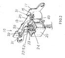
- the switching apparatus 10 includes a semi-circular anchor plate 11, a solenoid valve 20, a mask plate 30, a drawing plate 50 and a T-shaped padding blade 60.
- the anchor plate 11 is substantially directing downwards and has two anchor arms 12 extended outwards from two sides to be fastened to a lamp socket, a notch 13 on a upper end, and spaced fastening holes 14 in the middle portion and two hinge docks 15 on two sides of the notch 13.
- the solenoid valve 20 is fastened to the anchor plate 11 by coupling screws 21 with the fastening holes 14 and includes a stem 24 which has a neck 22 on a distal end with an annular groove formed thereon and is coupled with a returning element 23.
- the mask plate 30 has two pivotal plates 32 on two ends directing upwards in an inclined manner each has a upper pivot hole 31 and a lower pivot hole 31' that is coupled with two ends of an elastic latch member 40 of the solenoid valve 20 to be hinged on the hinge docks 15 of the anchor plate 11.
- the drawing plate 50 has two ends running through the upper pivot hole 31 of the mask plate 30 for anchoring and an extension plate 51 in the middle portion with a coupling slot 52 formed thereon.
- the coupling slot 52 is wedged in the neck 22 of the stem 24 of the solenoid valve 20 to confine the returning element 23.
- the hinge docks 15 can be directly formed from the anchor plate 11 by stamping.
- the T-shaped padding blade 60 is fastened to the solenoid valve 20 by screwing through the anchor plate 11 to cover the opening adjacent to the hinge docks 15 that are formed while the hinge docks 15 are bent.
- the stem 24 of the solenoid valve 20 can move the drawing plate 50 up and down linearly to sway the mask plate 30.
- Friction resistance among the elements can be reduced and the loading on the solenoid valve 20 decreases.
- the durability of the solenoid valve 20 increases and the life span is longer.
- the switching apparatus 10 is installed on a lamp socket 70 which has a refraction reflective trough 71.
- the refraction reflective trough 71 holds a lighting element 72 in the middle.
- the lamp socket 70 and a light penetrating cover 80 of a convex lens 81 at the front end are interposed by a coupling frame 90 to fasten the anchor plate 11 in a transverse manner.
- the solenoid valve 20 can be held securely to drive the mask plate 30.
- the anchor plate 11 is fastened to one end of the refraction reflective trough 71 of the lamp socket 70.
- the notch 13 on the upper side of the anchor plate 11 is aligned with a refractive high beam light source on the lower side of the lighting element 72 in the lamp socket 70.
- the solenoid valve 20 can move the mask plate 30 synchronously to sway a desired angle in the notch 13 on the upper side of the anchor plate 11.
- the stem 24 moves the drawing plate 50 downwards to sway the mask plate 30 outwards, and the notch 13 on the upper side of the anchor plate 11 is opened; the high beam projected and refracted from the lighting element 72 is not blocked, thus can project outwards through the notch 13 to form a high beam.
- FIG. 5 for an embodiment of the invention in use for a low beam condition.
- the stem 24 is pushed by the returning element 23 to its original position.
- the drawing plate 50 is moved upwards to sway the mask plate 30 upwards in contact with the anchor plate 11 and block the notch 13.
- the high beam refracted from the lighting element 72 is blocked without projecting outwards, and only the low beam is projected.
- the high beam and low beam switching apparatus of the invention set forth above has a simple structure and can be fabricated and assembled easily. It has a lower friction among the moving elements, thus can operate smoother and steadier. The loading and wearing of the elements are reduced, and durability is enhanced.
Landscapes
- Engineering & Computer Science (AREA)
- General Engineering & Computer Science (AREA)
- Non-Portable Lighting Devices Or Systems Thereof (AREA)
- Variable-Direction Aerials And Aerial Arrays (AREA)
- Vehicle Cleaning, Maintenance, Repair, Refitting, And Outriggers (AREA)
- Fastening Of Light Sources Or Lamp Holders (AREA)
- Diaphragms For Cameras (AREA)
- Illuminated Signs And Luminous Advertising (AREA)
- Lighting Device Outwards From Vehicle And Optical Signal (AREA)
- Lasers (AREA)
- Superconductors And Manufacturing Methods Therefor (AREA)
Claims (4)
- Fern- und Abblendlicht-Schaltvorrichtung (10) aufweisend eine Ankerplatte (11), die transversal an einem Lampensockel (70) befestigt ist und an einem oberen Ende entsprechend einem Beleuchtungselement (72) eine Kerbe (13) aufweist, eine schwenkbar mit der Ankerplatte (11) gekoppelte Maskenplatte (30) unter der Kerbe (13) und ein zum Variieren der Maskenplatte (30) an einem unteren Ende der Ankerplatte (11) mittels Schrauben (21) befestigtes Magnetventil (20), dadurch gekennzeichnet, dass:die Ankerplatte (11) zwei herausstehende Drehkopplungen (15) an zwei Seiten der Kerbe (13) aufweist;das Magnetventil (20) einen sich in Richtung Kerbe (13) erstreckenden Stutzen (24) aufweist und mit einem Rückkehrelement (23) gekoppelt ist;die Maskenplatte (30) zwei als Drehpunkt dienende Platten (32) aufweist, die sich in einer geneigten Weise von zwei Seiten eines unteren Endes der Maskenplatte (30) nach oben erstrecken und die jeweils ein oberes Drehloch (31) und ein unteres Drehloch (31') aufweisen, wobei das untere Drehloch (31') mit der Drehkopplung (15) durch zwei Enden eines elastischen Schnappelements (40) hindurch drehbar gekoppelt ist, so dass sich die Maskenplatte (30) nahe der Kerbe (13) befindet;eine Ziehplatte (50) bereitgestellt ist, die einen mit dem Stutzen (24) im Eingriff stehenden Mittelabschnitt aufweist, um ein oberes Ende des Rückkehrelements (23) und zwei in das obere Drehloch (31) einführende Enden zusammenzudrücken, wodurch der Stutzen (24) des Magnetventils (20) dehnbar ist, um die Ziehplatte (50) zum Variieren der Maskenplatte (30) zu ziehen, so dass Widerstandsreibung auf Grund Bewegung reduziert ist, um gleichmäßigen und ruckfreien Betrieb der Fern- und Abblendlicht-Schaltvorrichtung möglich zu machen.
- Fern- und Abblendlicht-Schaltvorrichtung gemäß Anspruch 1, wobei das elastische Schnappelement (40) einen in einer U-Form ausgebildeten Mittelabschnitt zum Koppeln mit dem Magnetventil (20) aufweist.
- Fern- und Abblendlicht-Schaltvorrichtung gemäß Anspruch 1, wobei der Stutzen (24) des Magnetventils (20) an einem distalen Ende einen eingekerbten Kragen (22) aufweist, wobei die Ziehplatte (50) in einem Mittelabschnitt eine Ausdehnungsplatte (51) aufweist, die einen Schlitz (52) zum Einklemmen des Kragens (22) aufweist.
- Fern- und Abblendlicht-Schaltvorrichtung gemäß Anspruch 1, wobei die Drehkopplungen (15) mittels Stanzens der Ankerplatte (11) hergestellt sind, wobei die Ankerplatte (11) durch ein abfederndes Blatt (60) hindurch, das während Biegens der Drehkopplungen (15) gebildete Öffnungen abdeckt, an das Magnetventil (20) angeschraubt ist.
Priority Applications (3)
| Application Number | Priority Date | Filing Date | Title |
|---|---|---|---|
| DE602006000918T DE602006000918T2 (de) | 2006-02-01 | 2006-02-01 | Fern- und Abblendlichtschaltvorrichtung |
| EP06101134A EP1701088B8 (de) | 2006-02-01 | 2006-02-01 | Fern- und Abblendlichtschaltvorrichtung |
| AT06101134T ATE392585T1 (de) | 2006-02-01 | 2006-02-01 | Fern- und abblendlichtschaltvorrichtung |
Applications Claiming Priority (1)
| Application Number | Priority Date | Filing Date | Title |
|---|---|---|---|
| EP06101134A EP1701088B8 (de) | 2006-02-01 | 2006-02-01 | Fern- und Abblendlichtschaltvorrichtung |
Publications (3)
| Publication Number | Publication Date |
|---|---|
| EP1701088A1 EP1701088A1 (de) | 2006-09-13 |
| EP1701088B1 true EP1701088B1 (de) | 2008-04-16 |
| EP1701088B8 EP1701088B8 (de) | 2008-06-25 |
Family
ID=36146954
Family Applications (1)
| Application Number | Title | Priority Date | Filing Date |
|---|---|---|---|
| EP06101134A Expired - Lifetime EP1701088B8 (de) | 2006-02-01 | 2006-02-01 | Fern- und Abblendlichtschaltvorrichtung |
Country Status (3)
| Country | Link |
|---|---|
| EP (1) | EP1701088B8 (de) |
| AT (1) | ATE392585T1 (de) |
| DE (1) | DE602006000918T2 (de) |
Cited By (1)
| Publication number | Priority date | Publication date | Assignee | Title |
|---|---|---|---|---|
| DE102009041265A1 (de) * | 2009-09-11 | 2011-03-24 | Huang, Hsian-Yi | Steuervorrichtung für Fern- und Abblendlicht eines Scheinwerfers |
Families Citing this family (2)
| Publication number | Priority date | Publication date | Assignee | Title |
|---|---|---|---|---|
| DE102011016112B4 (de) * | 2011-04-05 | 2013-02-28 | Yah Ter Enterprise Co., Ltd. | Vorrichtung zur Steuerung des Fern- und Abblendlichts eines Fahrzeugscheinwerfers |
| DE102017011105B4 (de) * | 2017-11-30 | 2019-08-01 | Hsiang-Yi Huang | Abblendlicht-Fernlicht-Umschaltvorrichtung für Fahrzeugscheinwerferlampen |
Family Cites Families (3)
| Publication number | Priority date | Publication date | Assignee | Title |
|---|---|---|---|---|
| FR2769071B1 (fr) * | 1997-09-26 | 1999-12-03 | Valeo Vision | Projecteur de type elliptique a faisceau variable, notamment pour vehicule automobile |
| JP4193713B2 (ja) * | 2004-02-02 | 2008-12-10 | 市光工業株式会社 | ヘッドランプ |
| DE202004020183U1 (de) * | 2004-12-30 | 2005-03-24 | Wang Jen Mao | Umschaltevorrichtung für Fern- und Nahlicht |
-
2006
- 2006-02-01 AT AT06101134T patent/ATE392585T1/de not_active IP Right Cessation
- 2006-02-01 EP EP06101134A patent/EP1701088B8/de not_active Expired - Lifetime
- 2006-02-01 DE DE602006000918T patent/DE602006000918T2/de not_active Expired - Lifetime
Cited By (1)
| Publication number | Priority date | Publication date | Assignee | Title |
|---|---|---|---|---|
| DE102009041265A1 (de) * | 2009-09-11 | 2011-03-24 | Huang, Hsian-Yi | Steuervorrichtung für Fern- und Abblendlicht eines Scheinwerfers |
Also Published As
| Publication number | Publication date |
|---|---|
| ATE392585T1 (de) | 2008-05-15 |
| DE602006000918T2 (de) | 2009-06-10 |
| EP1701088A1 (de) | 2006-09-13 |
| EP1701088B8 (de) | 2008-06-25 |
| DE602006000918D1 (de) | 2008-05-29 |
Similar Documents
| Publication | Publication Date | Title |
|---|---|---|
| US7230199B2 (en) | Multi-stage button switch | |
| US7896568B2 (en) | Articulite | |
| US5860189A (en) | Door wheel | |
| US20020045503A1 (en) | Blade-type mechanical chain tensioner with external strengthening rib | |
| EP3835651B1 (de) | Reflektorlampe mit push-push-verstellanordnung zur veränderung eines lichtstrahlwinkels davon | |
| EP2230370B1 (de) | Scharnieranordnung mit mittlerem Element, Fenster mit der Scharnieranordnung und Verwendung der Scharnieranordnung | |
| KR930006283A (ko) | 래칫형 래치장치 | |
| CA2346623A1 (en) | Plug door drive system | |
| US7335211B2 (en) | Transmission system of eyebrow-beautifying device | |
| GB2047309A (en) | Improvements in friction supporting stays for windows | |
| US7520649B2 (en) | Switching device for switching between low beam mode and high beam mode of a xenon headlight | |
| EP1701088A1 (de) | Fern- und Abblendlichtschaltvorrichtung | |
| CN112360283A (zh) | 调节组件、传送机构及平趟门 | |
| KR20030028493A (ko) | 라인 안내 장치 | |
| US20200124253A1 (en) | Reflector Lamp With Push-Push Adjustment Assembly For Varying A light Beam Angle Thereof | |
| KR200300419Y1 (ko) | 도어용 안전장치 | |
| CN108061176B (zh) | 多通道切换阀 | |
| KR19990017571U (ko) | 가로등의반사판조절장치 | |
| CN223319384U (zh) | 驱动组件、搁物架及冰箱 | |
| KR20230112878A (ko) | Led천정등용 고정로커 및 이를 구비한 고정장치 | |
| CN221780624U (zh) | 灯杆和灯具 | |
| KR20220169136A (ko) | 방화도어 개방유지장치 | |
| JP2019029156A (ja) | 照明器具 | |
| KR100378873B1 (ko) | 충격 흡수용 차선유도 표시기 | |
| CN223319383U (zh) | 驱动组件、搁物架及冰箱 |
Legal Events
| Date | Code | Title | Description |
|---|---|---|---|
| PUAI | Public reference made under article 153(3) epc to a published international application that has entered the european phase |
Free format text: ORIGINAL CODE: 0009012 |
|
| 17P | Request for examination filed |
Effective date: 20060720 |
|
| AK | Designated contracting states |
Kind code of ref document: A1 Designated state(s): AT BE BG CH CY CZ DE DK EE ES FI FR GB GR HU IE IS IT LI LT LU LV MC NL PL PT RO SE SI SK TR |
|
| AX | Request for extension of the european patent |
Extension state: AL BA HR MK YU |
|
| AKX | Designation fees paid |
Designated state(s): AT BE BG CH CY CZ DE DK EE ES FI FR GB GR HU IE IS IT LI LT LU LV MC NL PL PT RO SE SI SK TR |
|
| GRAP | Despatch of communication of intention to grant a patent |
Free format text: ORIGINAL CODE: EPIDOSNIGR1 |
|
| RIN1 | Information on inventor provided before grant (corrected) |
Inventor name: TSAI, CHIH MING Inventor name: LEE, JIHN-SHIUN Inventor name: WANG, JEN-MAO |
|
| GRAS | Grant fee paid |
Free format text: ORIGINAL CODE: EPIDOSNIGR3 |
|
| GRAA | (expected) grant |
Free format text: ORIGINAL CODE: 0009210 |
|
| AK | Designated contracting states |
Kind code of ref document: B1 Designated state(s): AT BE BG CH CY CZ DE DK EE ES FI FR GB GR HU IE IS IT LI LT LU LV MC NL PL PT RO SE SI SK TR |
|
| REG | Reference to a national code |
Ref country code: CH Ref legal event code: EP |
|
| RAP2 | Party data changed (patent owner data changed or rights of a patent transferred) |
Owner name: GET TAI AUTO ACCESSORIES CO., LTD. Owner name: FU AN INDUSTRIAL CO., LTD. |
|
| REG | Reference to a national code |
Ref country code: IE Ref legal event code: FG4D |
|
| REF | Corresponds to: |
Ref document number: 602006000918 Country of ref document: DE Date of ref document: 20080529 Kind code of ref document: P |
|
| NLT2 | Nl: modifications (of names), taken from the european patent patent bulletin |
Owner name: GET TAI AUTO ACCESSORIES CO., LTD. EN FU AN INDUST Effective date: 20080521 |
|
| PG25 | Lapsed in a contracting state [announced via postgrant information from national office to epo] |
Ref country code: SI Free format text: LAPSE BECAUSE OF FAILURE TO SUBMIT A TRANSLATION OF THE DESCRIPTION OR TO PAY THE FEE WITHIN THE PRESCRIBED TIME-LIMIT Effective date: 20080416 |
|
| NLV1 | Nl: lapsed or annulled due to failure to fulfill the requirements of art. 29p and 29m of the patents act | ||
| PG25 | Lapsed in a contracting state [announced via postgrant information from national office to epo] |
Ref country code: BG Free format text: LAPSE BECAUSE OF FAILURE TO SUBMIT A TRANSLATION OF THE DESCRIPTION OR TO PAY THE FEE WITHIN THE PRESCRIBED TIME-LIMIT Effective date: 20080716 Ref country code: ES Free format text: LAPSE BECAUSE OF FAILURE TO SUBMIT A TRANSLATION OF THE DESCRIPTION OR TO PAY THE FEE WITHIN THE PRESCRIBED TIME-LIMIT Effective date: 20080727 Ref country code: PT Free format text: LAPSE BECAUSE OF FAILURE TO SUBMIT A TRANSLATION OF THE DESCRIPTION OR TO PAY THE FEE WITHIN THE PRESCRIBED TIME-LIMIT Effective date: 20080916 Ref country code: NL Free format text: LAPSE BECAUSE OF FAILURE TO SUBMIT A TRANSLATION OF THE DESCRIPTION OR TO PAY THE FEE WITHIN THE PRESCRIBED TIME-LIMIT Effective date: 20080416 Ref country code: FI Free format text: LAPSE BECAUSE OF FAILURE TO SUBMIT A TRANSLATION OF THE DESCRIPTION OR TO PAY THE FEE WITHIN THE PRESCRIBED TIME-LIMIT Effective date: 20080416 |
|
| PG25 | Lapsed in a contracting state [announced via postgrant information from national office to epo] |
Ref country code: LV Free format text: LAPSE BECAUSE OF FAILURE TO SUBMIT A TRANSLATION OF THE DESCRIPTION OR TO PAY THE FEE WITHIN THE PRESCRIBED TIME-LIMIT Effective date: 20080416 Ref country code: AT Free format text: LAPSE BECAUSE OF FAILURE TO SUBMIT A TRANSLATION OF THE DESCRIPTION OR TO PAY THE FEE WITHIN THE PRESCRIBED TIME-LIMIT Effective date: 20080416 Ref country code: PL Free format text: LAPSE BECAUSE OF FAILURE TO SUBMIT A TRANSLATION OF THE DESCRIPTION OR TO PAY THE FEE WITHIN THE PRESCRIBED TIME-LIMIT Effective date: 20080416 |
|
| PG25 | Lapsed in a contracting state [announced via postgrant information from national office to epo] |
Ref country code: IS Free format text: LAPSE BECAUSE OF FAILURE TO SUBMIT A TRANSLATION OF THE DESCRIPTION OR TO PAY THE FEE WITHIN THE PRESCRIBED TIME-LIMIT Effective date: 20080816 |
|
| PG25 | Lapsed in a contracting state [announced via postgrant information from national office to epo] |
Ref country code: LT Free format text: LAPSE BECAUSE OF FAILURE TO SUBMIT A TRANSLATION OF THE DESCRIPTION OR TO PAY THE FEE WITHIN THE PRESCRIBED TIME-LIMIT Effective date: 20080416 Ref country code: SE Free format text: LAPSE BECAUSE OF FAILURE TO SUBMIT A TRANSLATION OF THE DESCRIPTION OR TO PAY THE FEE WITHIN THE PRESCRIBED TIME-LIMIT Effective date: 20080716 Ref country code: CZ Free format text: LAPSE BECAUSE OF FAILURE TO SUBMIT A TRANSLATION OF THE DESCRIPTION OR TO PAY THE FEE WITHIN THE PRESCRIBED TIME-LIMIT Effective date: 20080416 Ref country code: DK Free format text: LAPSE BECAUSE OF FAILURE TO SUBMIT A TRANSLATION OF THE DESCRIPTION OR TO PAY THE FEE WITHIN THE PRESCRIBED TIME-LIMIT Effective date: 20080416 |
|
| ET | Fr: translation filed | ||
| PLBE | No opposition filed within time limit |
Free format text: ORIGINAL CODE: 0009261 |
|
| STAA | Information on the status of an ep patent application or granted ep patent |
Free format text: STATUS: NO OPPOSITION FILED WITHIN TIME LIMIT |
|
| PG25 | Lapsed in a contracting state [announced via postgrant information from national office to epo] |
Ref country code: RO Free format text: LAPSE BECAUSE OF FAILURE TO SUBMIT A TRANSLATION OF THE DESCRIPTION OR TO PAY THE FEE WITHIN THE PRESCRIBED TIME-LIMIT Effective date: 20080416 Ref country code: BE Free format text: LAPSE BECAUSE OF FAILURE TO SUBMIT A TRANSLATION OF THE DESCRIPTION OR TO PAY THE FEE WITHIN THE PRESCRIBED TIME-LIMIT Effective date: 20080416 Ref country code: SK Free format text: LAPSE BECAUSE OF FAILURE TO SUBMIT A TRANSLATION OF THE DESCRIPTION OR TO PAY THE FEE WITHIN THE PRESCRIBED TIME-LIMIT Effective date: 20080416 |
|
| 26N | No opposition filed |
Effective date: 20090119 |
|
| PG25 | Lapsed in a contracting state [announced via postgrant information from national office to epo] |
Ref country code: EE Free format text: LAPSE BECAUSE OF FAILURE TO SUBMIT A TRANSLATION OF THE DESCRIPTION OR TO PAY THE FEE WITHIN THE PRESCRIBED TIME-LIMIT Effective date: 20080416 |
|
| PG25 | Lapsed in a contracting state [announced via postgrant information from national office to epo] |
Ref country code: MC Free format text: LAPSE BECAUSE OF NON-PAYMENT OF DUE FEES Effective date: 20090228 Ref country code: CY Free format text: LAPSE BECAUSE OF FAILURE TO SUBMIT A TRANSLATION OF THE DESCRIPTION OR TO PAY THE FEE WITHIN THE PRESCRIBED TIME-LIMIT Effective date: 20080416 |
|
| REG | Reference to a national code |
Ref country code: IE Ref legal event code: MM4A |
|
| PG25 | Lapsed in a contracting state [announced via postgrant information from national office to epo] |
Ref country code: IE Free format text: LAPSE BECAUSE OF NON-PAYMENT OF DUE FEES Effective date: 20090202 |
|
| REG | Reference to a national code |
Ref country code: CH Ref legal event code: PL |
|
| PG25 | Lapsed in a contracting state [announced via postgrant information from national office to epo] |
Ref country code: GR Free format text: LAPSE BECAUSE OF FAILURE TO SUBMIT A TRANSLATION OF THE DESCRIPTION OR TO PAY THE FEE WITHIN THE PRESCRIBED TIME-LIMIT Effective date: 20080717 Ref country code: LI Free format text: LAPSE BECAUSE OF NON-PAYMENT OF DUE FEES Effective date: 20100228 Ref country code: CH Free format text: LAPSE BECAUSE OF NON-PAYMENT OF DUE FEES Effective date: 20100228 |
|
| PG25 | Lapsed in a contracting state [announced via postgrant information from national office to epo] |
Ref country code: LU Free format text: LAPSE BECAUSE OF NON-PAYMENT OF DUE FEES Effective date: 20090201 |
|
| PG25 | Lapsed in a contracting state [announced via postgrant information from national office to epo] |
Ref country code: HU Free format text: LAPSE BECAUSE OF FAILURE TO SUBMIT A TRANSLATION OF THE DESCRIPTION OR TO PAY THE FEE WITHIN THE PRESCRIBED TIME-LIMIT Effective date: 20081017 |
|
| PG25 | Lapsed in a contracting state [announced via postgrant information from national office to epo] |
Ref country code: TR Free format text: LAPSE BECAUSE OF FAILURE TO SUBMIT A TRANSLATION OF THE DESCRIPTION OR TO PAY THE FEE WITHIN THE PRESCRIBED TIME-LIMIT Effective date: 20080416 |
|
| PGFP | Annual fee paid to national office [announced via postgrant information from national office to epo] |
Ref country code: IT Payment date: 20120224 Year of fee payment: 7 |
|
| PGFP | Annual fee paid to national office [announced via postgrant information from national office to epo] |
Ref country code: GB Payment date: 20130219 Year of fee payment: 8 Ref country code: FR Payment date: 20130315 Year of fee payment: 8 Ref country code: DE Payment date: 20130228 Year of fee payment: 8 |
|
| REG | Reference to a national code |
Ref country code: DE Ref legal event code: R119 Ref document number: 602006000918 Country of ref document: DE |
|
| GBPC | Gb: european patent ceased through non-payment of renewal fee |
Effective date: 20140201 |
|
| REG | Reference to a national code |
Ref country code: DE Ref legal event code: R119 Ref document number: 602006000918 Country of ref document: DE Effective date: 20140902 |
|
| REG | Reference to a national code |
Ref country code: FR Ref legal event code: ST Effective date: 20141031 |
|
| PG25 | Lapsed in a contracting state [announced via postgrant information from national office to epo] |
Ref country code: DE Free format text: LAPSE BECAUSE OF NON-PAYMENT OF DUE FEES Effective date: 20140902 Ref country code: FR Free format text: LAPSE BECAUSE OF NON-PAYMENT OF DUE FEES Effective date: 20140228 Ref country code: GB Free format text: LAPSE BECAUSE OF NON-PAYMENT OF DUE FEES Effective date: 20140201 |
|
| PG25 | Lapsed in a contracting state [announced via postgrant information from national office to epo] |
Ref country code: IT Free format text: LAPSE BECAUSE OF NON-PAYMENT OF DUE FEES Effective date: 20140201 |