EP1701101A2 - Lüftungssystem - Google Patents
Lüftungssystem Download PDFInfo
- Publication number
- EP1701101A2 EP1701101A2 EP05010211A EP05010211A EP1701101A2 EP 1701101 A2 EP1701101 A2 EP 1701101A2 EP 05010211 A EP05010211 A EP 05010211A EP 05010211 A EP05010211 A EP 05010211A EP 1701101 A2 EP1701101 A2 EP 1701101A2
- Authority
- EP
- European Patent Office
- Prior art keywords
- air
- room
- ventilating system
- case
- fan
- Prior art date
- Legal status (The legal status is an assumption and is not a legal conclusion. Google has not performed a legal analysis and makes no representation as to the accuracy of the status listed.)
- Withdrawn
Links
Images



Classifications
-
- A—HUMAN NECESSITIES
- A47—FURNITURE; DOMESTIC ARTICLES OR APPLIANCES; COFFEE MILLS; SPICE MILLS; SUCTION CLEANERS IN GENERAL
- A47G—HOUSEHOLD OR TABLE EQUIPMENT
- A47G9/00—Bed-covers; Counterpanes; Travelling rugs; Sleeping rugs; Sleeping bags; Pillows
- A47G9/007—Bed-covers; Counterpanes; Travelling rugs; Sleeping rugs; Sleeping bags; Pillows comprising deodorising, fragrance releasing, therapeutic or disinfecting substances
-
- F—MECHANICAL ENGINEERING; LIGHTING; HEATING; WEAPONS; BLASTING
- F24—HEATING; RANGES; VENTILATING
- F24F—AIR-CONDITIONING; AIR-HUMIDIFICATION; VENTILATION; USE OF AIR CURRENTS FOR SCREENING
- F24F7/00—Ventilation
- F24F7/04—Ventilation with ducting systems, e.g. by double walls; with natural circulation
- F24F7/06—Ventilation with ducting systems, e.g. by double walls; with natural circulation with forced air circulation, e.g. by fan positioning of a ventilator in or against a conduit
- F24F7/08—Ventilation with ducting systems, e.g. by double walls; with natural circulation with forced air circulation, e.g. by fan positioning of a ventilator in or against a conduit with separate ducts for supplied and exhausted air with provisions for reversal of the input and output systems
-
- A—HUMAN NECESSITIES
- A47—FURNITURE; DOMESTIC ARTICLES OR APPLIANCES; COFFEE MILLS; SPICE MILLS; SUCTION CLEANERS IN GENERAL
- A47C—CHAIRS; SOFAS; BEDS
- A47C27/00—Spring, stuffed or fluid mattresses or cushions specially adapted for chairs, beds or sofas
- A47C27/002—Mattress or cushion tickings or covers
-
- A—HUMAN NECESSITIES
- A47—FURNITURE; DOMESTIC ARTICLES OR APPLIANCES; COFFEE MILLS; SPICE MILLS; SUCTION CLEANERS IN GENERAL
- A47G—HOUSEHOLD OR TABLE EQUIPMENT
- A47G9/00—Bed-covers; Counterpanes; Travelling rugs; Sleeping rugs; Sleeping bags; Pillows
- A47G9/10—Pillows
-
- F—MECHANICAL ENGINEERING; LIGHTING; HEATING; WEAPONS; BLASTING
- F24—HEATING; RANGES; VENTILATING
- F24F—AIR-CONDITIONING; AIR-HUMIDIFICATION; VENTILATION; USE OF AIR CURRENTS FOR SCREENING
- F24F12/00—Use of energy recovery systems in air conditioning, ventilation or screening
- F24F12/001—Use of energy recovery systems in air conditioning, ventilation or screening with heat-exchange between supplied and exhausted air
- F24F12/006—Use of energy recovery systems in air conditioning, ventilation or screening with heat-exchange between supplied and exhausted air using an air-to-air heat exchanger
-
- F—MECHANICAL ENGINEERING; LIGHTING; HEATING; WEAPONS; BLASTING
- F24—HEATING; RANGES; VENTILATING
- F24F—AIR-CONDITIONING; AIR-HUMIDIFICATION; VENTILATION; USE OF AIR CURRENTS FOR SCREENING
- F24F12/00—Use of energy recovery systems in air conditioning, ventilation or screening
- F24F12/001—Use of energy recovery systems in air conditioning, ventilation or screening with heat-exchange between supplied and exhausted air
- F24F2012/007—Use of energy recovery systems in air conditioning, ventilation or screening with heat-exchange between supplied and exhausted air using a by-pass for bypassing the heat-exchanger
-
- Y—GENERAL TAGGING OF NEW TECHNOLOGICAL DEVELOPMENTS; GENERAL TAGGING OF CROSS-SECTIONAL TECHNOLOGIES SPANNING OVER SEVERAL SECTIONS OF THE IPC; TECHNICAL SUBJECTS COVERED BY FORMER USPC CROSS-REFERENCE ART COLLECTIONS [XRACs] AND DIGESTS
- Y02—TECHNOLOGIES OR APPLICATIONS FOR MITIGATION OR ADAPTATION AGAINST CLIMATE CHANGE
- Y02B—CLIMATE CHANGE MITIGATION TECHNOLOGIES RELATED TO BUILDINGS, e.g. HOUSING, HOUSE APPLIANCES OR RELATED END-USER APPLICATIONS
- Y02B30/00—Energy efficient heating, ventilation or air conditioning [HVAC]
- Y02B30/56—Heat recovery units
Definitions
- the present invention relates to ventilating systems, and more particularly, to a ventilating system for supplying outdoor air to a room or discharging room air to an outside of the room.
- Air in a closed room is involved in reduction of an oxygen content and increase of a carbon dioxide content as time goes-by due to respiration of organisms, leading to impede respiration of the organisms.
- the ventilating system is used in this time.
- a related art ventilating system is provided with an air supply fan for supplying outdoor air to the room, an air supply flow passage for guiding the outdoor air to a case of the ventilating system, an air discharge fan for discharging room air to an outside of the room, and an air discharge flow passage for guiding room air to the outside of the room.
- the air supply fan and the air discharge fan are mounted in the case, leading to a size of the case large.
- the two fans and two flow passages increase a cost of the ventilating system.
- the related art ventilating system using two fans, has a loud noise and high power consumption due to the fans.
- the present invention is directed to a ventilating system that substantially obviates one or more problems due to limitations and disadvantages of the
- An object of the present invention is to provide a ventilating system having a small size and a low cost.
- Another object of the present invention is to provide a ventilating system having low noise and low power consumption of a fan.
- a ventilating system includes a case in communication with a room, an air supply passage in the case for drawing outdoor air into the room, an air discharge passage in the case for discharging room air to an outside of the room, and a fan both in the air supply flow passage and the air discharge flow passage in the case.
- the fan may draw and discharge air in a circumferential direction.
- the ventilating system may further include a motor coupled to the fan with a shaft.
- the fan may include one side positioned in the air supply flow passage and the other side positioned in the air discharge flow passage.
- the ventilating system may further include a heat exchanger in the case to make the outdoor air and the room air to cross and heat exchange with each other.
- the ventilating system may further include a first damper in the air supply flow passage for controlling flow of the outdoor air.
- the ventilating system may further include a second damper in the air discharge flow passage for controlling flow of the room air.
- the first damper may be mounted between the heat exchanger and the fan.
- the second damper may be mounted between the heat exchanger and the fan.
- the ventilating system may further include a first bypass in the case for introducing the outdoor air to the fan bypassing the heat exchanger.
- the ventilating system may further include a third damper mounted to the first bypass for controlling flow of the outdoor air.
- the ventilating system may further include a filter in the air supply flow passage for filtering foreign matters from the outdoor air.
- the ventilating system may further include a filter in the first bypass for filtering foreign matters from the outdoor air.
- the ventilating system may further include a second bypass in the case for discharging the room air to an outside of the room bypassing the heat exchanger.
- the ventilating system may further include a fourth damper in the second bypass for controlling flow of the room air.
- the ventilating system may further include an air guide for guiding an air flow, and a stabilizer for preventing the air from flowing in a reverse direction, both provided in the air supply flow passage around the fan.
- the ventilating system may further include an air guide for guiding an air flow, and a stabilizer for preventing the air from flowing in a reverse direction, both provided in the air discharge flow passage around the fan.
- the air guide has a curved surface for smooth flow of the air.
- the ventilating system may further include a first filter in the air supply flow passage for filtering foreign matters from the outdoor air.
- the ventilating system may further include a second filter in the first bypass for filtering foreign matters from the outdoor air.
- the fan may include blades each having a section of a straight line.
- the ventilating system may further include blades of the fan each having a section curved in a direction opposite to the air supply flow passage and the air discharge flow passage, respectively.
- a ventilating system in another aspect of the present invention, includes a case in communication with a room, an air supply flow passage in the case for drawing outdoor air and supplying the outdoor air to the room, an air discharge flow passage in the case for drawing room air and discharging the room air to an outside of the room, a first fan in the case for drawing the outdoor air into the case, and discharging to the room, and a second fan in the case coupled to the first fan with the same shaft for drawing the room air into the case and discharging the room air to an outside of the room.
- the ventilating system may further include a heat exchanger in the case for making the outdoor air and the room air to cross, and heat exchange with each other.
- a ventilating system in another aspect of the present invention, includes a case in communication with a room, an air supply flow passage in the case for drawing outdoor air and supplying the outdoor air to the room, an air discharge flow passage in the case for drawing room air and discharging the room air to an outside of the room, a first fan in the case for drawing the outdoor air into the case, and discharging to the room, a second fan in the case for drawing the room air into the case and discharging the room air to an outside of the room, and a motor between the first fan and the second fan for driving the fan and the second fan at the same time.
- FIG. 1 illustrates a perspective view of a ventilating system in accordance with a first preferred embodiment of the present invention, schematically;
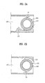
- FIG. 2A illustrates a section across a line I-I in FIG. 1;
- FIG. 2B illustrates a section across a line II-II in FIG. 1;
- FIG. 3 illustrates a plan view showing an air flow in a heat exchange operation of a ventilating system in accordance with a first preferred embodiment of the present invention, schematically;
- FIG. 4 illustrates a plan view showing an air flow in a bypass operation of a ventilating system in accordance with a first preferred embodiment of the present invention, schematically;
- FIG. 5 illustrates a plan view of a ventilating system in accordance with a second preferred embodiment of the present invention, schematically.
- FIGS. 6A and 6B illustrate sections each showing another structure of a fan mounted on the ventilating system of the present invention.
- FIGS. 1 ⁇ 4 illustrates a ventilating system in accordance with a first preferred embodiment of the present invention, including a case 100 having an air supply flow passage 110 and an air discharge passage 120 formed therein to cross each other.
- the air supply flow passage 110 includes a first inlet 110i for drawing outdoor air, a first outlet 110e for discharging the air, and the air discharge flow passage 120 includes a second inlet 120i for drawing room air, and a second outlet 120e for discharging the air to an outside of the room.
- the case 100 there is a fan 400 for drawing outdoor air into the case 100, and discharging the outdoor air to the room, and drawing room air into the case 100, and discharging the room air to an outside of the room.
- the fan 400 is mounted both in the air supply air passage 110 and the air discharge flow passage 120. That is, referring to FIG. 1, the fan 400 has one side mounted in the air supply flow passage 110, and the other side mounted in the air discharge flow passage 120.
- the fan 400 draws air in a circumferential direction and discharges in a circumferential direction, to have a shape like a sirocco fan.
- One motor 250 is coupled to a shaft of the fan 400. That is, driving the fan 400 with the motor 250 enables both an air supply mode and an air discharge mode.
- blades 410 of the fan 400 have straight line sections.
- the blades 410 may be different shapes.
- the blades 410 may have sections curved in directions opposite to the air supply flow passage 110 and the air discharge flow passages 120.
- the direction of the curves of the blades 410 are formed such that air can be drawn from an outside of the room into the case 100 in the case of the air supply mode, and air can be drawn from the room into the case 100 in the case of the air discharge mode.
- the case 100 there is a heat exchanger 200 for making the outdoor air and the room air to cross, and heat exchange, with each other.
- a heat exchanger 200 for making the outdoor air and the room air to cross, and heat exchange, with each other.
- first damper 111 in the air supply flow passage 110 for controlling flow of the outdoor air flowing through the air supply flow passage 110.
- second damper 122 in the air discharge flow passage 120 for controlling flow of the air flowing through the air discharge flow passage 120.
- the first damper 111 and the second damper 122 may be mounted between the heat exchanger 200 and the fan 400, and the second damper 122 may also be mounted between the heat exchanger 200 and the fan 400.
- first bypass 310 provided to the case 100.
- the first bypass 310 is spaced from the air supply flow passage 110, so that the air bypasses the heat exchanger 200 in the case 100.
- first partition wall 181 between the first bypass 310 and the air supply flow passage 110 for separating the first bypass 310 from the air supply flow passage 110.
- first damper 313 mounted to the first bypass 310, for controlling flow of the outdoor air.
- first filter 141 in the air supply flow passage 110 for filtering foreign matters from the outdoor air
- second filter 142 in the first bypass 310 for filtering foreign matters from the outdoor air.
- Both the first filter 141 and the second filter 142 are mounted between the heat exchanger 200 and the fan 400. Though not shown, both the first filter 141 and the second filter 142 may be mounted tilted in the case 100.
- the second bypass 320 is spaced from the air discharge flow passage 120. That is, as shown in FIG. 1, there us a second partition wall 182 between the second bypass 320 and the air discharge flow passage 120, for separating the second bypass 320 from the air discharge flow passage 120.
- damper 324 in the second bypass 320, for controlling room air flowing through the second bypass 320.
- both the air supply flow passage 110 and the air discharge flow passage 120 have air guides 131 on one of upper, and lower sides of the fan 400 for guiding flow of the air, respectively.
- the air supply flow passage 110 and the air discharge flow passage 120 have stabilizers 133 on one of upper and lower sides of the fan 400 opposite to the air guides 131 for preventing the air from flowing in a reverse direction.
- the air guides 131 have curved surfaces for smooth flow of air when the air is introduced into the air supply flow passage 110 and the air discharge flow passage 120, respectively.
- Both ends of each of the first bypass 310 and the second bypass 320 are opened.
- the ventilating system in accordance with a first preferred embodiment of the present invention is operated in the air supply mode, or in the air discharge mode, which will be described in more detail.
- the ventilating system is operated in the air supply mode, or in the air discharge mode, which will be described in more detail.
- the ventilating system is operated in the air supply mode.
- the fan 400 is driven in a state the first damper 111 is opened. Then, outdoor air is drawn into the air supply flow passage 110 through the first inlet 110i by a suction force of the fan 400. Then, the air is discharged to the room through the first outlet 110e after passed through the heat exchanger 200 and the first filter 141. When the air passes through the first filter 141, foreign matters are filtered from the outdoor air by the first filter 141. Thus, cleaned outdoor air is supplied to the room through above steps.
- the fan 400 is driven in a state the second damper 122 is opened. Upon putting the fan 400 into operation, the outdoor air is drawn into the case 100 through the second inlet 120i of the air discharge duct 113. Then, the air is discharged to an outside of the room through the second outlet 120e after passed through the heat exchanger 200.
- both the first damper 111 and the second damper 122 are driven, to close the air supply flow passage 110 and the air discharge flow passage 120, and the fan 400 is driven, so that outdoor air is drawn through the first bypass 310 and discharged to the room through the first outlet 110e, and the room air is drawn into the second bypass 320 through the second inlet 120i, and discharged to an outside of the room through the second outlet 120e. That is, the room air and the outdoor air flow through the case 100 without passing through the heat exchanger 200.
- FIG. 5 illustrates a plan view of a ventilating system in accordance with a second preferred embodiment of the present invention, schematically.
- the ventilating system in accordance with a second preferred embodiment of the present invention is substantially the same with the ventilating system in accordance with a first preferred embodiment of the present invention, except that, while the ventilating system in accordance with a first preferred embodiment of the present invention has a fan 400 crossing the air supply flow passage 110 and the air discharge flow passage 120 at the same time, the ventilating system in accordance with a second preferred embodiment of the present invention has two fans 551 and 552 in the air supply flow passage 110 and the air discharge flow passage 120, respectively.
- a motor 580 is mounted between the first fan 551 and the second fan 552.
- a plurality of louvers may be attached to the first inlet 110i, the first outlet 110e, the second inlet 120i, and the second outlet 120e, for opening/closing the inlets 110i and 120i, and outlets 110e, and 120e.
- the ventilating system of the present invention can introduce outdoor air into the room or discharge room air to an outside of the room by using one fan.
- the first bypass 310 and the second bypass 320 permit to supply and discharge of air without passing through the heat exchanger according to cases. Accordingly, the present invention can provide a ventilating system that is smaller and of which cost is low.
- the filter provided to the ventilating system additionally can perform an air cleaning function. Therefore, air with an appropriate temperature can be supplied to the room even in winter, and a comfortable room environment can be provided by providing cleaned air always.
Landscapes
- Engineering & Computer Science (AREA)
- Chemical & Material Sciences (AREA)
- Combustion & Propulsion (AREA)
- Mechanical Engineering (AREA)
- General Engineering & Computer Science (AREA)
- Health & Medical Sciences (AREA)
- General Health & Medical Sciences (AREA)
- Otolaryngology (AREA)
- Pulmonology (AREA)
- Ventilation (AREA)
- Air Conditioning Control Device (AREA)
- Cooling Or The Like Of Electrical Apparatus (AREA)
Applications Claiming Priority (1)
| Application Number | Priority Date | Filing Date | Title |
|---|---|---|---|
| KR1020050012304A KR100628078B1 (ko) | 2005-02-15 | 2005-02-15 | 환기시스템 |
Publications (2)
| Publication Number | Publication Date |
|---|---|
| EP1701101A2 true EP1701101A2 (de) | 2006-09-13 |
| EP1701101A3 EP1701101A3 (de) | 2007-10-24 |
Family
ID=36337641
Family Applications (1)
| Application Number | Title | Priority Date | Filing Date |
|---|---|---|---|
| EP05010211A Withdrawn EP1701101A3 (de) | 2005-02-15 | 2005-05-11 | Lüftungssystem |
Country Status (4)
| Country | Link |
|---|---|
| US (1) | US7575044B2 (de) |
| EP (1) | EP1701101A3 (de) |
| KR (1) | KR100628078B1 (de) |
| CN (1) | CN1821669A (de) |
Cited By (4)
| Publication number | Priority date | Publication date | Assignee | Title |
|---|---|---|---|---|
| EP2175140A1 (de) * | 2008-10-13 | 2010-04-14 | LTG Aktiengesellschaft | Querstromventilator, Lüftungsgerät mit Querstromventilator und Verfahren zur Lüftung eines Raumes mittels eines Querstromventilators |
| CN101832613A (zh) * | 2010-05-11 | 2010-09-15 | 林勇 | 一种单电机热回收换气装置 |
| EP3032184A1 (de) * | 2014-12-09 | 2016-06-15 | Halton OY | Luftzufuhrelement |
| EP3708921A1 (de) * | 2019-03-13 | 2020-09-16 | Vero Duco N.V. | Gebäude mit bedarfsgesteuertem wärmeaustauschsystem zur belüftung, wärmeaustauschbelüftungssystem und wärmeaustauschsystem |
Families Citing this family (30)
| Publication number | Priority date | Publication date | Assignee | Title |
|---|---|---|---|---|
| KR100680622B1 (ko) | 2005-12-08 | 2007-02-08 | 삼성전자주식회사 | 환기기능을 갖는 공기청정기 |
| NL1032801C2 (nl) * | 2006-11-02 | 2008-05-06 | Johannes Dirk Mooij | Systeem voor het koppelen van twee naast elkaar geplaatste warmtewisselaars en daarbij toe te passen koppeleenheid. |
| JP5061642B2 (ja) * | 2007-02-23 | 2012-10-31 | ダイキン工業株式会社 | 空調換気装置 |
| JP4311489B2 (ja) * | 2007-06-12 | 2009-08-12 | ダイキン工業株式会社 | 調湿装置 |
| JP5202441B2 (ja) * | 2009-05-27 | 2013-06-05 | 三菱電機株式会社 | 熱交換換気装置 |
| JP5333084B2 (ja) * | 2009-09-09 | 2013-11-06 | パナソニック株式会社 | 熱交換機器 |
| KR100984118B1 (ko) * | 2009-12-08 | 2010-09-28 | 현대건설주식회사 | 외기냉방 겸용 전열 교환 폐열회수 환기유니트 |
| WO2012023686A1 (ko) * | 2010-08-18 | 2012-02-23 | 현대건설 주식회사 | 외기냉방기능을 가진 폐열회수 환기시스템의 제어방법 및 그 장치 |
| KR101221240B1 (ko) | 2010-09-29 | 2013-01-11 | 현대건설주식회사 | 외기냉방기능을 가진 폐열회수 환기시스템의 제어방법 |
| US10184684B2 (en) * | 2010-08-26 | 2019-01-22 | Richard S Kurelowech | Heat recovery and demand ventilation system |
| JP5845389B2 (ja) * | 2011-03-14 | 2016-01-20 | パナソニックIpマネジメント株式会社 | 熱交換形換気装置 |
| EP2551607B1 (de) * | 2011-07-28 | 2018-10-17 | LG Electronics Inc. | Lüftungsgerät |
| KR101149815B1 (ko) * | 2012-01-19 | 2012-05-24 | 은성화학(주) | 전열교환 환기유니트 |
| JP5382154B2 (ja) * | 2012-02-10 | 2014-01-08 | ダイキン工業株式会社 | 換気装置 |
| KR101167864B1 (ko) * | 2012-02-17 | 2012-07-24 | 정수이엔지 주식회사 | 실내공기 순환용 급배기 장치 |
| JP5814844B2 (ja) * | 2012-03-26 | 2015-11-17 | 三菱電機株式会社 | 熱交換換気システム |
| JP2014092333A (ja) * | 2012-11-06 | 2014-05-19 | Mitsubishi Electric Corp | 熱交換換気装置 |
| US10775071B2 (en) * | 2013-01-04 | 2020-09-15 | Carrier Corporation | Energy recovery ventilator |
| JP6426353B2 (ja) * | 2014-02-24 | 2018-11-21 | 三菱電機株式会社 | 熱交換換気装置 |
| JP6315555B2 (ja) * | 2014-02-24 | 2018-04-25 | 三菱電機株式会社 | 熱交換換気装置 |
| TWI558954B (zh) * | 2014-09-22 | 2016-11-21 | 建準電機工業股份有限公司 | 具室內外溫差調節功能的氣流交換裝置 |
| FR3026476A1 (fr) * | 2014-09-25 | 2016-04-01 | Commissariat Energie Atomique | Systeme d'echangeur thermique a performances et compacite ameliorees |
| JP2016070534A (ja) * | 2014-09-29 | 2016-05-09 | パナソニックIpマネジメント株式会社 | 熱交換形換気装置 |
| WO2017152420A1 (zh) * | 2016-03-11 | 2017-09-14 | 曾国辉 | 热回收新风机 |
| CN109477657A (zh) * | 2016-03-31 | 2019-03-15 | 工业设计实验室股份有限公司 | 紧凑型热回收通风系统 |
| DE102018003346A1 (de) * | 2018-01-02 | 2019-07-04 | Kampmann Gmbh | Vorrichtung zum Lüften von Räumen |
| KR102302356B1 (ko) * | 2021-02-01 | 2021-09-15 | 주식회사 에코에어시스템 | 단일 필터유닛을 적용한 음양압 환경 조성용 공기 청정 순환 장치 |
| US20240060661A1 (en) * | 2022-08-19 | 2024-02-22 | Lg Electronics Inc. | Ventilation apparatus |
| KR102699419B1 (ko) * | 2022-08-19 | 2024-08-28 | 엘지전자 주식회사 | 환기 장치 |
| CN119195622A (zh) * | 2024-11-28 | 2024-12-27 | 常州市宇轩电子有限公司 | 一种蜂窝状截止波导通风窗 |
Family Cites Families (24)
| Publication number | Priority date | Publication date | Assignee | Title |
|---|---|---|---|---|
| US34151A (en) * | 1862-01-14 | Means for covering and repairing- iron ships and other navigable | ||
| US3261397A (en) * | 1963-12-24 | 1966-07-19 | Mclean Engineering Lab | Combined cooling and heating apparatus |
| DK116759B (da) * | 1967-01-30 | 1970-02-09 | Nordisk Ventilator | Ventilator til ventilation af bygninger, f. eks. stalde. |
| US3666007A (en) * | 1970-03-17 | 1972-05-30 | Mitsubishi Electric Corp | Apparatus for effecting continuous and simultaneous transfer of heat and moisture between two air streams |
| FR2441132A1 (fr) * | 1978-11-07 | 1980-06-06 | Mitsubishi Electric Corp | Conditionneur d'air simplifie |
| SE8002896L (sv) * | 1980-04-17 | 1981-10-18 | Bahco Ventilation Ab | Vermeatervinningsanordning |
| DE3035672A1 (de) * | 1980-09-22 | 1982-05-19 | Enig Energieberatung Innovation Gmbh, 6300 Giessen | Raumlueftungsgeraet fuer den einbau in fenster oder mauern |
| JPS57122291A (en) * | 1981-01-21 | 1982-07-30 | Toshiba Corp | Heat exchanging apparatus |
| US4563126A (en) | 1981-03-18 | 1986-01-07 | Hitachi, Ltd. | Casing of blower and ventilating fan utilizing the casing |
| JPS5899626A (ja) * | 1981-12-09 | 1983-06-14 | Matsushita Electric Ind Co Ltd | 同時吸排気換気扇 |
| DE3631942A1 (de) * | 1986-09-19 | 1988-04-07 | Siemens Ag | Radialventilator |
| FI83134C (fi) * | 1987-12-18 | 1991-05-27 | Ilmaterae Oy | Foerfarande och anordning foer reglering av luftstroemmar och tryck i luftkonditionering. |
| US5000253A (en) * | 1988-03-31 | 1991-03-19 | Roy Komarnicki | Ventilating heat recovery system |
| CA2059195C (en) * | 1992-01-10 | 1995-01-31 | Rene Morissette | Defrostable ventilation system |
| US5816315A (en) * | 1995-09-13 | 1998-10-06 | Nautica Dehumidifiers, Inc. | Plate-type crossflow air-to-air heat exchanger having dual pass cooling |
| US5943878A (en) * | 1998-05-22 | 1999-08-31 | American Standard Inc. | Tangential fan scroll and discharged diffuser design |
| US6695038B2 (en) * | 1999-09-02 | 2004-02-24 | Advanced Rotary Systems, Llc | Heat exchanger type fan |
| DE10010832C1 (de) * | 2000-03-09 | 2001-11-22 | Krantz Tkt Gmbh | Vorrichtung zur Temperierung und/oder Belüftung eines Raumes |
| JP2003014272A (ja) * | 2001-06-29 | 2003-01-15 | Sanyo Electric Co Ltd | 空調換気扇 |
| HK1037473A2 (en) * | 2001-09-20 | 2002-03-15 | 杨渠旺 | An air-ventilator with high efficiency thermal exchanger and air filter |
| CN2559812Y (zh) | 2002-04-29 | 2003-07-09 | 付东 | 双向换气风扇 |
| CN1206483C (zh) | 2003-04-17 | 2005-06-15 | 上海交通大学 | 节能自动换气机 |
| KR100628205B1 (ko) * | 2003-05-28 | 2006-09-26 | 엘지전자 주식회사 | 환기겸용 공조시스템 및 그 제어방법 |
| KR100546665B1 (ko) | 2003-08-22 | 2006-01-26 | 엘지전자 주식회사 | 공기 청정기 |
-
2005
- 2005-02-15 KR KR1020050012304A patent/KR100628078B1/ko not_active Expired - Fee Related
- 2005-05-11 EP EP05010211A patent/EP1701101A3/de not_active Withdrawn
- 2005-05-19 US US11/132,212 patent/US7575044B2/en active Active
- 2005-05-30 CN CNA2005100746056A patent/CN1821669A/zh active Pending
Cited By (7)
| Publication number | Priority date | Publication date | Assignee | Title |
|---|---|---|---|---|
| EP2175140A1 (de) * | 2008-10-13 | 2010-04-14 | LTG Aktiengesellschaft | Querstromventilator, Lüftungsgerät mit Querstromventilator und Verfahren zur Lüftung eines Raumes mittels eines Querstromventilators |
| DE102008052823B4 (de) * | 2008-10-13 | 2016-07-07 | Ltg Aktiengesellschaft | Querstromventilator, Lüftungsgerät mit Querstromventilator und Verfahren zur Lüftung eines Raumes mittels eines Querstromventilators |
| CN101832613A (zh) * | 2010-05-11 | 2010-09-15 | 林勇 | 一种单电机热回收换气装置 |
| CN101832613B (zh) * | 2010-05-11 | 2012-06-27 | 林勇 | 一种单电机热回收换气装置 |
| EP3032184A1 (de) * | 2014-12-09 | 2016-06-15 | Halton OY | Luftzufuhrelement |
| EP3708921A1 (de) * | 2019-03-13 | 2020-09-16 | Vero Duco N.V. | Gebäude mit bedarfsgesteuertem wärmeaustauschsystem zur belüftung, wärmeaustauschbelüftungssystem und wärmeaustauschsystem |
| NL2022733B1 (en) * | 2019-03-13 | 2020-09-18 | Vero Duco Nv | Building With Demand-Controlled Heat Exchange System For Ventilation, Heat Exchange Ventilation System and Heat Exchange System |
Also Published As
| Publication number | Publication date |
|---|---|
| KR100628078B1 (ko) | 2006-09-26 |
| US7575044B2 (en) | 2009-08-18 |
| EP1701101A3 (de) | 2007-10-24 |
| KR20060091428A (ko) | 2006-08-21 |
| US20060199510A1 (en) | 2006-09-07 |
| CN1821669A (zh) | 2006-08-23 |
Similar Documents
| Publication | Publication Date | Title |
|---|---|---|
| US7575044B2 (en) | Ventilating system | |
| CN113811720B (zh) | 具有动态智能空气管理系统的ptac单元 | |
| KR100651879B1 (ko) | 환기시스템 | |
| US20060199511A1 (en) | Ventilating system | |
| CN212511454U (zh) | 风机组件、新风装置、空调室内机及空调器 | |
| KR101951569B1 (ko) | 무덕트형 공기청정 환기장치 | |
| US20050287945A1 (en) | Ventilating system | |
| US7331853B2 (en) | Ventilating system | |
| CN105605671A (zh) | 空调设备 | |
| CN213713240U (zh) | 空气处理模块、空调室内机及空调器 | |
| JP2005043032A (ja) | 空気清浄機 | |
| EP1600705A2 (de) | Lüftungsanlage | |
| JP3783015B2 (ja) | 換気機能付き空気清浄装置 | |
| KR100577205B1 (ko) | 환기시스템 | |
| JP3843273B2 (ja) | 空気清浄機 | |
| KR102193840B1 (ko) | 천장형 공기순환기 | |
| KR100640799B1 (ko) | 공기 청정 겸용 환기장치 | |
| US20060199509A1 (en) | Ventilating system | |
| KR100531087B1 (ko) | 환기기능을 구비한 공기청정기 | |
| EP1701106A2 (de) | Lüftungssystem | |
| KR20070051220A (ko) | 환기장치 및 환기장치의 제어방법 | |
| KR20060037584A (ko) | 환기장치 | |
| KR100895136B1 (ko) | 환기시스템 | |
| KR102193841B1 (ko) | 천장형 공기순환기 | |
| KR100624708B1 (ko) | 환기장치 |
Legal Events
| Date | Code | Title | Description |
|---|---|---|---|
| PUAI | Public reference made under article 153(3) epc to a published international application that has entered the european phase |
Free format text: ORIGINAL CODE: 0009012 |
|
| AK | Designated contracting states |
Kind code of ref document: A2 Designated state(s): AT BE BG CH CY CZ DE DK EE ES FI FR GB GR HU IE IS IT LI LT LU MC NL PL PT RO SE SI SK TR |
|
| AX | Request for extension of the european patent |
Extension state: AL BA HR LV MK YU |
|
| PUAL | Search report despatched |
Free format text: ORIGINAL CODE: 0009013 |
|
| AK | Designated contracting states |
Kind code of ref document: A3 Designated state(s): AT BE BG CH CY CZ DE DK EE ES FI FR GB GR HU IE IS IT LI LT LU MC NL PL PT RO SE SI SK TR |
|
| AX | Request for extension of the european patent |
Extension state: AL BA HR LV MK YU |
|
| AKX | Designation fees paid | ||
| STAA | Information on the status of an ep patent application or granted ep patent |
Free format text: STATUS: THE APPLICATION IS DEEMED TO BE WITHDRAWN |
|
| 18D | Application deemed to be withdrawn |
Effective date: 20080425 |
|
| REG | Reference to a national code |
Ref country code: DE Ref legal event code: 8566 |