EP1701156A1 - Vorrichtung zur Prüfung eines Prüflings auf Oberflächenfehler mittels Magnetisierungsmittel und mittels Induktionssonden als Meßsensoren - Google Patents
Vorrichtung zur Prüfung eines Prüflings auf Oberflächenfehler mittels Magnetisierungsmittel und mittels Induktionssonden als Meßsensoren Download PDFInfo
- Publication number
- EP1701156A1 EP1701156A1 EP06004837A EP06004837A EP1701156A1 EP 1701156 A1 EP1701156 A1 EP 1701156A1 EP 06004837 A EP06004837 A EP 06004837A EP 06004837 A EP06004837 A EP 06004837A EP 1701156 A1 EP1701156 A1 EP 1701156A1
- Authority
- EP
- European Patent Office
- Prior art keywords
- magnetic flux
- yoke legs
- flux conductor
- gap
- test piece
- Prior art date
- Legal status (The legal status is an assumption and is not a legal conclusion. Google has not performed a legal analysis and makes no representation as to the accuracy of the status listed.)
- Granted
Links
- 238000012360 testing method Methods 0.000 title claims abstract description 33
- 239000000523 sample Substances 0.000 title claims abstract description 20
- 230000006698 induction Effects 0.000 title claims abstract description 19
- 230000007547 defect Effects 0.000 title claims description 6
- 230000005291 magnetic effect Effects 0.000 claims abstract description 35
- 230000004907 flux Effects 0.000 claims abstract description 32
- 230000017525 heat dissipation Effects 0.000 claims abstract description 6
- 238000001816 cooling Methods 0.000 claims abstract description 5
- 239000000843 powder Substances 0.000 claims abstract description 5
- 239000004020 conductor Substances 0.000 claims description 17
- 230000005284 excitation Effects 0.000 claims description 5
- 239000002131 composite material Substances 0.000 claims description 4
- 239000002826 coolant Substances 0.000 claims description 3
- 239000000463 material Substances 0.000 abstract description 2
- 150000001875 compounds Chemical class 0.000 abstract 1
- 230000005294 ferromagnetic effect Effects 0.000 abstract 1
- 238000004804 winding Methods 0.000 description 5
- 230000005415 magnetization Effects 0.000 description 3
- 238000000265 homogenisation Methods 0.000 description 2
- 238000004519 manufacturing process Methods 0.000 description 2
- 238000005096 rolling process Methods 0.000 description 2
- 229910000831 Steel Inorganic materials 0.000 description 1
- 230000006978 adaptation Effects 0.000 description 1
- 239000003795 chemical substances by application Substances 0.000 description 1
- 238000001514 detection method Methods 0.000 description 1
- 230000000694 effects Effects 0.000 description 1
- 238000000227 grinding Methods 0.000 description 1
- 239000012535 impurity Substances 0.000 description 1
- 238000000034 method Methods 0.000 description 1
- 238000003801 milling Methods 0.000 description 1
- 230000002093 peripheral effect Effects 0.000 description 1
- 230000001681 protective effect Effects 0.000 description 1
- 239000010959 steel Substances 0.000 description 1
Images
Classifications
-
- H—ELECTRICITY
- H01—ELECTRIC ELEMENTS
- H01F—MAGNETS; INDUCTANCES; TRANSFORMERS; SELECTION OF MATERIALS FOR THEIR MAGNETIC PROPERTIES
- H01F3/00—Cores, Yokes, or armatures
- H01F3/08—Cores, Yokes, or armatures made from powder
-
- G—PHYSICS
- G01—MEASURING; TESTING
- G01N—INVESTIGATING OR ANALYSING MATERIALS BY DETERMINING THEIR CHEMICAL OR PHYSICAL PROPERTIES
- G01N27/00—Investigating or analysing materials by the use of electric, electrochemical, or magnetic means
- G01N27/72—Investigating or analysing materials by the use of electric, electrochemical, or magnetic means by investigating magnetic variables
- G01N27/82—Investigating or analysing materials by the use of electric, electrochemical, or magnetic means by investigating magnetic variables for investigating the presence of flaws
- G01N27/90—Investigating or analysing materials by the use of electric, electrochemical, or magnetic means by investigating magnetic variables for investigating the presence of flaws using eddy currents
- G01N27/9013—Arrangements for scanning
- G01N27/9026—Arrangements for scanning by moving the material
-
- G—PHYSICS
- G01—MEASURING; TESTING
- G01N—INVESTIGATING OR ANALYSING MATERIALS BY DETERMINING THEIR CHEMICAL OR PHYSICAL PROPERTIES
- G01N27/00—Investigating or analysing materials by the use of electric, electrochemical, or magnetic means
- G01N27/72—Investigating or analysing materials by the use of electric, electrochemical, or magnetic means by investigating magnetic variables
- G01N27/82—Investigating or analysing materials by the use of electric, electrochemical, or magnetic means by investigating magnetic variables for investigating the presence of flaws
- G01N27/90—Investigating or analysing materials by the use of electric, electrochemical, or magnetic means by investigating magnetic variables for investigating the presence of flaws using eddy currents
- G01N27/904—Investigating or analysing materials by the use of electric, electrochemical, or magnetic means by investigating magnetic variables for investigating the presence of flaws using eddy currents with two or more sensors
-
- G—PHYSICS
- G01—MEASURING; TESTING
- G01N—INVESTIGATING OR ANALYSING MATERIALS BY DETERMINING THEIR CHEMICAL OR PHYSICAL PROPERTIES
- G01N27/00—Investigating or analysing materials by the use of electric, electrochemical, or magnetic means
- G01N27/72—Investigating or analysing materials by the use of electric, electrochemical, or magnetic means by investigating magnetic variables
- G01N27/82—Investigating or analysing materials by the use of electric, electrochemical, or magnetic means by investigating magnetic variables for investigating the presence of flaws
- G01N27/90—Investigating or analysing materials by the use of electric, electrochemical, or magnetic means by investigating magnetic variables for investigating the presence of flaws using eddy currents
- G01N27/9013—Arrangements for scanning
- G01N27/902—Arrangements for scanning by moving the sensors
Definitions
- the invention relates to a device for testing a test specimen for surface defects by means of magnetizing means for introducing a magnetic flux into the specimen and by means of induction probes as measuring sensors, wherein the induction probes are rotatable about the longitudinally feasible specimen in order to scan it helically.
- Such devices are used to z.
- circular profile such as billets, rods steel pipes or the like to determine while these objects, which may have high temperatures depending on the choice of the manufacturing process, through a production line, such as a rolling mill run.
- Magnetizing agents magnetize the test piece in such a way that near-surface defects produce a leakage flux which can be detected by means of induction probes.
- Errors in and under the surface of a sample cause, e.g. a leakage flux, which is detected by means of the induction probes.
- the output signals of the induction probes are therefore a measure of the impurities and defects in and under the surface of a test object.
- the induction probes for error detection are arranged close to the circumferential wall of the test object.
- the induction probes may be capable of detecting stray magnetic fluxes or designed as eddy current sensors.
- the induction probes can also work on the basis of magnetoresistive effects.
- This Rotierkopf is essentially composed of a housing with a hollow shaft for performing a test specimen and a rotating part, on the induction probes, z. As eddy current sensors are attached. Drive means are further provided to produce the orbital motion of the rotating part.
- the drive wheel of a drive motor is connected via a drive belt with a rigidly seated on the hollow shaft drive wheel.
- At the front and rear end of the Hollow shaft sits each a protective bushing, through which the specimen is guided.
- a rotating disc is rigidly connected to the hollow shaft.
- two levers are pivotally mounted, each carrying an induction probe.
- a magnetic flux is passed in the longitudinal direction by means of a magnetizing coil comprising it and by means of Magnetflußleiter.
- Magnetflußleiter serve parts of the housing and the hollow shaft.
- a homogenization ring made of a magnetically conductive material is provided for the homogenization of the magnetic field in the test area.
- Out DE OS 29 05 399 is another such device known.
- a test object can be guided by a cylindrical element which is rotatable about its longitudinal axis.
- a plurality of induction probes are attached close to the peripheral wall, which are formed as eddy current error detector coils.
- the output signals of the coils are evaluated in a signal detector circuit.
- An alternating current signal of fixed frequency is applied to the coils, which generates an eddy current just below the surface of the test object. Errors in the device under test change the coil impedance.
- the magnetic flux extends in the test specimen in the longitudinal direction and below the mantle surface of the specimen.
- the specified known devices are subject to the first disadvantage that they are not fast and inexpensive to different dimensions, in particular those of the cross sections, the specimens are adaptable.
- a second disadvantage is to be seen in the insufficient heat dissipation, which sets narrow limits as a third disadvantage of the life of the device and finally limits the magnetization performance as a fourth disadvantage.
- the shape of the coil core used in the cited devices can be changed in isolated wound band cores only at great expense.
- the invention solves this problem with the features specified in claim 1, characterized in that at least two yoke legs with their gap ends forming a gap, through which the specimen is feasible that sits on each column end an exciter coil that the excitation coils are oppositely poled that the outer ends of the yoke legs opposite the gap ends are connected together by means of a magnetic flux conductor, so that the magnetic flux runs perpendicular to the longitudinal direction through the test object.
- the magnetic flux guide can be designed, for example, in a triangular, quadrilateral or preferably annular manner.
- the outer ends of the yoke legs can z. B. rest on the magnetic flux conductor. Alternatively, the magnetic flux conductor can rest on the outer ends of the yoke legs. About the magnetic flux conductor can be very well dissipate the heat loss generated by reversal.
- the device according to the invention is therefore suitable for high magnetization powers and is characterized by a long service life.
- the yoke legs are radially movable in the radial direction and lockable, but the contact with the magnetic flux conductor is always maintained regardless of the position.
- the induction probes sit in a further embodiment of the invention on levers which are pivotally mounted about an axis on Magnetflußleiter.
- a further embodiment of the invention provides for fastening the preferably annular magnetic flux conductor with good thermal conductivity to a rotatable rotating disk on which cooling fins or the like can be provided for better heat dissipation.
- a rotary drive is provided to rotate the rotating disk.
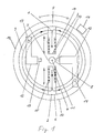
- two yoke legs 1 and 2 are arranged opposite each other standing so that between their opposite ends, the column ends 3 and 4, a gap 7 is formed, through which a specimen 8 is guided perpendicular to the plane.
- On the gap ends 3 and 4 of the yoke legs 1 and 2 sit energizing windings 14 and 15.
- the gap ends 3 and 4 opposite outer ends 5 and 6 are connected via an annular magnetic flux conductor 9, which sits on a rotating disk 10.
- On the magnetic flux guide 9 two pivotable about an axis 17 levers 12 are arranged, on each of which an induction probe 13 is seated.
- the yoke legs 1 and 2 in the direction of the double arrows are slidably mounted and fixed on the annular magnetic flux guide 9.
- the yoke legs 1 and 2 and the magnetic flux guide 9 are preferably made of a powder composite material. On the invisible back of the rotating disk 10 are not visible for better heat dissipation in the figure 1 coolant, z. B. cooling fins arranged.
- the rotating disk 10 is rotated with the Magnetflußleiter 9, the yoke legs 1 and 2 and the levers 12 with the induction probes 13 in the arrow direction about the longitudinal axis 11 of the specimen 8 by means of a rotation only symbolically shown rotary drive 19 while the examinee 8, z. B. a rod in a rolling mill, is guided perpendicular to the rotational plane of the rotary disk 10. In this way, the test piece 8 is scanned helically to check its quality.
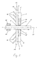
- FIG. 2 shows a longitudinal section through the basic structure of the embodiment shown in Figure 1.
- the specimen 8 is guided in the direction of the arrow through the gap 7 by means of a feed device 18 shown schematically in the arrow direction, while the rotating disk 10 with the yoke legs 1 and 2 and the Magnetflußleiter 9 about the longitudinal axis 11 of the specimen 8 from the sake of clarity only symbolically shown rotary drive 19 driven rotated.
- a feed device 18 shown schematically in the arrow direction
- the invention is particularly suitable for testing of test specimens by means of high-energy magnetic alternating fields, because the high heat losses generated in this method are sufficiently dissipated in the inventive device.
Landscapes
- Chemical & Material Sciences (AREA)
- Analytical Chemistry (AREA)
- General Physics & Mathematics (AREA)
- Chemical Kinetics & Catalysis (AREA)
- Electrochemistry (AREA)
- Physics & Mathematics (AREA)
- Health & Medical Sciences (AREA)
- Pathology (AREA)
- Biochemistry (AREA)
- Life Sciences & Earth Sciences (AREA)
- General Health & Medical Sciences (AREA)
- Immunology (AREA)
- Engineering & Computer Science (AREA)
- Power Engineering (AREA)
- Investigating Or Analyzing Materials By The Use Of Magnetic Means (AREA)
- Magnetic Treatment Devices (AREA)
Abstract
Description
- Die Erfindung betrifft eine Vorrichtung zur Prüfung eines Prüflings auf Oberflächenfehler mittels Magnetisierungsmittel zum Einleiten eines Magnetflusses in den Prüfling und mittels Induktionssonden als Meßsensoren, wobei die Induktionssonden um den in Längsrichtung führbaren Prüfling drehbar sind, um ihn schraubenförmig abzutasten.
- Derartige Vorrichtungen werden eingesetzt, um z. B. Oberflächenfehler an metallischen Gegenständen kreisförmigen Profils, wie Knüppel, Stangen Stahlrohre oder dergleichen zu ermitteln, während diese Gegenstände, die je nach Wahl des Fertigungsverfahrens hohe Temperaturen aufweisen können, durch eine Fertigungsstraße, beispielsweise eine Walzstraße, laufen.
- Magnetisierungsmittel magnetisieren den Prüfling derart, daß oberflächennahe Fehler einen Streufluß erzeugen, der mittels Induktionssonden detektiert werden kann. Fehler in und unter der Oberfläche eines Prüflings verursachen z.B. einen Streufluß, der mittels der Induktionssonden detektiert wird. Die Ausgangssignale der Induktionssonden sind daher ein Maß für die Unreinheiten und Fehler in und unter der Oberfläche eines Prüflings. Die Induktionssonden zur Fehlererkennung sind nahe der Umfangswandung des Prüflings angeordnet. Die Induktionssonden können geeignet sein, magnetische Streuflüsse zu detektieren, oder als Wirbelstromsensorcn ausgelegt sein. Die Induktionssonden können auch auf Basis magnetoresistiver Effekte funktionieren.
- In
DE 39 37 261 C2 ist eine derartige Vorrichtung, ein Rotierkopf, zum Abtasten von metallischem Prüfgut beschrieben. Dieser Rotierkopf ist im wesentlichen aus einem Gehäuse mit einer Hohlwelle zum Durchführen eines Prüflings und einem Rotierteil aufgebaut, an dem Induktionssonden, z. B. Wirbelstromgeber, befestigt sind. Es sind ferner Antriebsmittel vorgesehen, um die Umlaufbewegung des Rotierteils zu erzeugen. Das Antriebsrad eines Antriebsmotors ist über einen Treibriemen mit einem starr auf der Hohlwelle sitzenden Treibrad verbunden. Am vorderen und hinteren Ende der Hohlwelle sitzt je eine Schutzbuchse, durch welche der Prüfling geführt wird. Eine Rotierscheibe ist starr mit der Hohlwelle verbunden. Auf der Hohlwelle sind zwei Hebel schwenkbar befestigt, welche je eine Induktionssonde tragen. In den Prüfling wird ein Magnetfluß in Längsrichtung mittels einer ihn umfassenden Magnetisierungsspule und mittels Magnetflußleiter geleitet. Als Magnetflußleiter dienen Teile des Gehäuses und die Hohlwelle. Zur Homogenisierung des Magnetfeldes im Prüfungsbereich ist ein Homogenisierungsring aus einem magnetisch leitenden Werkstoff vorgesehen. - Aus
DE OS 29 05 399 ist eine weitere derartige Vorrichtung bekannt. Ein Prüfling ist durch ein zylinderförmiges Element führbar, das um seine Längsachse drehbar ist. Am zylindrischen Element sind nahe an dessen Umfangswandung mehrere Induktionssonden befestigt, die als Wirbelstromfehlerdetektorspulen ausgebildet sind. Durch Drehen des zylinderförmigen Elementes und gleichzeitiges Führen des Prüflings in Längsrichtung wird der Prüfling schraubenförmig durch die Spulen abgetastet. Die Ausgangssignale der Spulen werden in einem Signaldetektorkreis ausgewertet. An die Spulen wird ein Wechselstromsignal fester Frequenz gelegt, das kurz unterhalb der Oberfläche des Prüflings einen Wirbelstrom erzeugt. Fehler im Prüfling verändern die Spulenimpedanz. Der Magnetfluß verläuft im Prüfling in Längsrichtung auf und unterhalb der Manteloberfläche des Prüflings. - Die angegebenen bekannten Vorrichtungen sind mit dem ersten Nachteil behaftet, daß sie nicht schnell und kostengünstig an unterschiedliche Abmessungen, insbesondere die der Querschnitte, der Prüflinge anpaßbar sind. Ein zweiter Nachteil ist in der ungenügenden Wärmeabfuhr zu sehen, die als dritten Nachteil der Lebensdauer der Vorrichtung enge Grenzen setzt und schließlich noch als vierten Nachteil die Magnetisierungsleistung begrenzt. Die Form der bei den angeführten Vorrichtungen eingesetzten Spulenkeme läßt sich bei isoliert gewickelten Bandkernen nur unter hohem finanziellen Aufwand verändern.
- Es ist daher Aufgabe der Erfindung, eine Vorrichtung gemäß Oberbegriff des Anspruchs 1 so zu gestalten, daß sie leicht ohne großen Aufwand an unterschiedliche Prüflinge anpaßbar ist und sich durch eine hohe Wärmeabfuhr auszeichnet, um sowohl eine hohe Magnetisierungsleistung als auch Lebensdauer zu erzielen.
- Die Erfindung löst diese Aufgabe mit den im Patentanspruch 1 angegebenen Merkmalen dadurch, daß sich mindestens zwei Jochschenkel mit ihren Spaltenden einen Spalt bildend gegenüberliegen, durch den der Prüfling führbar ist, daß auf jedem Spaltende eine Erregerspule sitzt, daß die Erregerspulen entgegengesetzt gepolt sind, daß die den Spaltenden gegenüberliegenden Außenenden der Jochschenkel mittels eines Magnetflußleiters miteinander verbunden sind, so daß der Magnetfluß senkrecht zur Längsrichtung durch den Prüfling verläuft.
- Der Magnetflußleiter kann beispielsweise drei-, viereckförmig oder vorzugsweise ringförmig gestaltet sein. Durch die erfindungsgemäße Maßnahme, zwei Jochschenkel mit je einer Erregerwicklung so gegeneinander anzuordnen, daß zwischen den sich gegenüberliegenden Enden, den Spaltenden, ein Spalt gebildet wird, und die Außenenden der Jochschenkel über einen Magnetflußleiter miteinander zu verbinden, kann diese Anordnung aus einem Pulververbundwerkstoff preisgünstig hergestellt und an Prüflinge unterschiedlicher Abmessungen angepaßt werden, weil Pulververbundwerkstoffe leicht durch Sägen, Fräsen und Schleifen bearbeitbar sind. Die Außenenden der Jochschenkel können z. B. auf dem Magnetflußleiter aufliegen. Alternativ kann der Magnetflußleiter auf den Außenenden der Jochschenkel aufliegen. Über den Magnetflußleiter läßt sich sehr gut die durch Ummagnetisierung erzeugte Verlustwärme abführen. Die erfindungsgemäße Vorrichtung ist daher für hohe Magnetisierungsleistungen geeignet und zeichnet sich durch eine lange Lebensdauer aus.
- Ausführungsbeispiele und Ausgestaltungen der Erfindung sind in den Unteransprüchen angegeben.
- Um die erfindungsgemäße Vorrichtung an Prüflinge unterschiedlichen Querschnitts anpassen zu können, sind die Jochschenkel strahlenförmig in radialer Richtung verschieb- und feststellbar, wobei jedoch der Kontakt mit dem Magnetflußleiter unabhängig von der Stellung stets erhalten bleibt.
- Die Induktionssonden sitzen bei einer weiteren Ausgestaltung der Erfindung auf Hebeln, die um eine Achse schwenkbar am Magnetflußleiter befestigt sind.
- Ein weiteres Ausführungsbeispiel der Erfindung sieht vor, den vorzugsweise ringförmigen Magnetflußleiter gut wärmeleitend an einer drehbaren Rotierscheibe zu befestigen, an welcher zur besseren Wärmeabfuhr Kühllamellen oder dergleichen vorgesehen sein können. Zum Drehen der Rotierscheibe ist ein Rotationsantrieb vorgesehen.
- Am Magnetflußleiter können mehr als zwei Jochschenkel mit je einer Erregerwicklung vorgesehen sein
- Die Erfindung wird nun an Hand der Figuren näher beschrieben und erläutert.
- In der Zeichnung zeigen:
- Fig. 1
- den prinzipiellen Aufbau eines Ausführungsbeispieles der Erfindung in Draufsicht und
- Fig. 2
- einen Längsschnitt des prinzipiellen Aufbaus des in Figur 1 gezeigten Ausführungsbeispieles der Erfindung.
- In den Figuren 1 und 2 sind zwei Jochschenkel 1 und 2 so einander gegenüber stehend angeordnet, daß zwischen ihren gegenüberliegenden Enden, den Spaltenden 3 und 4, ein Spalt 7 gebildet wird, durch welchen ein Prüfling 8 senkrecht zur Zeichenebene geführt wird. Auf den Spaltenden 3 und 4 der Jochschenkel 1 und 2 sitzen Erregerwicklungen 14 und 15. Die den Spaltenden 3 und 4 gegenüberliegenden Außenenden 5 und 6 sind über einen ringförmigen Magnetflußleiter 9, der auf einer Rotierscheibe 10 sitzt, verbunden. Auf dem Magnetflußleiter 9 sind zwei um eine Achse 17 schwenkbare Hebel 12 angeordnet, auf denen je eine Induktionssonde 13 sitzt. Zur Anpassung an Prüflinge unterschiedlichen Querschnitts sind die Jochschenkel 1 und 2 in Richtung der Doppelpfeile verschiebbar und feststellbar am ringförmigen Magnetflußleiter 9 befestigt.
- Die Jochschenkel 1 und 2 sowie der Magnetflußleiter 9 sind vorzugsweise aus einem Pulververbundwerkstoff hergestellt. Auf der nicht sichtbaren Rückseite der Rotierscheibe 10 sind zur besseren Wärmeabfuhr in der Figur 1 nicht sichtbare Kühlmittel, z. B. Kühllamellen, angeordnet. Zur Prüfung des Prüflings 8 auf Fehler wird die Rotierscheibe 10 mit dem Magnetflußleiter 9 , den Jochschenkeln 1 und 2 und den Hebeln 12 mit den Induktionssonden 13 in Pfeilrichtung um die Längsachse 11 des Prüflings 8 mittels eines der Übersichtlichkeit wegen nur symbolisch dargestellten Rotationsantriebes 19 gedreht, während der Prüfling 8, z. B. eine Stange in einer Walzstraße, senkrecht zur Drehebene der Rotationsscheibe 10 geführt wird. Auf diese Weise wird der Prüfling 8 schraubenförmig abgetastet, um seine Güte zu prüfen.
- Die Figur 2 zeigt einen Längsschnitt durch den prinzipiellen Aufbau des in der Figur 1 abgebildeten Ausführungsbeispieles. Der Prüfling 8 wird in Pfeilrichtung durch den Spalt 7 mittels einer schematisch dargestellten Vorschubeinrichtung 18 in Pfeilrichtung geführt, während gleichzeitig die Rotierscheibe 10 mit den Jochschenkeln 1 und 2 und dem Magnetflußleiter 9 um die Längsachse 11 des Prüflings 8 vom der Übersichtlichkeit wegen nur symbolisch dargestellten Rotationsantrieb 19 angetrieben rotiert. Auf der Rückseite der Rotierscheibe 10 sitzen Kühllamellen 16 zur Kühlung der Jochschenkel 1 und 2 und des Magnetflußleiters 9. - Durch die dargestellte spezielle Gestaltung des Magnetkreises relativ zum Prüfling 8 ergibt sich der entscheidende Vorteil, daß im Falle einer exzentrischen Lage des Prüflings der wirksame Luftspalt zwischen diesem und den Jochen als praktisch konstant und unabhängig von der Drehlage der Rotierscheibe 10 erweist. - Auf diese Weise reduziert sich eine sonst zu beobachtende Amplitudenschwankung des Fehlersignales erheblich.
- Die Erfindung ist insbesondere zur Prüfung von Prüflingen mittels hochenergetischer magnetischer Wechselfelder geeignet, weil die bei diesem Verfahren erzeugten hohen Wärmeverluste ausreichend bei der erfindungsgemäßen Vorrichtung abgeführt werden.
-
- 1
- Jochschenkel
- 2
- Jochschenkel
- 3
- Spaltende
- 4
- Spaltende
- 5
- Außenende
- 6
- Außenende
- 7
- Spalt
- 8
- Prüfling
- 9
- Magnetflußleiter
- 10
- Rotierscheibe
- 11
- Längsachse des Prüflings
- 12
- Hebel
- 13
- Induktionssonde
- 14
- Erregerwicklung
- 15
- Erregerwicklung
- 16
- Kühllamelle
- 17
- Drehachse
- 18
- Vorschubeinrichtung
- 19
- Rotationsantrieb
Claims (14)
- Vorrichtung zur Prüfung eines Prüflings (8) auf Oberflächenfehler mittels Magnetisierungsmittel (1, 2, 9, 14, 15) zum Einleiten eines Magnetflusses in den Prüfling (8) und mittels Induktionssonden (13, 14) als Meßsensoren, dadurch gekennzeichnet, daß sich mindestens zwei Jochschenkel (1, 2) mit ihren Spaltenden (3, 4) einen Spalt (7) bildend gegenüberliegen, durch den der Prüfling (8) führbar ist, daß auf jedem Spaltende (3, 4) eine Erregerspule (14, 15) sitzt, daß die Erregerspulen (14, 15) entgegengesetzt gepolt sind, daß die den Spaltenden (3, 4) gegenüberliegenden Außenenden (5, 6) der Jochschenkel (1, 2) mittels eines Magnetflußleiters (9) miteinander verbunden sind, so daß der Magnetfluß senkrecht zur Längsrichtung durch den Prüfling (8) verläuft.
- Vorrichtung nach Anspruch 1, dadurch gekennzeichnet, daß die Jochschenkel (1, 2) und/oder der Magnetflußleiter (9) aus einem Pulververbundwerkstoff hergestellt sind.
- Vorrichtung nach Anspruch 1 oder 2, dadurch gekennzeichnet, daß der Magnetflußleiter (9) ringförmig gestaltet ist.
- Vorrichtung nach einem der vorangehenden Ansprüche, dadurch gekenzeichnet, daß die Jochschenkel (1, 2) in radialer Richtung verschiebbar und feststellbar sind, um den Spalt (7) an Prüflinge (8) unterschiedlichen Querschnitts anpassen zu können.
- Vorrichtung nach einem der vorangehenden Ansprüche, dadurch gekennzeichnet, daß der Magnetflußleiter (9) mit den Außenenden (4, 5) der Jochschenkel (1, 2) verbunden ist.
- Vorrichtung nach Anspruch 5, dadurch gekennzeichnet, daß der Magnetflußleiter (9) auf den Außenenden (5, 6) der Jochschenkel (1, 2) aufliegt.
- Vorrichtung nach einem der vorangehenden Ansprüche, dadurch gekennzeichnet, daß die Jochschenkel (1, 2) und der Magnetflußleiter (9) auf einer mittels eines Rotationsantriebes (19) drehbaren Rotierscheibe (10) angeordnet sind.
- Vorrichtung nach Anspruch 7, dadurch gekennzeichnet, daß der Magnetflußleiter (9) gut wärmeleitend mit der Rotierscheibe (10) verbunden ist.
- Vorrichtung nach Anspruch 7 oder 8, dadurch gekennzeichnet, daß an der Rotierscheibe (10) Kühlmittel (16) zur Wärmeabgabe an die Umgebung vorgesehen sind.
- Vorrichtung nach Anspruch 9, dadurch gekennzeichnet, daß als Kühlmittel Kühllamellen (16) vorgesehen sind.
- Vorrichtung nach einem der vorangehenden Ansprüche, dadurch gekennzeichnet, daß die Induktionssonden (13) auf schwenkbaren Hebeln (12) sitzen.
- Vorrichtung nach Anspruch 11, dadurch gekennzeichnet, daß die Hebel (12) schwenkbar am Magnetflußleiter (9) befestigt sind.
- Vorrichtung nach einem der vorangehenden Ansprüche, dadurch gekennzeichnet, daß am Magnetflußleiter (9) mehr als zwei Jochschenkel (1, 2) angeordnet sind.
- Vorrichtung nach Anspruch 13, dadurch gekennzeichnet, daß die Jochschenkel (1, 2) in radialer Richtung verschiebbar und feststellbar sind.
Applications Claiming Priority (1)
| Application Number | Priority Date | Filing Date | Title |
|---|---|---|---|
| DE202005003685U DE202005003685U1 (de) | 2005-03-08 | 2005-03-08 | Technische Neuerungen im Magnetkreis des Hochenergiewechselfeldjochs |
Publications (2)
| Publication Number | Publication Date |
|---|---|
| EP1701156A1 true EP1701156A1 (de) | 2006-09-13 |
| EP1701156B1 EP1701156B1 (de) | 2008-05-14 |
Family
ID=35160608
Family Applications (1)
| Application Number | Title | Priority Date | Filing Date |
|---|---|---|---|
| EP06004837A Revoked EP1701156B1 (de) | 2005-03-08 | 2006-03-08 | Vorrichtung zur Prüfung eines Prüflings auf Oberflächenfehler mittels Magnetisierungsmittel und mittels Induktionssonden als Meßsensoren |
Country Status (4)
| Country | Link |
|---|---|
| US (1) | US7242186B2 (de) |
| EP (1) | EP1701156B1 (de) |
| AT (1) | ATE395590T1 (de) |
| DE (2) | DE202005003685U1 (de) |
Families Citing this family (6)
| Publication number | Priority date | Publication date | Assignee | Title |
|---|---|---|---|---|
| DE102005046910B4 (de) * | 2005-09-21 | 2009-03-19 | Technische Universität Ilmenau | Verfahren und Anordnung zur berührungslosen Inspektion bewegter elektrisch leitfähiger Substanzen |
| US8324894B2 (en) * | 2006-12-22 | 2012-12-04 | Arizona Board Of Regents For And On Behalf Of Arizona State University | Resonant linearly polarized eddy current sensor |
| US8264221B2 (en) * | 2009-07-31 | 2012-09-11 | Olympus Ndt | Eddy current probe assembly adjustable for inspecting test objects of different sizes |
| DE102015214232A1 (de) * | 2015-07-28 | 2017-02-02 | Prüftechnik Dieter Busch AG | Sondeneinrichtung, Rotierkopf und Prüfgerät |
| TWI617808B (zh) * | 2017-03-10 | 2018-03-11 | Ceradex Corp | Non-heated flat gas sensing element testing device |
| DE102020200480A1 (de) * | 2020-01-16 | 2021-07-22 | Prüftechnik Dieter Busch GmbH | Sondeneinrichtung mit Biegefeder, Rotierkopf und Prüfgerät |
Citations (6)
| Publication number | Priority date | Publication date | Assignee | Title |
|---|---|---|---|---|
| DE2905399A1 (de) | 1978-02-13 | 1979-08-16 | Nippon Kokan Kk | Vorrichtung und ermittlung von oberflaechenfehlern an metallischen gegenstaenden |
| GB2034049A (en) * | 1978-11-03 | 1980-05-29 | Foerster Inst Dr Friedrich | A Rotating Head for Testing Elongated Ferromagnetic Test Pieces |
| DE3937261A1 (de) * | 1989-11-09 | 1991-05-16 | Foerster Inst Dr Friedrich | Rotierkopf zum abtasten von metallischem pruefgut |
| US5517114A (en) * | 1993-07-20 | 1996-05-14 | Institut Dr. Friedrich Forster Prufgeratebau Gmbh & Co. Kg | Apparatus for testing elongated objects having a radially adjustable rotary probe |
| JPH10232222A (ja) * | 1997-02-20 | 1998-09-02 | Ee One Kk | 異品検出装置 |
| JPH11202084A (ja) * | 1998-01-08 | 1999-07-30 | Hitachi Ltd | ボイド検出計 |
-
2005
- 2005-03-08 DE DE202005003685U patent/DE202005003685U1/de not_active Expired - Lifetime
-
2006
- 2006-03-08 US US11/370,166 patent/US7242186B2/en not_active Expired - Lifetime
- 2006-03-08 AT AT06004837T patent/ATE395590T1/de not_active IP Right Cessation
- 2006-03-08 DE DE502006000756T patent/DE502006000756D1/de not_active Expired - Lifetime
- 2006-03-08 EP EP06004837A patent/EP1701156B1/de not_active Revoked
Patent Citations (7)
| Publication number | Priority date | Publication date | Assignee | Title |
|---|---|---|---|---|
| DE2905399A1 (de) | 1978-02-13 | 1979-08-16 | Nippon Kokan Kk | Vorrichtung und ermittlung von oberflaechenfehlern an metallischen gegenstaenden |
| GB2034049A (en) * | 1978-11-03 | 1980-05-29 | Foerster Inst Dr Friedrich | A Rotating Head for Testing Elongated Ferromagnetic Test Pieces |
| DE3937261A1 (de) * | 1989-11-09 | 1991-05-16 | Foerster Inst Dr Friedrich | Rotierkopf zum abtasten von metallischem pruefgut |
| DE3937261C2 (de) | 1989-11-09 | 1996-04-11 | Foerster Inst Dr Friedrich | Rotierkopf zum Abtasten von metallischem Prüfgut |
| US5517114A (en) * | 1993-07-20 | 1996-05-14 | Institut Dr. Friedrich Forster Prufgeratebau Gmbh & Co. Kg | Apparatus for testing elongated objects having a radially adjustable rotary probe |
| JPH10232222A (ja) * | 1997-02-20 | 1998-09-02 | Ee One Kk | 異品検出装置 |
| JPH11202084A (ja) * | 1998-01-08 | 1999-07-30 | Hitachi Ltd | ボイド検出計 |
Non-Patent Citations (2)
| Title |
|---|
| PATENT ABSTRACTS OF JAPAN vol. 1998, no. 14 31 December 1998 (1998-12-31) * |
| PATENT ABSTRACTS OF JAPAN vol. 1999, no. 12 29 October 1999 (1999-10-29) * |
Also Published As
| Publication number | Publication date |
|---|---|
| DE202005003685U1 (de) | 2005-10-13 |
| ATE395590T1 (de) | 2008-05-15 |
| EP1701156B1 (de) | 2008-05-14 |
| US20070052413A1 (en) | 2007-03-08 |
| US7242186B2 (en) | 2007-07-10 |
| DE502006000756D1 (de) | 2008-06-26 |
Similar Documents
| Publication | Publication Date | Title |
|---|---|---|
| DE112011105317B4 (de) | Drahtseildefekt-Detektor | |
| EP2269049B1 (de) | Verfahren und vorrichtung zum detektieren von oberflächennahen defekten mittels streuflussmessung | |
| DE3789848T2 (de) | Magnetischer Streuflussfühler zur zerstörungsfreien Prüfung. | |
| DE4416252B4 (de) | Verfahren und Vorrichtung zur zerstörungsfreien magnetischen Prüfung von länglichen Objekten auf strukturelle Fehler | |
| DE3314376C2 (de) | Vorrichtung zur zerstörungsfreien Materialprüfung mittels elektrodynamisch erzeugter Ultraschallwellen und mittels magnetischer Streuflußmessung | |
| DE102011104296A1 (de) | Abgeschirmte Wirbelstromspulen und Verfahren zum Ausbilden derselben auf Leiterplatten | |
| EP1807693A1 (de) | Vorrichtung und verfahren zur elektromagnetischen akustischen materialprüfung und/oder dickenmessung an einem wenigstens elektrisch leitende und ferromagnetische materialanteile aufweisenden prüfobjekt | |
| DE2600206A1 (de) | Wirbelstromgenerator zur materialpruefung | |
| DE102011000917B4 (de) | Streuflusssonde zur zerstörungsfreien Streuflussprüfung von Körpern aus magnetisierbarem Werkstoff | |
| DE102008054250A1 (de) | Elektromagnetisch-akustischer Messwandler und Ultraschall-Prüfsystem damit | |
| DE9011477U1 (de) | Anordnung zur zerstörungsfreien Werkstoffprüfung | |
| EP0071147B1 (de) | Zerstörungsfreie Prüfung von ferromagnetischen Materialien | |
| EP1701156B1 (de) | Vorrichtung zur Prüfung eines Prüflings auf Oberflächenfehler mittels Magnetisierungsmittel und mittels Induktionssonden als Meßsensoren | |
| WO2006050914A1 (de) | Vorrichtung zur elektromagnetischen akustischen materialprüfung und/oder dickenmessung an einem wenigstens elektrisch leitende und ferromagnetische materialanteile aufweisenden prüfobjekt mittels eines prüfrades | |
| DE2440915C3 (de) | Wirbelstromprüfgerät | |
| EP0452443B1 (de) | Rotierkopf zum abtasten von metallischem prüfgut | |
| DE3123935C2 (de) | Elektrodynamischer Wandler | |
| DE102006010264A1 (de) | Vorrichtung zur Prüfung eines Prüflings auf Oberflächenfehler mittels Magnetisierungsmittel und mittels Induktionssonden als Meßsensoren | |
| DE4410987A1 (de) | Hochauflösende Wirbelstromsonde | |
| DE4001167C2 (de) | ||
| WO2024002802A1 (de) | Verfahren und vorrichtung zur streuflussprüfung von ferromagnetischem prüfgut mit signalnormierung | |
| DE2130102C3 (de) | Vorrichtung zur Untersuchung der magnetischen Eigenschaften eines Metallbandes | |
| DE2506248B2 (de) | Wirbelstromprüfgerät für die zerstörungsfreie Prüfung von Gegenständen | |
| DE1920680A1 (de) | Pneumatische Zentriervorrichtung | |
| DE4339720A1 (de) | Verfahren zur Prüfung von Schweißnähten mittels Wirbelstromverfahren |
Legal Events
| Date | Code | Title | Description |
|---|---|---|---|
| PUAI | Public reference made under article 153(3) epc to a published international application that has entered the european phase |
Free format text: ORIGINAL CODE: 0009012 |
|
| AK | Designated contracting states |
Kind code of ref document: A1 Designated state(s): AT BE BG CH CY CZ DE DK EE ES FI FR GB GR HU IE IS IT LI LT LU LV MC NL PL PT RO SE SI SK TR |
|
| AX | Request for extension of the european patent |
Extension state: AL BA HR MK YU |
|
| 17P | Request for examination filed |
Effective date: 20061109 |
|
| 17Q | First examination report despatched |
Effective date: 20061211 |
|
| AKX | Designation fees paid |
Designated state(s): AT BE BG CH CY CZ DE DK EE ES FI FR GB GR HU IE IS IT LI LT LU LV MC NL PL PT RO SE SI SK TR |
|
| GRAP | Despatch of communication of intention to grant a patent |
Free format text: ORIGINAL CODE: EPIDOSNIGR1 |
|
| GRAS | Grant fee paid |
Free format text: ORIGINAL CODE: EPIDOSNIGR3 |
|
| GRAA | (expected) grant |
Free format text: ORIGINAL CODE: 0009210 |
|
| AK | Designated contracting states |
Kind code of ref document: B1 Designated state(s): AT BE BG CH CY CZ DE DK EE ES FI FR GB GR HU IE IS IT LI LT LU LV MC NL PL PT RO SE SI SK TR |
|
| REG | Reference to a national code |
Ref country code: GB Ref legal event code: FG4D Free format text: NOT ENGLISH |
|
| REG | Reference to a national code |
Ref country code: CH Ref legal event code: EP |
|
| REG | Reference to a national code |
Ref country code: IE Ref legal event code: FG4D Free format text: LANGUAGE OF EP DOCUMENT: GERMAN |
|
| REF | Corresponds to: |
Ref document number: 502006000756 Country of ref document: DE Date of ref document: 20080626 Kind code of ref document: P |
|
| PG25 | Lapsed in a contracting state [announced via postgrant information from national office to epo] |
Ref country code: SI Free format text: LAPSE BECAUSE OF FAILURE TO SUBMIT A TRANSLATION OF THE DESCRIPTION OR TO PAY THE FEE WITHIN THE PRESCRIBED TIME-LIMIT Effective date: 20080514 |
|
| PG25 | Lapsed in a contracting state [announced via postgrant information from national office to epo] |
Ref country code: FI Free format text: LAPSE BECAUSE OF FAILURE TO SUBMIT A TRANSLATION OF THE DESCRIPTION OR TO PAY THE FEE WITHIN THE PRESCRIBED TIME-LIMIT Effective date: 20080514 Ref country code: ES Free format text: LAPSE BECAUSE OF FAILURE TO SUBMIT A TRANSLATION OF THE DESCRIPTION OR TO PAY THE FEE WITHIN THE PRESCRIBED TIME-LIMIT Effective date: 20080825 |
|
| NLV1 | Nl: lapsed or annulled due to failure to fulfill the requirements of art. 29p and 29m of the patents act | ||
| PG25 | Lapsed in a contracting state [announced via postgrant information from national office to epo] |
Ref country code: NL Free format text: LAPSE BECAUSE OF FAILURE TO SUBMIT A TRANSLATION OF THE DESCRIPTION OR TO PAY THE FEE WITHIN THE PRESCRIBED TIME-LIMIT Effective date: 20080514 Ref country code: LV Free format text: LAPSE BECAUSE OF FAILURE TO SUBMIT A TRANSLATION OF THE DESCRIPTION OR TO PAY THE FEE WITHIN THE PRESCRIBED TIME-LIMIT Effective date: 20080514 Ref country code: PL Free format text: LAPSE BECAUSE OF FAILURE TO SUBMIT A TRANSLATION OF THE DESCRIPTION OR TO PAY THE FEE WITHIN THE PRESCRIBED TIME-LIMIT Effective date: 20080514 |
|
| PG25 | Lapsed in a contracting state [announced via postgrant information from national office to epo] |
Ref country code: IS Free format text: LAPSE BECAUSE OF FAILURE TO SUBMIT A TRANSLATION OF THE DESCRIPTION OR TO PAY THE FEE WITHIN THE PRESCRIBED TIME-LIMIT Effective date: 20080914 |
|
| REG | Reference to a national code |
Ref country code: IE Ref legal event code: FD4D |
|
| PG25 | Lapsed in a contracting state [announced via postgrant information from national office to epo] |
Ref country code: LT Free format text: LAPSE BECAUSE OF FAILURE TO SUBMIT A TRANSLATION OF THE DESCRIPTION OR TO PAY THE FEE WITHIN THE PRESCRIBED TIME-LIMIT Effective date: 20080514 Ref country code: SE Free format text: LAPSE BECAUSE OF FAILURE TO SUBMIT A TRANSLATION OF THE DESCRIPTION OR TO PAY THE FEE WITHIN THE PRESCRIBED TIME-LIMIT Effective date: 20080814 Ref country code: CZ Free format text: LAPSE BECAUSE OF FAILURE TO SUBMIT A TRANSLATION OF THE DESCRIPTION OR TO PAY THE FEE WITHIN THE PRESCRIBED TIME-LIMIT Effective date: 20080514 Ref country code: DK Free format text: LAPSE BECAUSE OF FAILURE TO SUBMIT A TRANSLATION OF THE DESCRIPTION OR TO PAY THE FEE WITHIN THE PRESCRIBED TIME-LIMIT Effective date: 20080514 Ref country code: IE Free format text: LAPSE BECAUSE OF FAILURE TO SUBMIT A TRANSLATION OF THE DESCRIPTION OR TO PAY THE FEE WITHIN THE PRESCRIBED TIME-LIMIT Effective date: 20080514 |
|
| PLBI | Opposition filed |
Free format text: ORIGINAL CODE: 0009260 |
|
| PLAB | Opposition data, opponent's data or that of the opponent's representative modified |
Free format text: ORIGINAL CODE: 0009299OPPO |
|
| PG25 | Lapsed in a contracting state [announced via postgrant information from national office to epo] |
Ref country code: SK Free format text: LAPSE BECAUSE OF FAILURE TO SUBMIT A TRANSLATION OF THE DESCRIPTION OR TO PAY THE FEE WITHIN THE PRESCRIBED TIME-LIMIT Effective date: 20080514 Ref country code: RO Free format text: LAPSE BECAUSE OF FAILURE TO SUBMIT A TRANSLATION OF THE DESCRIPTION OR TO PAY THE FEE WITHIN THE PRESCRIBED TIME-LIMIT Effective date: 20080514 Ref country code: PT Free format text: LAPSE BECAUSE OF FAILURE TO SUBMIT A TRANSLATION OF THE DESCRIPTION OR TO PAY THE FEE WITHIN THE PRESCRIBED TIME-LIMIT Effective date: 20081014 |
|
| 26 | Opposition filed |
Opponent name: INSTITUT DR. FRIEDRICH FOERSTER PRUEFGERAETEBAU GM Effective date: 20090203 |
|
| PLAX | Notice of opposition and request to file observation + time limit sent |
Free format text: ORIGINAL CODE: EPIDOSNOBS2 |
|
| R26 | Opposition filed (corrected) |
Opponent name: INSTITUT DR. FOERSTER GMBH & CO. KG Effective date: 20090203 |
|
| PG25 | Lapsed in a contracting state [announced via postgrant information from national office to epo] |
Ref country code: EE Free format text: LAPSE BECAUSE OF FAILURE TO SUBMIT A TRANSLATION OF THE DESCRIPTION OR TO PAY THE FEE WITHIN THE PRESCRIBED TIME-LIMIT Effective date: 20080514 Ref country code: BG Free format text: LAPSE BECAUSE OF FAILURE TO SUBMIT A TRANSLATION OF THE DESCRIPTION OR TO PAY THE FEE WITHIN THE PRESCRIBED TIME-LIMIT Effective date: 20080814 |
|
| BERE | Be: lapsed |
Owner name: PRUFTECHNIK DIETER BUSCH A.G. Effective date: 20090331 |
|
| PG25 | Lapsed in a contracting state [announced via postgrant information from national office to epo] |
Ref country code: MC Free format text: LAPSE BECAUSE OF NON-PAYMENT OF DUE FEES Effective date: 20090331 |
|
| PLBB | Reply of patent proprietor to notice(s) of opposition received |
Free format text: ORIGINAL CODE: EPIDOSNOBS3 |
|
| PG25 | Lapsed in a contracting state [announced via postgrant information from national office to epo] |
Ref country code: BE Free format text: LAPSE BECAUSE OF NON-PAYMENT OF DUE FEES Effective date: 20090331 |
|
| PGFP | Annual fee paid to national office [announced via postgrant information from national office to epo] |
Ref country code: FR Payment date: 20100331 Year of fee payment: 5 |
|
| PG25 | Lapsed in a contracting state [announced via postgrant information from national office to epo] |
Ref country code: AT Free format text: LAPSE BECAUSE OF NON-PAYMENT OF DUE FEES Effective date: 20090308 |
|
| PGFP | Annual fee paid to national office [announced via postgrant information from national office to epo] |
Ref country code: GB Payment date: 20100324 Year of fee payment: 5 |
|
| PGFP | Annual fee paid to national office [announced via postgrant information from national office to epo] |
Ref country code: DE Payment date: 20100521 Year of fee payment: 5 Ref country code: IT Payment date: 20100327 Year of fee payment: 5 |
|
| PG25 | Lapsed in a contracting state [announced via postgrant information from national office to epo] |
Ref country code: GR Free format text: LAPSE BECAUSE OF FAILURE TO SUBMIT A TRANSLATION OF THE DESCRIPTION OR TO PAY THE FEE WITHIN THE PRESCRIBED TIME-LIMIT Effective date: 20080815 |
|
| REG | Reference to a national code |
Ref country code: CH Ref legal event code: PL |
|
| PLAY | Examination report in opposition despatched + time limit |
Free format text: ORIGINAL CODE: EPIDOSNORE2 |
|
| PG25 | Lapsed in a contracting state [announced via postgrant information from national office to epo] |
Ref country code: LI Free format text: LAPSE BECAUSE OF NON-PAYMENT OF DUE FEES Effective date: 20100331 Ref country code: CH Free format text: LAPSE BECAUSE OF NON-PAYMENT OF DUE FEES Effective date: 20100331 |
|
| PLBC | Reply to examination report in opposition received |
Free format text: ORIGINAL CODE: EPIDOSNORE3 |
|
| RDAF | Communication despatched that patent is revoked |
Free format text: ORIGINAL CODE: EPIDOSNREV1 |
|
| REG | Reference to a national code |
Ref country code: DE Ref legal event code: R103 Ref document number: 502006000756 Country of ref document: DE Ref country code: DE Ref legal event code: R064 Ref document number: 502006000756 Country of ref document: DE |
|
| PG25 | Lapsed in a contracting state [announced via postgrant information from national office to epo] |
Ref country code: LU Free format text: LAPSE BECAUSE OF NON-PAYMENT OF DUE FEES Effective date: 20090308 |
|
| PG25 | Lapsed in a contracting state [announced via postgrant information from national office to epo] |
Ref country code: HU Free format text: LAPSE BECAUSE OF FAILURE TO SUBMIT A TRANSLATION OF THE DESCRIPTION OR TO PAY THE FEE WITHIN THE PRESCRIBED TIME-LIMIT Effective date: 20081115 |
|
| RDAG | Patent revoked |
Free format text: ORIGINAL CODE: 0009271 |
|
| STAA | Information on the status of an ep patent application or granted ep patent |
Free format text: STATUS: PATENT REVOKED |
|
| 27W | Patent revoked |
Effective date: 20110417 |
|
| GBPR | Gb: patent revoked under art. 102 of the ep convention designating the uk as contracting state |
Effective date: 20110417 |
|
| PG25 | Lapsed in a contracting state [announced via postgrant information from national office to epo] |
Ref country code: TR Free format text: LAPSE BECAUSE OF FAILURE TO SUBMIT A TRANSLATION OF THE DESCRIPTION OR TO PAY THE FEE WITHIN THE PRESCRIBED TIME-LIMIT Effective date: 20080514 |
|
| PG25 | Lapsed in a contracting state [announced via postgrant information from national office to epo] |
Ref country code: CY Free format text: LAPSE BECAUSE OF FAILURE TO SUBMIT A TRANSLATION OF THE DESCRIPTION OR TO PAY THE FEE WITHIN THE PRESCRIBED TIME-LIMIT Effective date: 20080514 |
|
| REG | Reference to a national code |
Ref country code: DE Ref legal event code: R107 Ref document number: 502006000756 Country of ref document: DE Effective date: 20111013 |
|
| PG25 | Lapsed in a contracting state [announced via postgrant information from national office to epo] |
Ref country code: IT Free format text: LAPSE BECAUSE OF NON-PAYMENT OF DUE FEES Effective date: 20110308 |