EP1701159A2 - Verfahren zum Screening von Kristallisationsbedingungen für das Kristallwachstum von Proteinen in Lösung - Google Patents
Verfahren zum Screening von Kristallisationsbedingungen für das Kristallwachstum von Proteinen in Lösung Download PDFInfo
- Publication number
- EP1701159A2 EP1701159A2 EP06075121A EP06075121A EP1701159A2 EP 1701159 A2 EP1701159 A2 EP 1701159A2 EP 06075121 A EP06075121 A EP 06075121A EP 06075121 A EP06075121 A EP 06075121A EP 1701159 A2 EP1701159 A2 EP 1701159A2
- Authority
- EP
- European Patent Office
- Prior art keywords
- protein
- solution
- wells
- microarray
- crystal growth
- Prior art date
- Legal status (The legal status is an assumption and is not a legal conclusion. Google has not performed a legal analysis and makes no representation as to the accuracy of the status listed.)
- Withdrawn
Links
Images

Classifications
-
- C—CHEMISTRY; METALLURGY
- C30—CRYSTAL GROWTH
- C30B—SINGLE-CRYSTAL GROWTH; UNIDIRECTIONAL SOLIDIFICATION OF EUTECTIC MATERIAL OR UNIDIRECTIONAL DEMIXING OF EUTECTOID MATERIAL; REFINING BY ZONE-MELTING OF MATERIAL; PRODUCTION OF A HOMOGENEOUS POLYCRYSTALLINE MATERIAL WITH DEFINED STRUCTURE; SINGLE CRYSTALS OR HOMOGENEOUS POLYCRYSTALLINE MATERIAL WITH DEFINED STRUCTURE; AFTER-TREATMENT OF SINGLE CRYSTALS OR A HOMOGENEOUS POLYCRYSTALLINE MATERIAL WITH DEFINED STRUCTURE; APPARATUS THEREFOR
- C30B7/00—Single-crystal growth from solutions using solvents which are liquid at normal temperature, e.g. aqueous solutions
- C30B7/14—Single-crystal growth from solutions using solvents which are liquid at normal temperature, e.g. aqueous solutions the crystallising materials being formed by chemical reactions in the solution
-
- B—PERFORMING OPERATIONS; TRANSPORTING
- B01—PHYSICAL OR CHEMICAL PROCESSES OR APPARATUS IN GENERAL
- B01J—CHEMICAL OR PHYSICAL PROCESSES, e.g. CATALYSIS OR COLLOID CHEMISTRY; THEIR RELEVANT APPARATUS
- B01J19/00—Chemical, physical or physico-chemical processes in general; Their relevant apparatus
- B01J19/0046—Sequential or parallel reactions, e.g. for the synthesis of polypeptides or polynucleotides; Apparatus and devices for combinatorial chemistry or for making molecular arrays
-
- C—CHEMISTRY; METALLURGY
- C30—CRYSTAL GROWTH
- C30B—SINGLE-CRYSTAL GROWTH; UNIDIRECTIONAL SOLIDIFICATION OF EUTECTIC MATERIAL OR UNIDIRECTIONAL DEMIXING OF EUTECTOID MATERIAL; REFINING BY ZONE-MELTING OF MATERIAL; PRODUCTION OF A HOMOGENEOUS POLYCRYSTALLINE MATERIAL WITH DEFINED STRUCTURE; SINGLE CRYSTALS OR HOMOGENEOUS POLYCRYSTALLINE MATERIAL WITH DEFINED STRUCTURE; AFTER-TREATMENT OF SINGLE CRYSTALS OR A HOMOGENEOUS POLYCRYSTALLINE MATERIAL WITH DEFINED STRUCTURE; APPARATUS THEREFOR
- C30B29/00—Single crystals or homogeneous polycrystalline material with defined structure characterised by the material or by their shape
- C30B29/54—Organic compounds
- C30B29/58—Macromolecular compounds
-
- C—CHEMISTRY; METALLURGY
- C30—CRYSTAL GROWTH
- C30B—SINGLE-CRYSTAL GROWTH; UNIDIRECTIONAL SOLIDIFICATION OF EUTECTIC MATERIAL OR UNIDIRECTIONAL DEMIXING OF EUTECTOID MATERIAL; REFINING BY ZONE-MELTING OF MATERIAL; PRODUCTION OF A HOMOGENEOUS POLYCRYSTALLINE MATERIAL WITH DEFINED STRUCTURE; SINGLE CRYSTALS OR HOMOGENEOUS POLYCRYSTALLINE MATERIAL WITH DEFINED STRUCTURE; AFTER-TREATMENT OF SINGLE CRYSTALS OR A HOMOGENEOUS POLYCRYSTALLINE MATERIAL WITH DEFINED STRUCTURE; APPARATUS THEREFOR
- C30B35/00—Apparatus not otherwise provided for, specially adapted for the growth, production or after-treatment of single crystals or of a homogeneous polycrystalline material with defined structure
- C30B35/002—Crucibles or containers
-
- C—CHEMISTRY; METALLURGY
- C30—CRYSTAL GROWTH
- C30B—SINGLE-CRYSTAL GROWTH; UNIDIRECTIONAL SOLIDIFICATION OF EUTECTIC MATERIAL OR UNIDIRECTIONAL DEMIXING OF EUTECTOID MATERIAL; REFINING BY ZONE-MELTING OF MATERIAL; PRODUCTION OF A HOMOGENEOUS POLYCRYSTALLINE MATERIAL WITH DEFINED STRUCTURE; SINGLE CRYSTALS OR HOMOGENEOUS POLYCRYSTALLINE MATERIAL WITH DEFINED STRUCTURE; AFTER-TREATMENT OF SINGLE CRYSTALS OR A HOMOGENEOUS POLYCRYSTALLINE MATERIAL WITH DEFINED STRUCTURE; APPARATUS THEREFOR
- C30B7/00—Single-crystal growth from solutions using solvents which are liquid at normal temperature, e.g. aqueous solutions
-
- B—PERFORMING OPERATIONS; TRANSPORTING
- B01—PHYSICAL OR CHEMICAL PROCESSES OR APPARATUS IN GENERAL
- B01J—CHEMICAL OR PHYSICAL PROCESSES, e.g. CATALYSIS OR COLLOID CHEMISTRY; THEIR RELEVANT APPARATUS
- B01J2219/00—Chemical, physical or physico-chemical processes in general; Their relevant apparatus
- B01J2219/00274—Sequential or parallel reactions; Apparatus and devices for combinatorial chemistry or for making arrays; Chemical library technology
- B01J2219/00277—Apparatus
- B01J2219/00279—Features relating to reactor vessels
- B01J2219/00306—Reactor vessels in a multiple arrangement
- B01J2219/00313—Reactor vessels in a multiple arrangement the reactor vessels being formed by arrays of wells in blocks
- B01J2219/00315—Microtiter plates
-
- B—PERFORMING OPERATIONS; TRANSPORTING
- B01—PHYSICAL OR CHEMICAL PROCESSES OR APPARATUS IN GENERAL
- B01J—CHEMICAL OR PHYSICAL PROCESSES, e.g. CATALYSIS OR COLLOID CHEMISTRY; THEIR RELEVANT APPARATUS
- B01J2219/00—Chemical, physical or physico-chemical processes in general; Their relevant apparatus
- B01J2219/00274—Sequential or parallel reactions; Apparatus and devices for combinatorial chemistry or for making arrays; Chemical library technology
- B01J2219/00277—Apparatus
- B01J2219/00279—Features relating to reactor vessels
- B01J2219/00331—Details of the reactor vessels
- B01J2219/00333—Closures attached to the reactor vessels
-
- B—PERFORMING OPERATIONS; TRANSPORTING
- B01—PHYSICAL OR CHEMICAL PROCESSES OR APPARATUS IN GENERAL
- B01J—CHEMICAL OR PHYSICAL PROCESSES, e.g. CATALYSIS OR COLLOID CHEMISTRY; THEIR RELEVANT APPARATUS
- B01J2219/00—Chemical, physical or physico-chemical processes in general; Their relevant apparatus
- B01J2219/00274—Sequential or parallel reactions; Apparatus and devices for combinatorial chemistry or for making arrays; Chemical library technology
- B01J2219/00277—Apparatus
- B01J2219/00351—Means for dispensing and evacuation of reagents
- B01J2219/00353—Pumps
-
- B—PERFORMING OPERATIONS; TRANSPORTING
- B01—PHYSICAL OR CHEMICAL PROCESSES OR APPARATUS IN GENERAL
- B01J—CHEMICAL OR PHYSICAL PROCESSES, e.g. CATALYSIS OR COLLOID CHEMISTRY; THEIR RELEVANT APPARATUS
- B01J2219/00—Chemical, physical or physico-chemical processes in general; Their relevant apparatus
- B01J2219/00274—Sequential or parallel reactions; Apparatus and devices for combinatorial chemistry or for making arrays; Chemical library technology
- B01J2219/00277—Apparatus
- B01J2219/00351—Means for dispensing and evacuation of reagents
- B01J2219/00378—Piezoelectric or ink jet dispensers
-
- B—PERFORMING OPERATIONS; TRANSPORTING
- B01—PHYSICAL OR CHEMICAL PROCESSES OR APPARATUS IN GENERAL
- B01J—CHEMICAL OR PHYSICAL PROCESSES, e.g. CATALYSIS OR COLLOID CHEMISTRY; THEIR RELEVANT APPARATUS
- B01J2219/00—Chemical, physical or physico-chemical processes in general; Their relevant apparatus
- B01J2219/00274—Sequential or parallel reactions; Apparatus and devices for combinatorial chemistry or for making arrays; Chemical library technology
- B01J2219/00277—Apparatus
- B01J2219/00479—Means for mixing reactants or products in the reaction vessels
-
- B—PERFORMING OPERATIONS; TRANSPORTING
- B01—PHYSICAL OR CHEMICAL PROCESSES OR APPARATUS IN GENERAL
- B01J—CHEMICAL OR PHYSICAL PROCESSES, e.g. CATALYSIS OR COLLOID CHEMISTRY; THEIR RELEVANT APPARATUS
- B01J2219/00—Chemical, physical or physico-chemical processes in general; Their relevant apparatus
- B01J2219/00274—Sequential or parallel reactions; Apparatus and devices for combinatorial chemistry or for making arrays; Chemical library technology
- B01J2219/00277—Apparatus
- B01J2219/00495—Means for heating or cooling the reaction vessels
-
- B—PERFORMING OPERATIONS; TRANSPORTING
- B01—PHYSICAL OR CHEMICAL PROCESSES OR APPARATUS IN GENERAL
- B01J—CHEMICAL OR PHYSICAL PROCESSES, e.g. CATALYSIS OR COLLOID CHEMISTRY; THEIR RELEVANT APPARATUS
- B01J2219/00—Chemical, physical or physico-chemical processes in general; Their relevant apparatus
- B01J2219/00274—Sequential or parallel reactions; Apparatus and devices for combinatorial chemistry or for making arrays; Chemical library technology
- B01J2219/00583—Features relative to the processes being carried out
- B01J2219/00585—Parallel processes
-
- B—PERFORMING OPERATIONS; TRANSPORTING
- B01—PHYSICAL OR CHEMICAL PROCESSES OR APPARATUS IN GENERAL
- B01J—CHEMICAL OR PHYSICAL PROCESSES, e.g. CATALYSIS OR COLLOID CHEMISTRY; THEIR RELEVANT APPARATUS
- B01J2219/00—Chemical, physical or physico-chemical processes in general; Their relevant apparatus
- B01J2219/00274—Sequential or parallel reactions; Apparatus and devices for combinatorial chemistry or for making arrays; Chemical library technology
- B01J2219/0068—Means for controlling the apparatus of the process
- B01J2219/00686—Automatic
- B01J2219/00691—Automatic using robots
-
- B—PERFORMING OPERATIONS; TRANSPORTING
- B01—PHYSICAL OR CHEMICAL PROCESSES OR APPARATUS IN GENERAL
- B01J—CHEMICAL OR PHYSICAL PROCESSES, e.g. CATALYSIS OR COLLOID CHEMISTRY; THEIR RELEVANT APPARATUS
- B01J2219/00—Chemical, physical or physico-chemical processes in general; Their relevant apparatus
- B01J2219/00274—Sequential or parallel reactions; Apparatus and devices for combinatorial chemistry or for making arrays; Chemical library technology
- B01J2219/00718—Type of compounds synthesised
- B01J2219/0072—Organic compounds
- B01J2219/00725—Peptides
-
- B—PERFORMING OPERATIONS; TRANSPORTING
- B01—PHYSICAL OR CHEMICAL PROCESSES OR APPARATUS IN GENERAL
- B01J—CHEMICAL OR PHYSICAL PROCESSES, e.g. CATALYSIS OR COLLOID CHEMISTRY; THEIR RELEVANT APPARATUS
- B01J2219/00—Chemical, physical or physico-chemical processes in general; Their relevant apparatus
- B01J2219/00274—Sequential or parallel reactions; Apparatus and devices for combinatorial chemistry or for making arrays; Chemical library technology
- B01J2219/00718—Type of compounds synthesised
- B01J2219/00756—Compositions, e.g. coatings, crystals, formulations
Definitions
- the present invention relates to the crystallization of proteins in or from protein solutions.
- the present invention particularly relates to a method of screening a large number of protein crystal growth conditions which may be conducive to protein crystallization. Even more particularly, the present invention relates to a method which identifies one or more optimum protein crystal growth conditions, while at the same time using substantially less protein solution.
- each crystallization chamber requires about one micro-liter of protein solution.
- the protein solutions typically have concentrations in the range of 10 to 25 micrograms per microliter to facilitate crystal growth. Therefore, to screen 1000 samples typically requires between 10 and 25 milligrams of protein. This is a considerable and costly amount, especially for proteins that are difficult to isolate or generally express. A large percentage (about 50%) of the proteins cannot easily be expressed in milligram quantities.
- the present invention is a method of screening protein crystal growth conditions employing a minimal amount of protein, preferably on a picogram to microgram scale. Each screening sample has picogram to microgram amounts of protein in a picoliter to nanoliter volume. Predetermined protein crystal growth conditions are maintained and crystal growth is analyzed using both qualitative and quantitative criteria.
- a microarray for use in methods of screening protein crystal growth.
- the microarray has a plurality of micro-chambers in the microarray.
- the micro-chambers may be passive or a combination of passive micro-chambers that are connected with miniaturized active control elements such as, but not limited to, valves, pumps and electrodes.
- a protein solution is automatically dispensed into the micro-chambers.
- the protein crystal growth conditions of each of the micro-chambers is adjusted so that the protein crystal growth conditions of at least two of the micro-chambers differs. Protein crystal growth in the micro-chambers is then analyzed based on both the qualitative amount of crystallization and the quality of the crystals formed.
- the method of the present invention is for screening protein crystal growth conditions in protein solutions employing a minimal amount of protein in a minimal volume, preferably on a pico, nano or meso scale.
- Pico, nano or meso scale as used herein preferably employs (on average) picogram (pg), nanogram (ng) or microgram ( ⁇ g) amounts of protein in picoliter (pl) or nanoliter (nl) volumes.
- the amount of protein in each screening sample is less than about 5 ⁇ g. More preferably, the amount of protein in a screening sample will be less than about 1 ⁇ g.
- the volume of protein solution in a screening sample is preferably from about 0.001 nl to about 250 nl and more preferably about 0.01 nl to about 10 nl. It will be appreciated by those skilled in the art that the volumes actually employed for any particular protein will be a function of (without limitation) the target protein and its concentration in the protein solution.
- the protein solution contains one or more desired proteins for crystallization.
- protein is meant to include all naturally occurring and synthetic peptides, polypeptides, proteins, and protein complexes.
- concentration of protein in the solution is from about 0.1 ⁇ g/ ⁇ l to about 50 ⁇ g/ ⁇ l, more preferably from about 0.1 ⁇ g/ ⁇ l to about 10 ⁇ g/ ⁇ l, and still more preferably about 0.1 ⁇ g/ ⁇ l to about 1.0 ⁇ g/ ⁇ l.
- the solution is buffered to a pH between about 2.0 and about 10.0, more preferably from about 3.0 to about 8.5.
- the protein solution may optionally contain agents that aid in solubilizing the protein at the desired protein concentration or conditions.
- the protein solution may optionally contain one or more surface active agents, such as a detergent mixture.
- the protein solution also comprises components that assist in crystallization.
- the protein solution will comprise an aqueous salt solution, polyethylene glycol, or an alcohol.
- Such components as well as their selection, ranges, contraindications and the like are well known to those skilled in the art. See, for example, Gilliland, G.L. et al., Acta Crystallogr. D50:408-413 (1994 ); McPherson, A., Crystallization of Biological Molecules, Cold Spring Harbor Press, Cold Spring Harbor, NY, pp. 487-524 (1999 ), expressly incorporated by reference.
- the protein solution is dispensed onto a platform.
- the platform can be, by way of non-limiting example, a glass slide, a multi-well plate or a microarray.
- the solution is preferably dispensed using a device with picoliter or nanoliter accuracy.
- the dispensing device has at least a 90% accuracy on a picoliter or nanoliter scale.
- the protein solution can be dispensed manually using, for example, a syringe.
- automatic dispensing devices are used to dispense the protein solution.
- a second solution, the reservoir or precipitate solution is provided.
- the precipitate solution is a solution that helps to bring about protein crystallization. It can comprise, for example, a salt solution, an alcohol or a polyethylene glycol.
- the second solution is provided either before, after, or simultaneously with the protein solution.
- the volume of the precipitate solution is typically equal to or greater than the volume of protein solution.
- the placement of the second solution is dependent on the crystallization method used but is typically in fluid communication with the first solution.
- Fluid communication can be liquid-liquid, liquid-vapor or vapor-vapor communication.
- a channel is provided for fluid communication.
- a channel is broadly defined herein as a space that enables fluid communication to occur. In the liquid-liquid diffusion method, the protein solution and precipitate solution contact each other at an interface.
- the two solutions are mixed together. If vapor diffusion crystallization is desired, the two solutions are kept separate but space is allowed for the diffusion of vapor between the solutions.
- a single source or reservoir of the second solution may be employed.
- a desiccant source or a dry gaseous reservoir may be employed in place of the second solution. Specific conditions and variations in these methods are well known to the skilled artisan.
- Protein crystal growth is monitored periodically, either qualitatively, quantitatively, or both. This may be by manual inspection using high resolution microscopy or electron microscopy. Preferably, protein crystal growth may be monitored automatically, by, for example, high resolution optical means which automatically detects crystal growth based on, for example, edge analysis. If desirable crystal growth is observed in a sample, the protein crystal growth conditions of that sample can be reproduced on a macro scale to produce a protein crystal for further analysis. Alternatively, if a precipitate or a clear sample is observed, these conditions can be used to optimize the conditions for additional screening. It will be appreciated that the platform must employ at least one path that is visually and/or optically clear to the method of detection.
- the method of the present invention for screening protein crystal growth employs a microarray with a plurality of wells or reservoirs as the platform.
- a microarray may be constructed, for example, similar to a micro-electromechanical chip.
- the microarray preferably has a planar shape and employs a size and thickness that are compatible with manual or automated plate grippers.
- the microarray can be made from different materials and by different techniques known to those skilled in the art.
- the material of the microarray that includes the wells or reservoirs is preferably minimally water absorbing, and is otherwise sufficiently unreactive with the components of the solution. This may be done as a laminate or provided as a coating, for example.
- a material that absorbs water at a predictable rate can also be used to construct the wells or reservoirs.
- the volumes of protein and precipitate solutions may then be adjusted to compensate for the water absorption of the material.
- Preferred materials include, but are not limited to, glass, fused silicon, quartz, a silicon wafer, a polymer or a polysulphone.
- the microarray can be made from a material coated with a hydrophobic material, such as polysulphone, to limit water absorption in the microarray.
- the microarray comprises more than one material.
- the microarray is a composite with a bottom of thin glass plate bonded to plastic, glass, silicon rubber or other materials in which wells can be manufactured, with at least one side providing an optical path that is acceptable to the detection technique employed.
- the surfaces of the wells are hydrophobic.
- the material of the microarray may have a hydrophobic surface.
- the surfaces of the wells may be coated with a hydrophobic coating.
- the hydrophobic surfaces of the wells prevent the drops of solutions from spreading.
- the microarray includes a multitude of micron sized wells on the surface of the chip.
- the term wells encompasses wells, micro-chambers and any indentation sufficient of holding or retaining a desired volume of from about 0.001 nl to about 500 nl, preferably from about 0.01 nl to about 20 nl.
- the wells are spaced from each other on the surface.
- the precise number of wells on the surface of the microarray can vary, and the total number of wells on the surface is a matter of choice for the user.
- Each of the wells has a volume sufficient to hold an amount of protein solution adequate for growing a protein crystal.
- each of the wells holds a volume from about 0.001 nl to about 250 nl, preferably from about 0.01 nl to about 10 nl.
- the wells of the microarray are made by using an etchant such as hydrogen fluoride or by other known etching or fabrication techniques.
- the wells can include known means for controlling conditions, individually or collectively, such as pressure, heating or cooling the wells, humidity levels in the wells as well as known means for stirring materials loaded into the wells.
- the wells of the microarray are not connected and separate from each other.
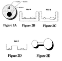
- adjacent wells of the microarray are connected by one or more channels which provide fluid communication between the adjacent wells ( Figures 1 and 2D-E).
- the connecting channels will have cross-section dimensions and length allowing control over the rate of transport of fluid, vapor, buffer, or precipitating or crystallizing agents through the channels.
- varying the dimensions of the channels controls protein crystal growth condition.
- protein crystal growth conditions are controlled by placing a material in the micro-channels that controls fluid communication between the wells. Non-limiting examples are membranes, acrylamide or agarose.
- the connecting micro-channels are from about 0.0001 to about 0.2 microns wide and from about 0.00005 to about 0.1 microns deep.
- the micro-channels are from about 0.0001 to about 2.0 microns wide and from about 0.00005 to about 0.5 microns deep.
- the micro-channels are formed in the microarray chip by the known etching techniques.
- FIG. 1 An example of two wells in a microarray (10) connected by a micro-channel is shown in Figure 1.
- the protein solution well 12 is connected to precipitate solution well 14 by a microchannel 16.
- the dimensions of each well are designed to hold the desired amount of solution and may have the same or different dimensions.
- protein sample is dispensed into well 12 to an initial liquid height 18 and precipitate solution is dispensed into well 14 with liquid height 20.
- the top of the wells and microchannel are sealed by an optically clear cover 22.
- the precipitate solution in well 14 has a lower vapor pressure than the protein solution in well 12, causing diffusion of solvent from well 12 to well 14 until the solution liquid height in well 12 reaches a final height 24.
- the concentration of the protein solution in well 12 precipitates protein crystal formation.
- the microarray can also include a known means for transmitting a fluid or gas to the wells of the microarray from an external source.
- an external mechanical pumping system marketed by Watson-Marlowe, Inc., under the trade designation "205U" can be used.
- the pumping system is a multi-channel cassette which delivers fluid or gas in reproducible and accurately controlled amounts.
- micro-valves are disposed in the wells and micro-channels to regulate the flow of fluid or vapor between the wells and through the micro-channels in a known manner.
- An automated dispensing mechanism capable of accurately and/or repeatedly dispensing picoliter and/or nanoliter volumes is also provided.
- the automated dispensing mechanism has an accuracy of at least about 90%.
- the automated dispensing mechanisms are preferably Piezo-based or fast solenoid dispensing mechanisms. More preferable, the dispensing mechanism is a fast solenoid dispensing mechanism.
- the dispenser has a large number of parallel capillaries. The capillaries are in fluid communication with a source of protein solution, a source of precipitate solution, and a source of buffer solution.
- the dispensing can be actuated by ultrasonic transducers that efficiently produce a pressure wave in the capillaries that contain the solutions.
- the dispenser is analogous to ink jet printer heads for computer printers but the fluid is not heated, thus not damaging the solutions.
- the protein solution preferably comprises an aqueous protein solution at a concentration of from about 0.1 ⁇ g/ ⁇ l to about 50 ⁇ g/ ⁇ l.
- the concentration is from about 0.1 ⁇ g/ ⁇ l to about 10 ⁇ g/ ⁇ l, more preferably from about 0.1 ⁇ g/ ⁇ l to about 1.0 ⁇ g/ ⁇ l.
- the protein solution comprises a detergent mixture when crystallizing membrane proteins.
- the precipitate solution preferably comprises a concentrated aqueous salt solution or polyethylene glycol as precipitating agents.
- the buffer solution preferably has pH between about 2 and about 10.
- the automated dispensing mechanism dispenses an initial volume of protein solution, an initial volume of precipitate solution, and an initial volume of buffer solution from the source of protein solution, the source of precipitate solution, and the source of buffer solution, respectively, into preselected wells or connecting channels of the microarray.
- the placement of the initial volume of protein solution, the initial volume of precipitate solution, and the initial volume of buffer solution in the preselected wells or channels of the microarray is dependent upon the method utilized to effect crystallization of the protein in the protein solution.
- Preferred methods to effect crystallization of the protein in the protein solution include liquid-liquid diffusion, batch diffusion, and vapor diffusion.
- the initial volume of protein solution is placed in one set of preselected wells, and the initial volume of precipitate solution is placed in a separate or different set of wells.
- the protein solution wells are connected to the precipitate solution wells by micro-channels.
- the initial volume of buffer solution may be placed in the micro-channels, or alternatively added directly to the initial volume of protein solution and/or precipitate solution.
- the concentration, amounts, precipitate type, and pH of the initial volumes of protein solution, precipitate solution, and buffer solution are primary conditions which determine protein crystal growth in a protein solution. In preparing the initial solutions, and in the automated dispensing mechanism placement, these conditions and the sample placement are varied in accordance with a pre-designed program.
- a cover plate is affixed to the microarray to convert the wells to micro-chambers and to convert the micro-channels to a capillary tube structure.
- the cover plate can made of the same or different material as the microarray, but the cover plate (or some portion of the well or chamber) must be transparent to permit optical analysis of the protein solutions in the chambers of the microarray.
- the cover plate will be glass or other material that is visually or optically clear, such as an optically clear tape.
- the environment surrounding the microarray can be controlled to limit evaporation of the solutions. Under controlled conditions of, for example, temperature and humidity, covering the samples may not be necessary.
- the crystallizing agent in the precipitate solution diffuses via the connecting capillaries to selected micro-chambers containing protein solution.
- Protein crystal growth in the different chambers are then monitored by high resolution or other optical means which automatically detects crystal growth based on well known edge analysis.
- the protein crystal growth can be monitored by manual inspection using high resolution microscopy or electron microscopy.
- the protein crystal growth in the chambers is monitored by high resolution optical means which automatically detects crystal growth based on edge analysis.
- that chamber's protein crystal growth conditions can be reproduced on a macro scale to produce a protein crystal which can be analyzed by x-ray crystallography. Alternatively, if a precipitate or clear sample is observed, the conditions in those samples can be used to optimize conditions for additional screening.
- the initial volume of protein solution is placed in one set of preselected wells, and the initial volume of precipitate solution is placed in a separate or different set of wells based on a pre-designed program, as with the liquid-liquid diffusion method (Figures 2D-E).
- the protein solution wells are connected to the precipitate solution wells by micro-channels.
- the initial volume of buffer solution is added to the initial volume of protein solution and/or initial volume of precipitate solution.
- the protein solution and precipitate solution can be placed in the same well such that the two solutions do not come into contact ( Figures 2A-C).
- the crystal growth is varied in different wells in accordance with a pre-designed program in which the placement, concentration, amounts, precipitate type, and pH conditions are varied in the different wells.
- a cover plate is then affixed to the microarray as with the liquid-liquid diffusion method.
- the vapor pressure of the precipitate solution is lower than the vapor pressure of the protein solution. This causes the protein solution in a micro-chamber which is connected via a capillary to a micro-chamber containing a precipitate solution to evaporate and become supersaturated causing precipitation of protein. Crystal growth is monitored as in the liquid-liquid diffusion.
- the protein solution is placed into wells of the microarray and the microarray is exposed to a single reservoir with the precipitate solution. This method allows for less fluid dispensing, but also less control of the protein crystal growth conditions with respect to each protein sample.
- the volume of protein solution, the volume of precipitate solution, and the volume of buffer solution are placed together in individual wells of the microarray.
- the chip does not have connecting channels between the wells.
- the crystal growth is varied in different wells in accordance with a pre-designed program in which the placement, concentration, amounts, precipitate type, and pH conditions are varied in the different wells.
- a cover plate is affixed to the microarray, and the crystal growth is then monitored.
- fluid or gas can delivered to the micro-chambers in reproducible and accurately controlled amounts from an external source by the external mechanical pumping system described above. Gas can also be delivered from the pressure generated by a standard glass bottle or tank. The fluid or gas delivered to the micro-chambers can be regulated by the micro-valves. The fluid or gas can be used to further alter the crystal growth conditions of the micro-chamber and increase the size of the protein crystals grown. These protein crystals can then be harvested and examined by x-ray crystallography or nuclear magnetic spectroscopy or other appropriate techniques.
- the present invention provides a method of screening protein crystal growth conditions on a nano or meso scale.
- the method provides a means of screening protein crystal growth conditions for proteins that cannot be expressed in milligram quantities as well as those that can be expressed in larger quantities.
- the substantial reduction in protein needed for the present invention reduces the costs associated with screening protein crystal growth conditions.
- the apparatus comprises a microarray for the protein and precipitate solutions, an automatic dispensing mechanism for dispensing the solutions and an automated means for analyzing crystal growth.
- the desired solutions i.e., protein, precipitate and a buffer
- the automatic dispensing mechanism dispenses discrete drops.
- Screening conditions such as the type of buffer and pH can be varied from sample to sample by programming the automatic dispenser. For example, arbitrary screens varying pH could be programmed by mixing the proper ratios using different drop counts from different stock solutions having different pH values. A pH range from 2.0 to 10.0 is then screened in steps of 0.2-0.5 pH units. Other conditions, such as crystallization agents and salt concentration are also controlled in a similar manner.
- Mixing of the reagents can either be done before dispensing or after the solutions are dispensed into the microarray.
- Mixing in the microarray can be accomplished by ultrasonic mixing, high-speed dispensing of picoliter drops, rapid temperature fluctuation, or by static diffusion.
- the wells of the microarray are sealed to control the microenvironment in the wells and to prevent evaporation of the solutions to dryness. More preferably, the wells are sealed with optically clear tape.
- Sealing the microarray involves an arm mounted on a YZ transverse mechanism. The X direction is along the plate transport direction. The arm, holding a roll of clear tape, moves past the last well in the row, drops to form positive vertical (Z axis) pressure, and then begins to move back in the negative Y direction while at the same time rotating the tape roll. Once the tape leaves the plate area, a guillotine mechanism shears the tape. The plate then moves in the X direction onto the next indexed row and the dispense process initializes again. Automated taping is reliably performed in many industries.
- Protein crystal growth in the different wells is monitored by high resolution optical means which automatically detects crystal growth based on well known edge analysis.
- image acquisitions systems are commercially available.
- Nanoliter protein droplets were used for vapor diffusion, batch and liquid diffusion crystallization screening.
- the protein solutions of either lysozyme, thaumatin, or NAD synthetase were applied using a five microliter Hamilton syringe.
- the tip of the Hamilton syringe was placed in contact with the wall of each experiment chamber.
- a variety of microarrays were designed to accommodate protein solution droplets with volume ranges of 5-20 nanoliters and precipitate volumes of 100-200 nanoliters.
- the array prototyping was accomplished using MicroScope slides with permanent sealing of neoprene gaskets of varying thickness (0.1 mm 0.5 mm).
- Crystals were observed in seventy percent of the droplets. While not wishing to be bound by theory, it is believed that the failure to observe crystals in 30% of the wells was due to inaccurate dispensing of the protein and precipitant five nanoliter drops in that the peizo tip did not position the drops together.
Landscapes
- Chemical & Material Sciences (AREA)
- Organic Chemistry (AREA)
- Engineering & Computer Science (AREA)
- Crystallography & Structural Chemistry (AREA)
- Materials Engineering (AREA)
- Metallurgy (AREA)
- Chemical Kinetics & Catalysis (AREA)
- General Chemical & Material Sciences (AREA)
- Crystals, And After-Treatments Of Crystals (AREA)
- Peptides Or Proteins (AREA)
Applications Claiming Priority (2)
| Application Number | Priority Date | Filing Date | Title |
|---|---|---|---|
| US12801899P | 1999-04-06 | 1999-04-06 | |
| EP00921690A EP1181548B1 (de) | 1999-04-06 | 2000-04-05 | Vorrichtung zum screening von kristallisierungsbedingungen in lösungen zur kristallzüchtung |
Related Parent Applications (1)
| Application Number | Title | Priority Date | Filing Date |
|---|---|---|---|
| EP00921690A Division EP1181548B1 (de) | 1999-04-06 | 2000-04-05 | Vorrichtung zum screening von kristallisierungsbedingungen in lösungen zur kristallzüchtung |
Publications (2)
| Publication Number | Publication Date |
|---|---|
| EP1701159A2 true EP1701159A2 (de) | 2006-09-13 |
| EP1701159A3 EP1701159A3 (de) | 2007-07-25 |
Family
ID=36658777
Family Applications (1)
| Application Number | Title | Priority Date | Filing Date |
|---|---|---|---|
| EP06075121A Withdrawn EP1701159A3 (de) | 1999-04-06 | 2000-04-05 | Verfahren zum Screening von Kristallisationsbedingungen für das Kristallwachstum von Proteinen in Lösung |
Country Status (1)
| Country | Link |
|---|---|
| EP (1) | EP1701159A3 (de) |
Cited By (1)
| Publication number | Priority date | Publication date | Assignee | Title |
|---|---|---|---|---|
| CN116745472A (zh) * | 2020-09-08 | 2023-09-12 | 克里斯托斯福斯特有限公司 | 针对生物大分子晶体中的小分子的阵列、浸泡溶液和选择浸泡条件的方法 |
Family Cites Families (6)
| Publication number | Priority date | Publication date | Assignee | Title |
|---|---|---|---|---|
| US4833233A (en) * | 1987-08-20 | 1989-05-23 | The United States Of America As Represented By The Administrator Of The National Aeronautics And Space Administration | Human serum albumin crystals and method of preparation |
| US5096676A (en) * | 1989-01-27 | 1992-03-17 | Mcpherson Alexander | Crystal growing apparatus |
| US5130105A (en) * | 1990-10-23 | 1992-07-14 | The United States Of America As Represented By The Administrator Of The National Aeronautics And Space Administration | Protein crystal growth tray assembly |
| US5419278A (en) * | 1994-05-25 | 1995-05-30 | Carter; Daniel C. | Vapor equilibration tray for growing protein crystals |
| US5641681A (en) * | 1995-04-17 | 1997-06-24 | The United States Of America As Represented By The Administrator Of The National Aeronautics And Space Administration | Device and method for screening crystallization conditions in solution crystal growth |
| DE19631395A1 (de) * | 1996-08-02 | 1998-02-05 | Basf Ag | Verfahren zum Wirkstoff-Screening |
-
2000
- 2000-04-05 EP EP06075121A patent/EP1701159A3/de not_active Withdrawn
Cited By (1)
| Publication number | Priority date | Publication date | Assignee | Title |
|---|---|---|---|---|
| CN116745472A (zh) * | 2020-09-08 | 2023-09-12 | 克里斯托斯福斯特有限公司 | 针对生物大分子晶体中的小分子的阵列、浸泡溶液和选择浸泡条件的方法 |
Also Published As
| Publication number | Publication date |
|---|---|
| EP1701159A3 (de) | 2007-07-25 |
Similar Documents
| Publication | Publication Date | Title |
|---|---|---|
| EP1181548B1 (de) | Vorrichtung zum screening von kristallisierungsbedingungen in lösungen zur kristallzüchtung | |
| US7214540B2 (en) | Method for screening crystallization conditions in solution crystal growth | |
| US20030022383A1 (en) | Method for screening crystallization conditions in solution crystal growth | |
| US7247490B2 (en) | Method for screening crystallization conditions in solution crystal growth | |
| JP4741042B2 (ja) | マイクロウェル・アレイ内の物質のスクリーリングの方法 | |
| US6485690B1 (en) | Multiple fluid sample processor and system | |
| US7244396B2 (en) | Method for preparation of microarrays for screening of crystal growth conditions | |
| US7285422B1 (en) | Systems and methods for preparing and analyzing low volume analyte array elements | |
| EP1322413B1 (de) | Verfahren und vorrichtung zur behandlung von biomolekülmatrizen | |
| US6569385B1 (en) | Systems and methods for preparing and analyzing low volume analyte array elements | |
| US20170028376A9 (en) | Systems for Filling a Sample Array by Droplet Dragging | |
| US20070281359A1 (en) | Method for preparation of microarrays for screening of crystal growth conditions | |
| EP1701159A2 (de) | Verfahren zum Screening von Kristallisationsbedingungen für das Kristallwachstum von Proteinen in Lösung | |
| US20070026528A1 (en) | Method for screening crystallization conditions in solution crystal growth | |
| WO2003035208A1 (en) | Method for preparation of microarrays for screening of crystal growth conditions |
Legal Events
| Date | Code | Title | Description |
|---|---|---|---|
| PUAI | Public reference made under article 153(3) epc to a published international application that has entered the european phase |
Free format text: ORIGINAL CODE: 0009012 |
|
| 17P | Request for examination filed |
Effective date: 20060119 |
|
| AC | Divisional application: reference to earlier application |
Ref document number: 1181548 Country of ref document: EP Kind code of ref document: P |
|
| AK | Designated contracting states |
Kind code of ref document: A2 Designated state(s): AT BE CH CY DE DK ES FI FR GB GR IE IT LI LU MC NL PT SE |
|
| AX | Request for extension of the european patent |
Extension state: AL LT LV MK RO SI |
|
| RIN1 | Information on inventor provided before grant (corrected) |
Inventor name: BRAY, TERRY L. Inventor name: DELUCAS, LAWRENCE J. |
|
| PUAL | Search report despatched |
Free format text: ORIGINAL CODE: 0009013 |
|
| AK | Designated contracting states |
Kind code of ref document: A3 Designated state(s): AT BE CH CY DE DK ES FI FR GB GR IE IT LI LU MC NL PT SE |
|
| AX | Request for extension of the european patent |
Extension state: AL LT LV MK RO SI |
|
| AKX | Designation fees paid |
Designated state(s): AT BE CH CY DE DK ES FI FR GB GR IE IT LI LU MC NL PT SE |
|
| AXX | Extension fees paid |
Extension state: MK Payment date: 20060119 Extension state: LV Payment date: 20060119 Extension state: LT Payment date: 20060119 Extension state: AL Payment date: 20060119 |
|
| STAA | Information on the status of an ep patent application or granted ep patent |
Free format text: STATUS: THE APPLICATION IS DEEMED TO BE WITHDRAWN |
|
| 18D | Application deemed to be withdrawn |
Effective date: 20071031 |