EP1701332A2 - Dispositif d'affichage d'images rétro-éclaires avec réduction des papillotements et du flou - Google Patents
Dispositif d'affichage d'images rétro-éclaires avec réduction des papillotements et du flou Download PDFInfo
- Publication number
- EP1701332A2 EP1701332A2 EP06004741A EP06004741A EP1701332A2 EP 1701332 A2 EP1701332 A2 EP 1701332A2 EP 06004741 A EP06004741 A EP 06004741A EP 06004741 A EP06004741 A EP 06004741A EP 1701332 A2 EP1701332 A2 EP 1701332A2
- Authority
- EP
- European Patent Office
- Prior art keywords
- image
- pixels
- motion
- frame
- display
- Prior art date
- Legal status (The legal status is an assumption and is not a legal conclusion. Google has not performed a legal analysis and makes no representation as to the accuracy of the status listed.)
- Withdrawn
Links
- 230000002829 reductive effect Effects 0.000 title description 5
- 230000033001 locomotion Effects 0.000 claims abstract description 81
- 238000005286 illumination Methods 0.000 claims abstract description 26
- 238000000034 method Methods 0.000 claims description 42
- 239000004973 liquid crystal related substance Substances 0.000 claims description 35
- 238000001514 detection method Methods 0.000 abstract description 7
- 230000006870 function Effects 0.000 description 25
- 230000007704 transition Effects 0.000 description 18
- 230000003287 optical effect Effects 0.000 description 15
- 230000002123 temporal effect Effects 0.000 description 14
- 210000004027 cell Anatomy 0.000 description 13
- 230000000694 effects Effects 0.000 description 11
- 238000002834 transmittance Methods 0.000 description 10
- 230000008859 change Effects 0.000 description 4
- 238000010586 diagram Methods 0.000 description 4
- 210000005252 bulbus oculi Anatomy 0.000 description 3
- 230000004044 response Effects 0.000 description 3
- 210000001525 retina Anatomy 0.000 description 3
- XUIMIQQOPSSXEZ-UHFFFAOYSA-N Silicon Chemical compound [Si] XUIMIQQOPSSXEZ-UHFFFAOYSA-N 0.000 description 2
- 230000003044 adaptive effect Effects 0.000 description 2
- 230000002411 adverse Effects 0.000 description 2
- 230000005540 biological transmission Effects 0.000 description 2
- 239000013078 crystal Substances 0.000 description 2
- 230000005684 electric field Effects 0.000 description 2
- 210000001508 eye Anatomy 0.000 description 2
- 230000014509 gene expression Effects 0.000 description 2
- 239000000463 material Substances 0.000 description 2
- 229910052710 silicon Inorganic materials 0.000 description 2
- 239000010703 silicon Substances 0.000 description 2
- 238000000149 argon plasma sintering Methods 0.000 description 1
- 238000003491 array Methods 0.000 description 1
- 230000008033 biological extinction Effects 0.000 description 1
- 239000003990 capacitor Substances 0.000 description 1
- 210000002421 cell wall Anatomy 0.000 description 1
- 239000003086 colorant Substances 0.000 description 1
- 230000008094 contradictory effect Effects 0.000 description 1
- 230000003247 decreasing effect Effects 0.000 description 1
- 230000006866 deterioration Effects 0.000 description 1
- 230000010339 dilation Effects 0.000 description 1
- 238000005516 engineering process Methods 0.000 description 1
- 238000000605 extraction Methods 0.000 description 1
- 239000010408 film Substances 0.000 description 1
- 230000010354 integration Effects 0.000 description 1
- 239000007788 liquid Substances 0.000 description 1
- 230000000877 morphologic effect Effects 0.000 description 1
- 230000008447 perception Effects 0.000 description 1
- 230000008569 process Effects 0.000 description 1
- 230000009467 reduction Effects 0.000 description 1
- 230000002441 reversible effect Effects 0.000 description 1
- 238000005070 sampling Methods 0.000 description 1
- 239000010409 thin film Substances 0.000 description 1
Images


Classifications
-
- G—PHYSICS
- G09—EDUCATION; CRYPTOGRAPHY; DISPLAY; ADVERTISING; SEALS
- G09G—ARRANGEMENTS OR CIRCUITS FOR CONTROL OF INDICATING DEVICES USING STATIC MEANS TO PRESENT VARIABLE INFORMATION
- G09G3/00—Control arrangements or circuits, of interest only in connection with visual indicators other than cathode-ray tubes
- G09G3/20—Control arrangements or circuits, of interest only in connection with visual indicators other than cathode-ray tubes for presentation of an assembly of a number of characters, e.g. a page, by composing the assembly by combination of individual elements arranged in a matrix no fixed position being assigned to or needed to be assigned to the individual characters or partial characters
- G09G3/34—Control arrangements or circuits, of interest only in connection with visual indicators other than cathode-ray tubes for presentation of an assembly of a number of characters, e.g. a page, by composing the assembly by combination of individual elements arranged in a matrix no fixed position being assigned to or needed to be assigned to the individual characters or partial characters by control of light from an independent source
- G09G3/3406—Control of illumination source
- G09G3/342—Control of illumination source using several illumination sources separately controlled corresponding to different display panel areas, e.g. along one dimension such as lines
- G09G3/3426—Control of illumination source using several illumination sources separately controlled corresponding to different display panel areas, e.g. along one dimension such as lines the different display panel areas being distributed in two dimensions, e.g. matrix
-
- G—PHYSICS
- G09—EDUCATION; CRYPTOGRAPHY; DISPLAY; ADVERTISING; SEALS
- G09G—ARRANGEMENTS OR CIRCUITS FOR CONTROL OF INDICATING DEVICES USING STATIC MEANS TO PRESENT VARIABLE INFORMATION
- G09G3/00—Control arrangements or circuits, of interest only in connection with visual indicators other than cathode-ray tubes
- G09G3/20—Control arrangements or circuits, of interest only in connection with visual indicators other than cathode-ray tubes for presentation of an assembly of a number of characters, e.g. a page, by composing the assembly by combination of individual elements arranged in a matrix no fixed position being assigned to or needed to be assigned to the individual characters or partial characters
- G09G3/34—Control arrangements or circuits, of interest only in connection with visual indicators other than cathode-ray tubes for presentation of an assembly of a number of characters, e.g. a page, by composing the assembly by combination of individual elements arranged in a matrix no fixed position being assigned to or needed to be assigned to the individual characters or partial characters by control of light from an independent source
- G09G3/3406—Control of illumination source
- G09G3/342—Control of illumination source using several illumination sources separately controlled corresponding to different display panel areas, e.g. along one dimension such as lines
-
- G—PHYSICS
- G09—EDUCATION; CRYPTOGRAPHY; DISPLAY; ADVERTISING; SEALS
- G09G—ARRANGEMENTS OR CIRCUITS FOR CONTROL OF INDICATING DEVICES USING STATIC MEANS TO PRESENT VARIABLE INFORMATION
- G09G2310/00—Command of the display device
- G09G2310/02—Addressing, scanning or driving the display screen or processing steps related thereto
- G09G2310/0237—Switching ON and OFF the backlight within one frame
-
- G—PHYSICS
- G09—EDUCATION; CRYPTOGRAPHY; DISPLAY; ADVERTISING; SEALS
- G09G—ARRANGEMENTS OR CIRCUITS FOR CONTROL OF INDICATING DEVICES USING STATIC MEANS TO PRESENT VARIABLE INFORMATION
- G09G2310/00—Command of the display device
- G09G2310/02—Addressing, scanning or driving the display screen or processing steps related thereto
- G09G2310/024—Scrolling of light from the illumination source over the display in combination with the scanning of the display screen
-
- G—PHYSICS
- G09—EDUCATION; CRYPTOGRAPHY; DISPLAY; ADVERTISING; SEALS
- G09G—ARRANGEMENTS OR CIRCUITS FOR CONTROL OF INDICATING DEVICES USING STATIC MEANS TO PRESENT VARIABLE INFORMATION
- G09G2310/00—Command of the display device
- G09G2310/08—Details of timing specific for flat panels, other than clock recovery
-
- G—PHYSICS
- G09—EDUCATION; CRYPTOGRAPHY; DISPLAY; ADVERTISING; SEALS
- G09G—ARRANGEMENTS OR CIRCUITS FOR CONTROL OF INDICATING DEVICES USING STATIC MEANS TO PRESENT VARIABLE INFORMATION
- G09G2320/00—Control of display operating conditions
- G09G2320/02—Improving the quality of display appearance
- G09G2320/0252—Improving the response speed
-
- G—PHYSICS
- G09—EDUCATION; CRYPTOGRAPHY; DISPLAY; ADVERTISING; SEALS
- G09G—ARRANGEMENTS OR CIRCUITS FOR CONTROL OF INDICATING DEVICES USING STATIC MEANS TO PRESENT VARIABLE INFORMATION
- G09G2320/00—Control of display operating conditions
- G09G2320/02—Improving the quality of display appearance
- G09G2320/0257—Reduction of after-image effects
-
- G—PHYSICS
- G09—EDUCATION; CRYPTOGRAPHY; DISPLAY; ADVERTISING; SEALS
- G09G—ARRANGEMENTS OR CIRCUITS FOR CONTROL OF INDICATING DEVICES USING STATIC MEANS TO PRESENT VARIABLE INFORMATION
- G09G2320/00—Control of display operating conditions
- G09G2320/02—Improving the quality of display appearance
- G09G2320/0261—Improving the quality of display appearance in the context of movement of objects on the screen or movement of the observer relative to the screen
-
- G—PHYSICS
- G09—EDUCATION; CRYPTOGRAPHY; DISPLAY; ADVERTISING; SEALS
- G09G—ARRANGEMENTS OR CIRCUITS FOR CONTROL OF INDICATING DEVICES USING STATIC MEANS TO PRESENT VARIABLE INFORMATION
- G09G2320/00—Control of display operating conditions
- G09G2320/06—Adjustment of display parameters
- G09G2320/0626—Adjustment of display parameters for control of overall brightness
- G09G2320/0646—Modulation of illumination source brightness and image signal correlated to each other
-
- G—PHYSICS
- G09—EDUCATION; CRYPTOGRAPHY; DISPLAY; ADVERTISING; SEALS
- G09G—ARRANGEMENTS OR CIRCUITS FOR CONTROL OF INDICATING DEVICES USING STATIC MEANS TO PRESENT VARIABLE INFORMATION
- G09G2320/00—Control of display operating conditions
- G09G2320/06—Adjustment of display parameters
- G09G2320/0666—Adjustment of display parameters for control of colour parameters, e.g. colour temperature
-
- G—PHYSICS
- G09—EDUCATION; CRYPTOGRAPHY; DISPLAY; ADVERTISING; SEALS
- G09G—ARRANGEMENTS OR CIRCUITS FOR CONTROL OF INDICATING DEVICES USING STATIC MEANS TO PRESENT VARIABLE INFORMATION
- G09G2320/00—Control of display operating conditions
- G09G2320/10—Special adaptations of display systems for operation with variable images
- G09G2320/103—Detection of image changes, e.g. determination of an index representative of the image change
-
- G—PHYSICS
- G09—EDUCATION; CRYPTOGRAPHY; DISPLAY; ADVERTISING; SEALS
- G09G—ARRANGEMENTS OR CIRCUITS FOR CONTROL OF INDICATING DEVICES USING STATIC MEANS TO PRESENT VARIABLE INFORMATION
- G09G2340/00—Aspects of display data processing
- G09G2340/16—Determination of a pixel data signal depending on the signal applied in the previous frame
-
- G—PHYSICS
- G09—EDUCATION; CRYPTOGRAPHY; DISPLAY; ADVERTISING; SEALS
- G09G—ARRANGEMENTS OR CIRCUITS FOR CONTROL OF INDICATING DEVICES USING STATIC MEANS TO PRESENT VARIABLE INFORMATION
- G09G3/00—Control arrangements or circuits, of interest only in connection with visual indicators other than cathode-ray tubes
- G09G3/20—Control arrangements or circuits, of interest only in connection with visual indicators other than cathode-ray tubes for presentation of an assembly of a number of characters, e.g. a page, by composing the assembly by combination of individual elements arranged in a matrix no fixed position being assigned to or needed to be assigned to the individual characters or partial characters
- G09G3/34—Control arrangements or circuits, of interest only in connection with visual indicators other than cathode-ray tubes for presentation of an assembly of a number of characters, e.g. a page, by composing the assembly by combination of individual elements arranged in a matrix no fixed position being assigned to or needed to be assigned to the individual characters or partial characters by control of light from an independent source
- G09G3/36—Control arrangements or circuits, of interest only in connection with visual indicators other than cathode-ray tubes for presentation of an assembly of a number of characters, e.g. a page, by composing the assembly by combination of individual elements arranged in a matrix no fixed position being assigned to or needed to be assigned to the individual characters or partial characters by control of light from an independent source using liquid crystals
- G09G3/3611—Control of matrices with row and column drivers
- G09G3/3648—Control of matrices with row and column drivers using an active matrix
- G09G3/3666—Control of matrices with row and column drivers using an active matrix with the matrix divided into sections
Definitions
- the present invention relates to backlit displays and, more particularly, to a backlit display with improved performance characteristics.
- the local transmittance of a liquid crystal display (LCD) panel or a liquid crystal on silicon (LCOS) display can be varied to modulate the intensity of light passing from a backlit source through an area of the panel to produce a pixel that can be displayed at a variable intensity. Whether light from the source passes through the panel to a viewer or is blocked is determined by the orientations of molecules of liquid crystals in a light valve.
- LCD liquid crystal display
- LCOS liquid crystal on silicon
- LCD panels used for computer displays and video screens are typically backlit with fluorescent tubes or arrays of light-emitting diodes (LEDs) that are built into the sides or back of the panel.
- LEDs light-emitting diodes
- the transmittance of the light valve is controlled by a layer of liquid crystals interposed between a pair of polarizers.
- Light from the source impinging on the first polarizer comprises electromagnetic waves vibrating in a plurality of planes. Only that portion of the light vibrating in the plane of the optical axis of a polarizer can pass through the polarizer.
- the optical axes of the first and second polarizers are arranged at an angle so that light passing through the first polarizer would normally be blocked from passing through the second polarizer in the series.
- a layer of translucent liquid crystals occupies a cell gap separating the two polarizers.
- the physical orientation of the molecules of liquid polarizers are arranged at an angle so that light passing through the first polarizer would normally be blocked from passing through the second polarizer in the series.
- a layer of translucent liquid crystals occupies a cell gap separating the two polarizers.
- the physical orientation of the molecules of liquid crystal can be controlled and the plane of vibration of light transiting the columns of molecules spanning the layer can be rotated to either align or not align with the optical axes of the polarizers. It is to be understood that normally white may likewise be used.
- the surfaces of the first and second polarizers forming the walls of the cell gap are grooved so that the molecules of liquid crystal immediately adjacent to the cell gap walls will align with the grooves and, thereby, be aligned with the optical axis of the respective polarizer.
- Molecular forces cause adjacent liquid crystal molecules to attempt to align with their neighbors with the result that the orientation of the molecules in the column spanning the cell gap twist over the length of the column.
- the plane of vibration of light transiting the column of molecules will be "twisted" from the optical axis of the first polarizer to that of the second polarizer.
- liquid crystals With the liquid crystals in this orientation, light from the source can pass through the series polarizers of the translucent panel assembly to produce a lighted area of the display surface when viewed from the front of the panel. It is to be understood that the grooves may be omitted in some configurations.
- a voltage typically controlled by a thin film transistor, is applied to an electrode in an array of electrodes deposited on one wall of the cell gap.
- the liquid crystal molecules adjacent to the electrode are attracted by the field created by the voltage and rotate to align with the field.
- the column of crystals is "untwisted," and the optical axes of the crystals adjacent the cell wall are rotated out of alignment with the optical axis of the corresponding polarizer progressively reducing the local transmittance of the light valve and the intensity of the corresponding display pixel.
- Color LCD displays are created by varying the intensity of transmitted light for each of a plurality of primary color elements (typically, red, green, and blue) that make up a display pixel.
- LCDs can produce bright, high resolution, color images and are thinner, lighter, and draw less power than cathode ray tubes (CRTs).
- CRTs cathode ray tubes
- LCD usage is pervasive for the displays of portable computers, digital clocks and watches, appliances, audio and video equipment, and other electronic devices.
- the use of LCDs in certain "high end markets," such as video and graphic arts, is frustrated, in part, by the limited performance of the display.
- Baba et al. U.S. Patent Publication Number 2002/0003522 A1 describe a display for a liquid crystal display that includes a flashing period for the backlight of the display that is based upon the brightness level of the image.
- an estimation of the amount of motion of the video content is determined to change the flashing width of the backlight for the display.
- the light source of the backlight may be lighted with lower brightness in the non-lightening period than in the lightening period.
- higher brightness images requires less non-lightening period and thus tends to suffer from a blurring effect for video content with motion.
- To reduce the blurring of the image Baba et al. uses a motion estimation, which is computationally complex, to determine if an image has sufficient motion. For images with sufficient motion the non-lightening period is increased so that the image blur is reduced. Unfortunately, this tends to result in a dimmer image.
- a backlit display 20 comprises, generally, a backlight 22, a diffuser 24, and a light valve 26 (indicated by a bracket) that controls the transmittance of light from the backlight 22 to a user viewing an image displayed at the front of the panel 28.
- the light valve typically comprising a liquid crystal apparatus, is arranged to electronically control the transmittance of light for a picture element or pixel. Since liquid crystals do not emit light, an external source of light is necessary to create a visible image.
- the source of light for small and inexpensive LCDs, such as those used in digital clocks or calculators, may be light that is reflected from the back surface of the panel after passing through the panel.
- LCDs absorb a significant portion of the light passing through the assembly and an artificial source of light such as the backlight 22 comprising fluorescent light tubes or an array of light sources 30 (e.g., light-emitting diodes (LEDs)), as illustrated in FIGS. 1A and 1 B, are useful to produce pixels of sufficient intensity for highly visible images or to illuminate the display in poor lighting conditions.
- LEDs light-emitting diodes
- Light radiating from the light sources 30 of the backlight 22 comprises electromagnetic waves vibrating in random planes. Only those light waves vibrating in the plane of a polarizer's optical axis can pass through the polarizer.
- the light valve 26 includes a first polarizer 32 and a second polarizer 34 having optical axes arrayed at an angle so that normally light cannot pass through the series of polarizers. Images are displayable with an LCD because local regions of a liquid crystal layer 36 interposed between the first 32 and second 34 polarizer can be electrically controlled to alter the alignment of the plane of vibration of light relative of the optical axis of a polarizer and, thereby, modulate the transmittance of local regions of the panel corresponding to individual pixels 36 in an array of display pixels.
- the layer of liquid crystal molecules 36 occupies a cell gap having walls formed by surfaces of the first 32 and second 34 polarizers.
- the walls of the cell gap are rubbed to create microscopic grooves aligned with the optical axis of the corresponding polarizer.
- the grooves cause the layer of liquid crystal molecules adjacent to the walls of the cell gap to align with the optical axis of the associated polarizer.
- each succeeding molecule in the column of molecules spanning the cell gap will attempt to align with its neighbors.
- the result is a layer of liquid crystals comprising innumerable twisted columns of liquid crystal molecules that bridge the cell gap.
- a voltage is applied to a spatially corresponding electrode of a rectangular array of transparent electrodes deposited on a wall of the cell gap.
- the resulting electric field causes molecules of the liquid crystal adjacent to the electrode to rotate toward alignment with the field.
- the effect is to "untwist" the column of molecules so that the plane of vibration of the light is progressively rotated away from the optical axis of the polarizer as the field strength increases and the local transmittance of the light valve 26 is reduced.
- the pixel 28 progressively darkens until the maximum extinction of light 40 from the light source 42 is obtained.
- Color LCD displays are created by varying the intensity of transmitted light for each of a plurality of primary color elements (typically, red, green, and blue) elements making up a display pixel. Other arrangements of structures may likewise be used.
- the LCD uses transistors as a select switch for each pixel, and adopts a display method (hereinafter, called as a "hold-type display”), in which a displayed image is held for a frame period.
- a CRT hereinafter, called as an "impulse-type display”
- the black is displayed between each frame of the motion image rewritten in 60 Hz in case of the impulse-type display like the CRT. That is, the black is displayed excluding a period when the image is displayed, and one frame of the motion image is presented respectively to the viewer as an independent image. Therefore, the image is observed as a clear motion image in the impulse-type display.
- the LCD is fundamentally different from CRT in time axis hold characteristic in an image display. Therefore, when the motion image is displayed on a LCD, image deterioration such as blurring the image is caused.
- image deterioration arises from a viewer that follows the moving object of the motion image (when the eyeball movement of the viewer is a following motion), even if the image is rewritten, for example, at 60 Hz discrete steps.
- the eyeball has a characteristic to attempt to smoothly follow the moving object even though it is discretely presented in a "hold type" manner.
- the displayed image of one frame of the motion image is held for one frame period, and is presented to the viewer during the corresponding period as a still image. Therefore, even though the eyeball of the viewer smoothly follows the moving object, the displayed image stands still for one frame period. Therefore, the shifted image is presented according to the speed of the moving object on the retina of the viewer. Accordingly, the image will appear blurred to the viewer due to integration by the eye. In addition, since the change between the images presented on the retina of the viewer increases with greater speed, such images become even more blurred.
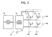
- the backlight 22 comprises an array of locally controllable light sources 30.
- the individual light sources 30 of the backlight may be light-emitting diodes (LEDs), an arrangement of phosphors and lensets, or other suitable light-emitting devices.
- the backlight may include a set of independently controllable light sources, such one or more cold cathode ray tubes.
- the light-emitting diodes may be 'white' and/or separate colored light emitting diodes.
- the individual light sources 30 of the backlight array 22 are independently controllable to output light at a luminance level independent of the luminance level of light output by the other light sources so that a light source can be modulated in response to any suitable signal.
- the light sources 30 (LEDs illustrated) of the array 22 are typically arranged in the rows, for examples, rows 50a and 50b, (indicated by brackets) and columns, for examples, columns 52a and 52b (indicated by brackets) of a rectangular array.
- the output of the light sources 30 of the backlight are controlled by a backlight driver 53.
- the light sources 30 are driven by a light source driver 54 that powers the elements by selecting a column of elements 52a or 52b by actuating a column selection transistor 55 and connecting a selected light source 30 of the selected column to ground 56.
- a data processing unit 58 processing the digital values for pixels of an image to be displayed, provides a signal to the light driver 54 to select the appropriate light source 30 corresponding to the displayed pixel and to drive the light source with a power level to produce an appropriate level of illumination of the light source.
- FIG. 3 illustrates a block diagram of a typical data path within a liquid crystal panel.
- the video data 100 may be provided from any suitable source, such as for example, television broadcast, Internet connection, file server, digital video disc, computer, video on demand, or broadcast.
- the video data 100 is provided to a scanning and timing generator 102 where the video data is converted to a suitable format for presentation on the display.
- each line of data is provided to an overdrive circuit 104, in combination with a frame buffer 106, to compensate for the slow temporal response of the display.
- the signal from the overdrive 104 is preferably converted to a voltage value in the data driver 108 which is output to individual data electrodes of the display.
- the generator 102 also provides a clock signal to the gate driver 110, thereby selecting one row at a time, which stores the voltage data on the data electrode on the storage capacitor of each pixel of the display.
- the generator 102 also provides backlight control signals 112 to control the level of luminance from the backlight, and/or the color or color balance of the light provided in the case of spatially non-uniform backlight (e.g., based upon image content and/or spatially different in different regions of the display).
- FIG. 4 illustrates the effect of flashing the backlight during only a portion of the frame. It is preferable that the flashing of the backlight is toward the end of the frame where the transmission of the liquid crystal material has reached or otherwise is approaching the target level. For example, the majority of the duration of the flashing backlight is preferably during the last third of the frame period.
- the backlight While modulating the backlight in some manner reduces the perceived motion blur, it unfortunately tends to result in a flickering artifact, due to the general 'impulse' nature of the resulting display technique. In order to reduce the flickering, the backlight may be flashed at a higher rate.
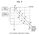
- FIG. 5 a graph of the motion of a portion of an image across a display over time is illustrated.
- the image would appear to the user at each time interval (e.g., frame rate).
- the image would appear at position 200 at the end of the first frame, is shifted and would appear at position 210 at the end of the second frame, is shifted and would appear at position 220 at the end of the third frame, and is shifted and would appear at position 230 at the end of the fourth frame.
- the moving image would be 'flashed' to the viewer at four different times corresponding to four different positions.
- a second flash When a second flash is included at the frame rate it may be centrally timed during the frame, and is illustrated by the dashed line 235.
- the image would appear to the user at each time interval central to the frame. In particular the image would appear at position 240 at the middle of the first frame, is shifted and would appear at position 250 at the middle of the second frame, is shifted and would appear at position 260 at the middle of the third frame, and is shifted and would appear at position 270 at the middle of the fourth frame. Accordingly, the moving image would be 'flashed' to the viewer at four additional different times corresponding to four different positions.
- the ghosting of the image results in relatively poor image quality with respect to motion.
- One technique to reduce the effect of blurring is to drive the liquid crystal display at the same rate as the backlight together with motion compensated frame interpolation. While a plausible solution, there is significant increased cost associated with the motion estimate and increased frame rate.
- the image may be divided into a set of regions, such as for example blocks.
- the blocks may include a single or group of light emitting diodes, or one or more cold cathode fluorescent tubes.
- the corresponding regions of the light valve may include one or a group of pixels.
- the backlight for each region is operated in a manner that is independent of other regions, or otherwise each of the regions may have a different luminance value or color (e.g., color temperature or set of colors).
- the luminance of the backlight in different regions is changed, such as from "on” to "off", or some level there between.
- a motion detection scheme may be used for each region to determine those in which sufficient motion exists, which are likely to exhibit blurring.
- the remaining regions may be classified as where insufficient motion exists, which are not likely to exhibit blurring. This is the same as the regions where insufficient motion exists may be determined and the remaining regions classified as where sufficient motion exists. In some manner, some regions likely to exhibit blurring and some regions not likely to exhibit blurring are identified.
- the regions identified as including sufficient motion may be illuminated with a backlight technique in a first manner that preferably tends to reduce the blurring without significant regard for flickering.
- the regions identified as including insufficient motion are illuminated with a backlight technique that preferably tends to reduce the amount of flickering without significant regard for blurring.
- the floor(t) may be a set level, may be based upon the content of the image, or otherwise may be adaptive.
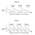
- the desired backlight level is compared to the first screen function, and if the desired backlight level is greater than the screen function, the backlight is on as indicated with the thick solid lines. In this manner, the motion blur may be selected in relation to the desired backlight level.
- Other suitable techniques may likewise be used.
- the desired backlight level is compared to the screen function, and if the desired backlight level is greater than the screen function, the backlight is on as indicated with the thick solid lines.
- the backlight in FIG. 7 has a greater frequency than the backlight in FIG. 6, such as twice the frequency, and thus tends to reduce the perception of flickering.
- Other suitable techniques may likewise be used.
- the area for the illuminated region of FIG. 6 and the illuminated region of FIG. 7 are substantially the same, within 10%, 25%, or 50%.
- the first two frames have a backlight flashing at a rate of twice the frame rate, and then the following three frames have a backlight flashing at a rate equal to the frame rate.
- the time 260 between backlight flashing increases. This transition 260 between different backlight flashing rates when combined with motion tends to result in an effect similar to flickering.
- the system should include a transition to smooth out the average temporal spacing between backlight flashing.
- the transition from cluster (first screen function) to disperse (second screen function) is the reverse of the transition from disperse (second screen function) to cluster (first screen function). As it may be observed, the effect is to reduce the abruptness of the transition between the disperse and cluster blacklight flashing techniques.
- the frame may be subdivided into a temporal frame time including multiple subfields.
- the intensity ("on" width) of the backlight can be approximated with number of "on” subfields. The more "on” subfields, the higher the backlight output.
- disperse screen is designated to be the first function
- cluster screen to be the second function
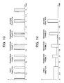
- transition frames 1, 2 and 3 are used between the first function and the second function, as illustrated in FIG. 13.
- FIG. 14 illustrates another embodiment where the first function is a continuous 'on" during the whole frame (or a majority of the frame) at one level, and the second function is a higher intensity level with shorter duration near the end of the frame.
- the transition frames are used to reduce the flickering effect due to transition from motion to non-motion, or from non-motion to motion.
- the intensity of the backlight is set such that the area in any frame is generally equal to the desired backlight level.
- FIG. 10 illustrates an exemplary flow diagram to convert high dynamic range video to be displayed on a high dynamic range display, consisting of a low resolution backlight and higher resolution LCD.
- Each HDR image 300 is low-pass filtered 302 and then sub-sampled to the backlight resolution.
- the vertical position 304 may be extracted and crosstalk correction 306 performed.
- the backlight resolution is determined by the number of backlight units, e.g. the number of LEDs in the backlight.
- Each pixel in the low resolution backlight image corresponds to a block in the HDR image.
- each backlight block motion detection 308 is performed to determine whether it is a motion block or still block.
- each backlight block may be subdivided into sub-blocks.
- each sub-block consists of 8x8 pixels in the high resolution HDR image.
- the process of motion detection may be as follows:
- the screen generation 310 is based upon the motion detection 308 and the vertical position extraction 304.
- a screen function 312 may be selected based upon the corrected image 306 and the screen generation 310.
- the backlight driver 314 receives the output of the screen function 312 to determine which backlight to illuminate and the level of illumination of the backlight(s).
- the screen generation 310 may provide an input to a LCD overdrive 316 which in combination with a backlight prediction 318 and an up-sampling 320 provides overdrive data to the HDR image 300.
- the technique described with reference to FIG. 10 includes the determination of motion for a region of the display. Since the light from the display tends to scatter somewhat, it is desirable to define the motion region larger than the region identified as including sufficient motion. In this manner, this additional region likely to exhibit light scattering will be provided with a suitable screen function so as to reduce the effects of blurring.
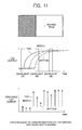
- FIG. 11 shows a moving edge and the LCD temporal response at three locations: top, middle, and bottom.
- the top row has a longest time for LCD to reach target level, while the bottom row has a shortest time, which is not enough to drive the LCD to the target level.
- a vertical edge can be seen to have different brightness from top to bottom. This brightness variation couples with the discrete backlight flashing causes ghost edges as shown in FIG. 11 (right).
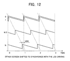
- the screen as shown in FIG. 7 is shifted in time to compensate the LCD driving timing difference.
- the vertical position of each backlight pixel is extracted and it is combined with the motion detection output to generate a screen (see FIG. 9).
- FIG. 12 shows the timing of cluster screen as a function of vertical position. The screen is shifted according to the LCD driving. For still image block using disperse screen, shifting is not needed, because it won't result in substantial artifacts.
- the backlight value can be derived from the down-sampled backlight image.
- One way is to take square root of the backlight image. Since the light from a backlight unit (LED) can spread to its neighboring blocks, crosstalk correction is used to compensate this spread.
- the corrected backlight value is compared to the screen as shown in FIGS. 6 and 7 to temporally modulate the backlight to achieve the desired output.
- the actual backlight image that illuminates the LCD can be predicted by convolving the backlight signal with the point spread function (PSF) of the backlight and it is up-sampled to the same resolution as the HDR image.
- gamma correction may be performed to convert LCD transmittance (T LCD ) into LCD driving digital counts.
- an adaptive recursive overdrive that can compensate for the timing of backlight.
- the AROD may be a modified recursive overdrive (ROD) algorithm that adapts to the screen.
- the backlight may be set to a uniform level, and the LED image is the same as the input image. If the temporal screen indicates that it is a still block (non-motion thus using dispersed screen), there is no need for overdrive. For the motion blocks, a cluster screen is used and overdrive is used as shown in FIG. 11.
- the current digital count (x n ) and the predicted LCD output level in the frame buffer are input to the overdrive circuit, where a new drive value (z n ) is derived based on a set of overdrive lookup tables.
- the new drive value is sent to the display prediction circuit and stored in the frame buffer for use in the next frame.
- Dynamic gamma is derived using the timing and width of the backlight and overdrive table is derived from the dynamic gamma data.
Landscapes
- Engineering & Computer Science (AREA)
- Physics & Mathematics (AREA)
- Computer Hardware Design (AREA)
- General Physics & Mathematics (AREA)
- Theoretical Computer Science (AREA)
- Control Of Indicators Other Than Cathode Ray Tubes (AREA)
- Liquid Crystal Display Device Control (AREA)
- Liquid Crystal (AREA)
- Transforming Electric Information Into Light Information (AREA)
Applications Claiming Priority (3)
| Application Number | Priority Date | Filing Date | Title |
|---|---|---|---|
| US66000805P | 2005-03-09 | 2005-03-09 | |
| US68523805P | 2005-05-26 | 2005-05-26 | |
| US11/157,231 US8115728B2 (en) | 2005-03-09 | 2005-06-20 | Image display device with reduced flickering and blur |
Publications (2)
| Publication Number | Publication Date |
|---|---|
| EP1701332A2 true EP1701332A2 (fr) | 2006-09-13 |
| EP1701332A3 EP1701332A3 (fr) | 2009-02-25 |
Family
ID=36602573
Family Applications (1)
| Application Number | Title | Priority Date | Filing Date |
|---|---|---|---|
| EP06004741A Withdrawn EP1701332A3 (fr) | 2005-03-09 | 2006-03-08 | Dispositif d'affichage d'images rétro-éclaires avec réduction des papillotements et du flou |
Country Status (3)
| Country | Link |
|---|---|
| US (1) | US8115728B2 (fr) |
| EP (1) | EP1701332A3 (fr) |
| JP (1) | JP2006251796A (fr) |
Cited By (5)
| Publication number | Priority date | Publication date | Assignee | Title |
|---|---|---|---|---|
| WO2010103424A1 (fr) * | 2009-03-09 | 2010-09-16 | Koninklijke Philips Electronics N.V. | Appareil anti-flou pour, par exemple, le rétroéclairage d'un dispositif d'affichage à cristaux liquides |
| EP2279506A4 (fr) * | 2008-05-29 | 2011-07-13 | Sharp Kk | Procédés et systèmes de réduction de scintillement et de flou |
| EP2434474A4 (fr) * | 2009-05-19 | 2013-03-27 | Sharp Kk | Dispositif d'affichage à cristaux liquides et procédé de commande |
| US8624938B2 (en) | 2008-12-19 | 2014-01-07 | Semiconductor Energy Laboratory Co., Ltd. | Method for driving liquid crystal display device |
| EP2394263A4 (fr) * | 2009-02-06 | 2014-12-10 | Semiconductor Energy Lab | Procédé de pilotage de dispositif d'affichage |
Families Citing this family (50)
| Publication number | Priority date | Publication date | Assignee | Title |
|---|---|---|---|---|
| JP4904783B2 (ja) * | 2005-03-24 | 2012-03-28 | ソニー株式会社 | 表示装置及び表示方法 |
| TWI301603B (en) * | 2005-09-02 | 2008-10-01 | Au Optronics Corp | Driving system and method for liquid crystal display |
| JP2007086298A (ja) * | 2005-09-21 | 2007-04-05 | Seiko Epson Corp | 画像表示装置、プロジェクションシステム、情報処理装置、画像表示装置の駆動方法、画像表示装置の駆動プログラム、記録媒体 |
| TWI361411B (en) * | 2006-11-03 | 2012-04-01 | Chimei Innolux Corp | Motion detection apparatus and method applied to liquid crystal display device |
| JP2008287119A (ja) * | 2007-05-18 | 2008-11-27 | Semiconductor Energy Lab Co Ltd | 液晶表示装置の駆動方法 |
| US20090085488A1 (en) * | 2007-10-01 | 2009-04-02 | Garmin Ltd. | Backlight for electronic devices |
| EP2208354A4 (fr) | 2007-10-10 | 2010-12-22 | Gerard Dirk Smits | Projecteur d'image avec suivi de lumière réfléchie |
| US20090122087A1 (en) * | 2007-11-02 | 2009-05-14 | Junichi Maruyama | Display device |
| JP2009139930A (ja) * | 2007-11-13 | 2009-06-25 | Mitsumi Electric Co Ltd | バックライト装置及びこれを用いた液晶表示装置 |
| KR101512050B1 (ko) * | 2008-01-25 | 2015-04-16 | 삼성디스플레이 주식회사 | 광원 로컬 디밍 방법, 이를 수행하기 위한 백라이트어셈블리 및 이를 갖는 표시장치 |
| US7551341B1 (en) * | 2008-01-28 | 2009-06-23 | Dolby Laboratories Licensing Corporation | Serial modulation display having binary light modulation stage |
| JP5211732B2 (ja) * | 2008-02-14 | 2013-06-12 | ソニー株式会社 | 点灯期間設定方法、表示パネルの駆動方法、点灯条件設定装置、半導体デバイス、表示パネル及び電子機器 |
| KR20090102083A (ko) * | 2008-03-25 | 2009-09-30 | 삼성전자주식회사 | 디스플레이 장치 및 디스플레이 방법 |
| US8610654B2 (en) * | 2008-07-18 | 2013-12-17 | Sharp Laboratories Of America, Inc. | Correction of visible mura distortions in displays using filtered mura reduction and backlight control |
| US20100013750A1 (en) * | 2008-07-18 | 2010-01-21 | Sharp Laboratories Of America, Inc. | Correction of visible mura distortions in displays using filtered mura reduction and backlight control |
| US8531380B2 (en) * | 2008-07-22 | 2013-09-10 | Sharp Laboratories Of America, Inc. | Methods and systems for area adaptive backlight management |
| US8890902B2 (en) * | 2008-10-14 | 2014-11-18 | Dolby Laboratories Licensing Corporation | Backlight simulation at reduced resolutions to determine spatial modulation of light for high dynamic range images |
| US8405770B2 (en) * | 2009-03-12 | 2013-03-26 | Intellectual Ventures Fund 83 Llc | Display of video with motion |
| JP5448981B2 (ja) | 2009-04-08 | 2014-03-19 | 株式会社半導体エネルギー研究所 | 液晶表示装置の駆動方法 |
| KR20100132855A (ko) * | 2009-06-10 | 2010-12-20 | 삼성에스디아이 주식회사 | 발광 장치 및 그 구동 방법 |
| US9692946B2 (en) * | 2009-06-29 | 2017-06-27 | Dolby Laboratories Licensing Corporation | System and method for backlight and LCD adjustment |
| EP2284827A1 (fr) * | 2009-07-15 | 2011-02-16 | Trident Microsystems (Far East) Ltd. | Unité de rétroéclairage et son procédé de commande |
| US8581941B2 (en) * | 2009-10-02 | 2013-11-12 | Panasonic Corporation | Backlight device and display apparatus |
| US10178406B2 (en) | 2009-11-06 | 2019-01-08 | Qualcomm Incorporated | Control of video encoding based on one or more video capture parameters |
| US8837576B2 (en) * | 2009-11-06 | 2014-09-16 | Qualcomm Incorporated | Camera parameter-assisted video encoding |
| US20110292997A1 (en) * | 2009-11-06 | 2011-12-01 | Qualcomm Incorporated | Control of video encoding based on image capture parameters |
| US12025807B2 (en) | 2010-10-04 | 2024-07-02 | Gerard Dirk Smits | System and method for 3-D projection and enhancements for interactivity |
| EP2625845B1 (fr) | 2010-10-04 | 2021-03-03 | Gerard Dirk Smits | Système et procédé de projection en 3d et améliorations d'interactivité |
| CN103380450B (zh) | 2011-02-15 | 2016-07-06 | 三菱电机株式会社 | 图像处理装置、图像显示装置以及图像处理方法 |
| JP5782787B2 (ja) * | 2011-04-01 | 2015-09-24 | ソニー株式会社 | 表示装置および表示方法 |
| JP5868048B2 (ja) * | 2011-07-19 | 2016-02-24 | キヤノン株式会社 | 制御装置及びその制御方法 |
| US9265458B2 (en) | 2012-12-04 | 2016-02-23 | Sync-Think, Inc. | Application of smooth pursuit cognitive testing paradigms to clinical drug development |
| US9380976B2 (en) | 2013-03-11 | 2016-07-05 | Sync-Think, Inc. | Optical neuroinformatics |
| KR20150066888A (ko) * | 2013-12-09 | 2015-06-17 | 삼성전자주식회사 | 디스플레이 장치 및 그 제어방법 |
| JP5945559B2 (ja) * | 2014-02-26 | 2016-07-05 | ドルビー ラボラトリーズ ライセンシング コーポレイション | 複数の変調器ディスプレイおよび関連する方法 |
| WO2016025502A1 (fr) | 2014-08-11 | 2016-02-18 | Gerard Dirk Smits | Systèmes et procédés de poursuite à base de triangulation tridimensionnelle et de temps de vol |
| US10043282B2 (en) * | 2015-04-13 | 2018-08-07 | Gerard Dirk Smits | Machine vision for ego-motion, segmenting, and classifying objects |
| CN111147836B (zh) | 2015-05-06 | 2022-08-05 | 杜比实验室特许公司 | 图像投影中的热补偿 |
| WO2017106875A1 (fr) | 2015-12-18 | 2017-06-22 | Gerard Dirk Smits | Détection de position en temps réel d'objets |
| US9813673B2 (en) | 2016-01-20 | 2017-11-07 | Gerard Dirk Smits | Holographic video capture and telepresence system |
| CN110073243B (zh) | 2016-10-31 | 2023-08-04 | 杰拉德·迪尔克·施密茨 | 利用动态体素探测的快速扫描激光雷达 |
| CN110226184B (zh) | 2016-12-27 | 2023-07-14 | 杰拉德·迪尔克·施密茨 | 用于机器感知的系统和方法 |
| US10473921B2 (en) | 2017-05-10 | 2019-11-12 | Gerard Dirk Smits | Scan mirror systems and methods |
| WO2019079750A1 (fr) | 2017-10-19 | 2019-04-25 | Gerard Dirk Smits | Procédés et systèmes permettant la navigation d'un véhicule équipé d'un nouveau système à marqueurs de repères |
| WO2019148214A1 (fr) | 2018-01-29 | 2019-08-01 | Gerard Dirk Smits | Systèmes lidar à balayage à largeur de bande élevée et hyper-résolution |
| JP2019191425A (ja) * | 2018-04-26 | 2019-10-31 | シャープ株式会社 | 制御装置、プログラム、電子機器および制御方法 |
| CN109166553B (zh) * | 2018-10-18 | 2021-01-29 | 业成科技(成都)有限公司 | 液晶显示装置及其驱动方法 |
| WO2021152814A1 (fr) * | 2020-01-31 | 2021-08-05 | シャープ株式会社 | Dispositif d'affichage et son procédé de pilotage |
| US11372320B2 (en) | 2020-02-27 | 2022-06-28 | Gerard Dirk Smits | High resolution scanning of remote objects with fast sweeping laser beams and signal recovery by twitchy pixel array |
| CN115831066B (zh) * | 2022-12-13 | 2025-01-07 | 厦门天马微电子有限公司 | 显示装置及其驱动方法 |
Citations (1)
| Publication number | Priority date | Publication date | Assignee | Title |
|---|---|---|---|---|
| US20020003522A1 (en) | 2000-07-07 | 2002-01-10 | Masahiro Baba | Display method for liquid crystal display device |
Family Cites Families (28)
| Publication number | Priority date | Publication date | Assignee | Title |
|---|---|---|---|---|
| JP2708746B2 (ja) | 1987-07-03 | 1998-02-04 | 三菱電機株式会社 | 液晶制御回路 |
| US5471225A (en) * | 1993-04-28 | 1995-11-28 | Dell Usa, L.P. | Liquid crystal display with integrated frame buffer |
| US5844534A (en) * | 1993-12-28 | 1998-12-01 | Kabushiki Kaisha Toshiba | Liquid crystal display apparatus |
| JP3027298B2 (ja) * | 1994-05-31 | 2000-03-27 | シャープ株式会社 | バックライト制御機能付き液晶表示装置 |
| JP2001108962A (ja) | 1999-10-04 | 2001-04-20 | Hitachi Ltd | 液晶表示装置およびその駆動方法 |
| JP3618066B2 (ja) | 1999-10-25 | 2005-02-09 | 株式会社日立製作所 | 液晶表示装置 |
| GB0006811D0 (en) * | 2000-03-22 | 2000-05-10 | Koninkl Philips Electronics Nv | Controller ICs for liquid crystal matrix display devices |
| TW518882B (en) * | 2000-03-27 | 2003-01-21 | Hitachi Ltd | Liquid crystal display device for displaying video data |
| US6982686B2 (en) * | 2000-06-15 | 2006-01-03 | Sharp Kabushiki Kaisha | Liquid crystal display device, image display device, illumination device and emitter used therefore, driving method of liquid crystal display device, driving method of illumination device, and driving method of emitter |
| JP3971892B2 (ja) * | 2000-09-08 | 2007-09-05 | 株式会社日立製作所 | 液晶表示装置 |
| EP1325093A2 (fr) * | 2000-09-26 | 2003-07-09 | Matsushita Electric Industrial Co., Ltd. | Ecran et son systeme de commande et ecran d'information |
| KR100863145B1 (ko) * | 2001-02-16 | 2008-10-14 | 코닌클리케 필립스 일렉트로닉스 엔.브이. | 디스플레이 장치 |
| JP4210040B2 (ja) | 2001-03-26 | 2009-01-14 | パナソニック株式会社 | 画像表示装置および方法 |
| JP2002323876A (ja) * | 2001-04-24 | 2002-11-08 | Nec Corp | 液晶表示装置における画像表示方法及び液晶表示装置 |
| JP2002351409A (ja) * | 2001-05-23 | 2002-12-06 | Internatl Business Mach Corp <Ibm> | 液晶表示装置、液晶ディスプレイ駆動回路、液晶ディスプレイの駆動方法、およびプログラム |
| JP2003029720A (ja) * | 2001-07-16 | 2003-01-31 | Fujitsu Ltd | 表示装置 |
| US7036025B2 (en) * | 2002-02-07 | 2006-04-25 | Intel Corporation | Method and apparatus to reduce power consumption of a computer system display screen |
| JP2003241721A (ja) | 2002-02-20 | 2003-08-29 | Fujitsu Display Technologies Corp | 液晶パネルの表示制御装置および液晶表示装置 |
| JP4218249B2 (ja) * | 2002-03-07 | 2009-02-04 | 株式会社日立製作所 | 表示装置 |
| JP2004020738A (ja) | 2002-06-13 | 2004-01-22 | Advanced Display Inc | 液晶表示素子 |
| US20040012551A1 (en) * | 2002-07-16 | 2004-01-22 | Takatoshi Ishii | Adaptive overdrive and backlight control for TFT LCD pixel accelerator |
| CN1672188A (zh) | 2002-07-29 | 2005-09-21 | 皇家飞利浦电子股份有限公司 | 用于驱动lcd显示器的方法和电路 |
| JP4540940B2 (ja) | 2003-04-02 | 2010-09-08 | シャープ株式会社 | バックライト駆動装置、それを備えた表示装置、液晶テレビジョン受像機並びにバックライト駆動方法。 |
| US8049691B2 (en) | 2003-09-30 | 2011-11-01 | Sharp Laboratories Of America, Inc. | System for displaying images on a display |
| JP4628770B2 (ja) * | 2004-02-09 | 2011-02-09 | 株式会社日立製作所 | 照明装置を備えた画像表示装置及び画像表示方法 |
| JP4162625B2 (ja) | 2004-05-14 | 2008-10-08 | ▲ぎょく▼瀚科技股▲ふん▼有限公司 | 陰極線管インパルス式画像表示を模擬する方法 |
| US7495647B2 (en) * | 2004-06-14 | 2009-02-24 | Genesis Microchip Inc. | LCD blur reduction through frame rate control |
| KR20070095367A (ko) | 2004-12-27 | 2007-09-28 | 코닌클리즈케 필립스 일렉트로닉스 엔.브이. | Lcd용 스캐닝 백라이트 |
-
2005
- 2005-06-20 US US11/157,231 patent/US8115728B2/en not_active Expired - Fee Related
-
2006
- 2006-03-02 JP JP2006056636A patent/JP2006251796A/ja active Pending
- 2006-03-08 EP EP06004741A patent/EP1701332A3/fr not_active Withdrawn
Patent Citations (1)
| Publication number | Priority date | Publication date | Assignee | Title |
|---|---|---|---|---|
| US20020003522A1 (en) | 2000-07-07 | 2002-01-10 | Masahiro Baba | Display method for liquid crystal display device |
Cited By (16)
| Publication number | Priority date | Publication date | Assignee | Title |
|---|---|---|---|---|
| EP2279506A4 (fr) * | 2008-05-29 | 2011-07-13 | Sharp Kk | Procédés et systèmes de réduction de scintillement et de flou |
| US10018872B2 (en) | 2008-12-19 | 2018-07-10 | Semiconductor Energy Laboratory Co., Ltd. | Method for driving liquid crystal display device |
| US11899311B2 (en) | 2008-12-19 | 2024-02-13 | Semiconductor Energy Laboratory Co., Ltd. | Method for driving liquid crystal display device |
| US8624938B2 (en) | 2008-12-19 | 2014-01-07 | Semiconductor Energy Laboratory Co., Ltd. | Method for driving liquid crystal display device |
| US11300832B2 (en) | 2008-12-19 | 2022-04-12 | Semiconductor Energy Laboratory Co., Ltd. | Method for driving liquid crystal display device |
| US8928706B2 (en) | 2008-12-19 | 2015-01-06 | Semiconductor Energy Laboratory Co., Ltd. | Method for driving liquid crystal display device |
| US10578920B2 (en) | 2008-12-19 | 2020-03-03 | Semiconductor Energy Laboratory Co., Ltd. | Method for driving liquid crystal display device |
| US9280937B2 (en) | 2008-12-19 | 2016-03-08 | Semiconductor Energy Laboratory Co., Ltd. | Method for driving liquid crystal display device |
| US10254586B2 (en) | 2008-12-19 | 2019-04-09 | Semiconductor Energy Laboratory Co., Ltd. | Method for driving liquid crystal display device |
| US9583060B2 (en) | 2009-02-06 | 2017-02-28 | Semiconductor Energy Laboratory Co., Ltd. | Method for driving display device |
| US8970638B2 (en) | 2009-02-06 | 2015-03-03 | Semiconductor Energy Laboratory Co., Ltd. | Method for driving display device |
| US10943549B2 (en) | 2009-02-06 | 2021-03-09 | Semiconductor Energy Laboratory Co., Ltd. | Method for driving display device |
| EP2394263A4 (fr) * | 2009-02-06 | 2014-12-10 | Semiconductor Energy Lab | Procédé de pilotage de dispositif d'affichage |
| US11837180B2 (en) | 2009-02-06 | 2023-12-05 | Semiconductor Energy Laboratory Co., Ltd. | Method for driving display device |
| WO2010103424A1 (fr) * | 2009-03-09 | 2010-09-16 | Koninklijke Philips Electronics N.V. | Appareil anti-flou pour, par exemple, le rétroéclairage d'un dispositif d'affichage à cristaux liquides |
| EP2434474A4 (fr) * | 2009-05-19 | 2013-03-27 | Sharp Kk | Dispositif d'affichage à cristaux liquides et procédé de commande |
Also Published As
| Publication number | Publication date |
|---|---|
| JP2006251796A (ja) | 2006-09-21 |
| EP1701332A3 (fr) | 2009-02-25 |
| US8115728B2 (en) | 2012-02-14 |
| US20060202945A1 (en) | 2006-09-14 |
Similar Documents
| Publication | Publication Date | Title |
|---|---|---|
| US8115728B2 (en) | Image display device with reduced flickering and blur | |
| EP1927974B1 (fr) | Affichage à cristaux liquides doté de rétroéclairage adaptatif | |
| US7898519B2 (en) | Method for overdriving a backlit display | |
| US8400396B2 (en) | Liquid crystal display with modulation for colored backlight | |
| US7612757B2 (en) | Liquid crystal display with modulated black point | |
| CN102334062B (zh) | 用于在液晶显示器上显示图像的方法 | |
| US8648780B2 (en) | Motion adaptive black data insertion | |
| US7872631B2 (en) | Liquid crystal display with temporal black point | |
| US7505018B2 (en) | Liquid crystal display with reduced black level insertion | |
| US8395577B2 (en) | Liquid crystal display with illumination control | |
| US7532192B2 (en) | Liquid crystal display with filtered black point | |
| EP1727119A1 (fr) | Dispositif d'affichage video | |
| US20050248553A1 (en) | Adaptive flicker and motion blur control | |
| US7777714B2 (en) | Liquid crystal display with adaptive width |
Legal Events
| Date | Code | Title | Description |
|---|---|---|---|
| PUAI | Public reference made under article 153(3) epc to a published international application that has entered the european phase |
Free format text: ORIGINAL CODE: 0009012 |
|
| AK | Designated contracting states |
Kind code of ref document: A2 Designated state(s): AT BE BG CH CY CZ DE DK EE ES FI FR GB GR HU IE IS IT LI LT LU LV MC NL PL PT RO SE SI SK TR |
|
| AX | Request for extension of the european patent |
Extension state: AL BA HR MK YU |
|
| PUAL | Search report despatched |
Free format text: ORIGINAL CODE: 0009013 |
|
| AK | Designated contracting states |
Kind code of ref document: A3 Designated state(s): AT BE BG CH CY CZ DE DK EE ES FI FR GB GR HU IE IS IT LI LT LU LV MC NL PL PT RO SE SI SK TR |
|
| AX | Request for extension of the european patent |
Extension state: AL BA HR MK YU |
|
| AKX | Designation fees paid |
Designated state(s): DE FR GB |
|
| 17P | Request for examination filed |
Effective date: 20090821 |
|
| 17Q | First examination report despatched |
Effective date: 20110617 |
|
| STAA | Information on the status of an ep patent application or granted ep patent |
Free format text: STATUS: THE APPLICATION IS DEEMED TO BE WITHDRAWN |
|
| 18D | Application deemed to be withdrawn |
Effective date: 20111028 |