EP1701412B1 - Verbindungsschnittstelle - Google Patents
Verbindungsschnittstelle Download PDFInfo
- Publication number
- EP1701412B1 EP1701412B1 EP06003040A EP06003040A EP1701412B1 EP 1701412 B1 EP1701412 B1 EP 1701412B1 EP 06003040 A EP06003040 A EP 06003040A EP 06003040 A EP06003040 A EP 06003040A EP 1701412 B1 EP1701412 B1 EP 1701412B1
- Authority
- EP
- European Patent Office
- Prior art keywords
- connector
- interface
- insulator
- metal shell
- band
- Prior art date
- Legal status (The legal status is an assumption and is not a legal conclusion. Google has not performed a legal analysis and makes no representation as to the accuracy of the status listed.)
- Expired - Lifetime
Links
Images


Classifications
-
- H—ELECTRICITY
- H01—ELECTRIC ELEMENTS
- H01R—ELECTRICALLY-CONDUCTIVE CONNECTIONS; STRUCTURAL ASSOCIATIONS OF A PLURALITY OF MUTUALLY-INSULATED ELECTRICAL CONNECTING ELEMENTS; COUPLING DEVICES; CURRENT COLLECTORS
- H01R12/00—Structural associations of a plurality of mutually-insulated electrical connecting elements, specially adapted for printed circuits, e.g. printed circuit boards [PCB], flat or ribbon cables, or like generally planar structures, e.g. terminal strips, terminal blocks; Coupling devices specially adapted for printed circuits, flat or ribbon cables, or like generally planar structures; Terminals specially adapted for contact with, or insertion into, printed circuits, flat or ribbon cables, or like generally planar structures
- H01R12/70—Coupling devices
- H01R12/71—Coupling devices for rigid printing circuits or like structures
- H01R12/712—Coupling devices for rigid printing circuits or like structures co-operating with the surface of the printed circuit or with a coupling device exclusively provided on the surface of the printed circuit
- H01R12/716—Coupling device provided on the PCB
-
- H—ELECTRICITY
- H01—ELECTRIC ELEMENTS
- H01R—ELECTRICALLY-CONDUCTIVE CONNECTIONS; STRUCTURAL ASSOCIATIONS OF A PLURALITY OF MUTUALLY-INSULATED ELECTRICAL CONNECTING ELEMENTS; COUPLING DEVICES; CURRENT COLLECTORS
- H01R13/00—Details of coupling devices of the kinds covered by groups H01R12/70 or H01R24/00 - H01R33/00
- H01R13/62—Means for facilitating engagement or disengagement of coupling parts or for holding them in engagement
- H01R13/621—Bolt, set screw or screw clamp
- H01R13/6215—Bolt, set screw or screw clamp using one or more bolts
-
- H—ELECTRICITY
- H01—ELECTRIC ELEMENTS
- H01R—ELECTRICALLY-CONDUCTIVE CONNECTIONS; STRUCTURAL ASSOCIATIONS OF A PLURALITY OF MUTUALLY-INSULATED ELECTRICAL CONNECTING ELEMENTS; COUPLING DEVICES; CURRENT COLLECTORS
- H01R13/00—Details of coupling devices of the kinds covered by groups H01R12/70 or H01R24/00 - H01R33/00
- H01R13/64—Means for preventing incorrect coupling
- H01R13/645—Means for preventing incorrect coupling by exchangeable elements on case or base
- H01R13/6456—Means for preventing incorrect coupling by exchangeable elements on case or base comprising keying elements at different positions along the periphery of the connector
Definitions
- the present invention relates to a connector, especially a connector interface.
- Connectors are important components in electronic devices for signal transmission.
- DSLAMs Digital Subscriber Line Amplitude Modules
- DSLAMs Digital Subscriber Line Amplitude Modules
- FIG. 1 A stereogram of connector interfaces at DSLAM side is shown in Fig.1.
- the connector interface in Fig. 1 comprises a connector socket interface and a connector plug interface.
- Both the connector socket interface and the connector plug interface comprise metal shell, plastic insulator and contacts.
- the metal shell and the plastic insulator of the connector socket interface make plugging contact with the metal shell and the plastic insulator of the connector plug interface respectively, so as to implement the connector interface shielding; whereas the metal contacts of the connector socket interface make plugging contact with the metal contacts of the connector plug interface to implement signal transmission.
- FIG.2 A stereogram of the connector socket interface is shown in Fig.2; the front view of the connector socket interface is shown in Fig.3.
- a longitudinal section of the part of the metal shell and the plastic insulator of the connector socket interface to be coupled with the connector plug interface is in isosceles trapezoid shape, and each of the four corners of the trapezoid is rounded respectively, like a inverted "D" shape.
- the center part of the plastic insulator of the connector socket interface appears as a band-shaped recess, and there are a number of slots evenly arranged on the upper and lower side walls of the recess.
- Fastening means are provided correspondingly in the metal shell and the plastic insulator of the connector socket interface, and are located near the centers of the bevel edges of the isosceles trapezoid respectively.
- the connector socket interface is 98.43 mm (L) x 15.37 mm (W), and then the footprint of every two contacts in the connector socket interface is 47.28 mm 2 .
- FIG.4 A stereogram of the connector plug interface is shown in Fig.4; the front view of the connector plug interface is shown in Fig.5.
- the longitudinal section of the part of the metal shell and the plastic insulator of the connector plug interface to be coupled with the connector socket interface is in isosceles trapezoid shape, and each of the four corners of the trapezoid is rounded, like a inverted "D" shape.
- the center part of the plastic insulator of connector plug interface appears as a band-shaped protrusion, and there are a number of slots evenly arranged on the upper and lower side walls of the protrusion.
- Fastening means are provided correspondingly in the metal shell and the plastic insulator of the connector plug interface, and located near the centers of the bevel edges of isosceles trapezoid respectively.
- the connector plug interface is 98.43 mm (L) x 15.37 mm (W), and the footprint of every two contacts in the connector plug interface is 47.28 mm 2 .
- US 6,752,654 discloses a Serial Advanced Technology Attachment (SATA) connector according to the preamble of claim 1, including a housing, signal and power panels disposed in the housing and aligned in a vertical direction, signal terminals mounted on the signal panel, and first and second power terminals respectively mounted on two opposite surfaces of the power panel. Each signal terminal is aligned with a respective first power terminal and a respective second power terminal in the vertical direction.
- SATA Serial Advanced Technology Attachment
- An objective of the present invention is to provide a connector interface, so as to overcome the drawbacks in the prior art, such as large connector interface footprint and low pin density of the metal contacts, wherein misplugging is prevented.
- the present invention provides the following technical solution:
- a connector interface comprising a connector socket interface and a connector plug interface;
- the connector socket interface comprising metal shell, insulator, band-shaped recess provided on said insulator and metal contacts, and the connector plug interface comprising metal shell, insulator, band-shaped protrusion provided on said insulator and metal contacts; said connector socket interface and said connector plug interface being able to be coupled together;
- said connector socket interface has a plurality of band-shaped recesses, and there are a number of slots that accommodate the metal contacts of the connector socket interface provided on both the upper and lower side walls of each of the band-shaped recesses;
- said connector plug interface has a plurality of band-shaped protrusions, corresponding to the plurality of band-shaped recesses on said connector socket interface, and there are a number of slots that accommodate the metal contacts of the connector plug interface provided on both the upper and lower side walls of each of said band-shaped protrusions,
- the plurality of band-shaped recesses are arranged in parallel to each other on the insulator of said connector socket interface;
- the plurality of band-shaped protrusions are arranged in parallel to each other on the insulator of said connector plug interface, corresponding to said band-shaped recesses respectively.
- the longitudinal sections of the parts of the metal shell and the insulator of said connector socket interface and the metal shell and the insulator of said connector plug interface to be coupled with each other are all in rectangular shape.
- the four corners of said rectangle are fillets.
- the fillet radiuses of two fillets corresponding to the diagonal of the rectangle are different from each other.
- fasteners matching with each other provided on the metal shell, the insulator of said connector socket interface and the metal shell, the insulator of said connector plug interface, and, said fasteners are used for fastening when said connector socket interface is coupled with said connector plug interface.
- said fasteners include screws and nuts matching therewith;
- said screws are provided at both the upper and lower sides of the diagonal extension lines of the longitudinal section of the part of said connector plug interface to be coupled with said connector socket interface;
- said nuts are provided on said connector socket interface at positions corresponding to said screws.
- said protrusion is provided on the outer wall of the metal shell of said connector plug interface at a position where the metal shell of said connector plug interface and the metal shell of said connector socket interface to be coupled with each other, or on the inner wall of the metal shell of said connector socket interface at a position where the metal shell of said connector socket interface and the metal shell of said connector plug interface to be coupled with each other.
- protrusions provided on the upper side and lower side of the insulator of said connector socket interface, and there are lugs provided on the metal shell of said connector socket interface, and said protrusions being blocked at said lugs, respectively.
- the footprint of the coupling part of the connector interface is reduced with the connector interface having same number of contacts; through the modifying of the longitudinal sections of the parts of the connector plug interface and the connector socket interface to be coupled with each other into a rectangular shape, the footprint of the coupling part of the connector interface is further reduced; through having fasteners, such as screws and nuts, on the connector interface arranged respectively at the upper side and the lower side of the diagonal extension line of the rectangle, the footprint of the coupling part of the connector interface is reduced effectively; with above arrangement, the footprint of each pair of contacts is reduced effectively; by such methods as providing different fillet radiuses for the rectangle, providing numeral labels on the insulator of connector interface, arranging the band-shaped recesses and the band-
- Fig.1 is a stereogram of connector interfaces in the prior art
- Fig.2 is a stereogram of a connector socket interface in the prior art
- Fig.3 is a front view of the connector socket interface in the prior art
- Fig.4 is a stereogram of a connector plug interface in the prior art
- Fig.5 is a front view of the connector plug interface in the prior art
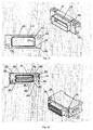
- Fig.6 is a stereogram of a connector with a connector interface according to an embodiment of the present invention.
- Fig.7 is a stereogram of a connector plug interface according to an embodiment of the present invention.
- Fig.8 is a front view of the front metal shell of the connector plug interface according to an embodiment of the present invention.
- Fig.9 is a stereogram and a front view of the insulator of the connector plug interface according to an embodiment of the present invention.
- Fig.10 is a stereogram of a connector socket interface according to an embodiment of the present invention.
- Fig.11 is a stereogram and a front view of the metal shell of the connector socket interface according to an embodiment of the present invention.
- Fig.12 is a stereogram and a front view of the insulator of the connector socket interface according to an embodiment of the present invention.
- the plurality of band-shaped recesses on the insulator of the connector socket interface can be arranged in parallel to each other, and the band-shaped recesses may be of equal or non-equal lengths; for example, if there are two band-shaped recesses provided on the insulator of the connector socket interface, the two band-shaped recesses can be of equal or non-equal lengths. If the individual band-shaped recesses are of non-equal lengths, misplugging of the connector interfaces can be effectively prevented.
- the plurality of band-shaped protrusions on the insulator of the connector plug interface are also arranged in parallel, corresponding to the band-shaped recesses respectively, and the length of the band-shaped protrusion corresponds to that of the band-shaped recess respectively.
- the band-shaped recesses are of non-equal lengths, they can be arranged symmetrically with reference to the center line of the coupling part of the connector socket interface; likewise, the band-shaped protrusions shall also be arranged symmetrically with reference to the center line of the coupling part of the connector plug interface.
- the coupling part of the connector interface according to an embodiment of the present invention is slightly wider than that of a connector interface with the same number of contacts in the prior art; however, the coupling part of the connector interface according to an embodiment of the present invention is much shorter than that of the connector interface in the prior art, so that the longitudinal section area of the coupling part of the connector interface according to an embodiment of the present invention is reduced.
- the longitudinal section of the coupling part of the connector interface is in rectangular shape, i.e., both of the longitudinal sections of the parts of the metal shell and the insulator of the connector socket interface and the metal shell and the insulator of the connector plug interface to be coupled with each other, respectively, are in rectangular shape.
- All of the four corners of said rectangle are fillets, and among them, the fillet radiuses of the two fillets corresponding to the diagonal of the rectangle are different, effectively avoiding misplugging of the connector interfaces when coupled.
- fasteners are provided on the connector interface, for example, screws are provided on the connector plug interface, and nuts matching with the screws are provided on the connector socket interface.
- the screws shall pass through the metal shell and the insulator of the connector plug interface, and, when the connector plug interface is coupled with the connector socket interface, are screwed up to the nuts on the connector socket interface, so that the connector interfaces are connected tightly in the plugging direction.
- said two screws can be provided at the upper and lower sides of the diagonal extension line of the coupling part of the connector plug interface, and the nuts on the connector socket interfaces are arranged at positions corresponding to those of the screws.
- At least one protrusion is provided between the metal shells of the coupling parts of the connector interfaces; said protrusion can be in semispherical shape and can be provided on the inner wall of the coupling part of metal shell of the connector socket interface; likewise, the protrusion can also be provided on the outer wall of the coupling part of metal shell of the connector plug interface.
- numerals can be labeled on the insulators of the connector socket interface and of the connector plug interface respectively; for example, numerals can be labeled beside the respective slots on the insulator of the connector socket interface in order of the positions of the metal contacts, and numerals can be labeled beside the respective slots on the insulator of the connector plug interface in order of the positions of the metal contacts, the numerals labeled on the insulator of the connector plug interface should correspond to the numerals labeled on the insulator of the connector socket interface; in this way, when the connector interfaces are coupled, whether the connector interfaces are coupled correctly can be judged by the corresponding numerals on the connector socket interface and the connector plug interface, even without the difference in fillet radius or the difference in length of the band-shaped recess.
- protrusions are provided on both the upper side and lower side of the base at the coupling part of the insulator of the connector socket interface; said protrusions can be 4 in number, two on each side.
- the protrusions can be in a wedge shape. Lugs of the same number are provided correspondingly on the metal shell of the connector socket interface, and, when the metal shell of the connector socket interface is connected with the insulator of the connector socket interface, the lugs are blocked at the wedge-shaped protrusions respectively.
- FIG.6 A stereogram of a connector with a connector interface according to an embodiment of the present invention is shown in Fig.6.
- the left view shows the connector side with connector plug interface 2; the right view shows the connector side with connector socket interface 4.
- the connector interface according to an embodiment of the present invention comprises connector socket interface 4 and connector plug interface 2.
- the connector plug interface 2 is connected with data cable 6 of multiple twisted pair of the connector; and the connector socket interface 4 is connected with the Printed Circuit Board in electronic equipment, such as DSLAM.
- the connector plug interface 2 mainly comprises metal shell 12 of the connector plug interface, insulator 34 of the connector plug interface, metal contacts 36, 38 and fixing screws 16, 18 of the connector plug interface.
- the connector plug interface 4 mainly comprises metal shell 14 of the connector socket interface, insulator 150 of the connector socket interface, metal contacts 35, 37 and fixing nuts 20, 22 of the connector socket interface.
- the connector plug interface 2 and the connector socket interface 4 are fully shielded when coupled with each other; interface shielding of the connector plug interface 2 is achieved by its metal shell 12, and interface shielding of the connector socket interface 4 is achieved by its metal shell 14.
- interface shielding of the connector plug interface 2 is achieved by its metal shell 12
- interface shielding of the connector socket interface 4 is achieved by its metal shell 14.
- FIG.7 A stereogram of a connector plug interface according to an embodiment of the present invention is shown in Fig.7.
- the body 24 of the connector plug interface mainly comprises front metal shell 13 of the connector plug interface, rear metal shell 32 of the connector plug interface, insulator 34 of the connector plug interface, metal contacts 36, 38 of the connector plug interface, and screws 16, 18 of the connector plug interface.
- band-shaped protrusions 204, 206 provided on the insulator 34 of the connector plug interface, the band-shaped protrusions 204, 206 being in parallel to each other, and the two band-shaped protrusions 204, 206 are different in length.
- FIG.8 A stereogram and a front view of front metal shell 13 of the connector plug interface are shown in Fig.8.
- the left view is the front view of the front metal shell 13; the right view is the stereogram of the front metal shell 13.
- the front metal shell 13 mainly comprises base 110 of the metal shell and coupling part 121 of the metal shell.
- the coupling part 121 of the metal shell is formed on the base 110 of the metal shell by punching, and the coupling part 121 of the metal shell is punched into a rectangle, comprising two longitudinal side walls 120 and two lateral side walls 128.
- the longitudinal side wall 120 and the lateral side walls 128 are connected with each other via a large fillet 130 and a small fillet 126.
- the fillet radius of the large fillet 130 is different from that of the small fillet 126.
- the coupling part 121 i.e., shielding shell 121 of metal shell of the connector plug interface
- the longitudinal section of the coupling part 121 i.e., shielding shell 121 of metal shell of the connector plug interface causes the longitudinal section of the coupling part 121 i.e., shielding shell 121 of metal shell of the connector plug interface to be asymmetric with reference to the horizontal center line, misplugging of the connector interface when coupled is prevented effectively.
- a plurality of circle protrusions 124 are provided on the inner walls 122 of the two longitudinal side wall 120, to ensure a certain retaining force in a direction other than the plugging direction when the connector plug interface the connector socket interface are coupled with each other, so that the connector plug interface and the connector socket interface are connected tightly with each other.
- Two screw holes 116, 118 corresponding to the screws are punched on the base 110 of the metal shell.
- the screw holes 116 and 118 are provided at two sides of the diagonal extension line of the rectangular longitudinal section of the coupling part 121 of the metal shell.
- the screw holes 116 and 118 are of the same size, and larger than the diameter of the screws.
- FIG.9 A stereogram and a front view of the insulator 34 of the connector plug interface are shown in Fig.9.
- the left view is the front view of the insulator 34; the right view is the stereogram of the insulator 34.
- the insulator 34 of the connector plug interface shown in Fig.9 can be made through injection molding.
- the longitudinal section of the base 202 of the upper and lower band-shaped protrusions 204 and 206 is in rectangular shape, and the four corners of the rectangle are fillets 208 and 218; the fillets 208 and 218 of the base 202 correspond to the large fillet 130 and the small fillet 126 of the front metal shell of the connector plug interface, respectively, i.e., the radius of the large fillet 208 is different from that of the small fillet 218, and the large fillet 208 and the small fillet 218 are asymmetrical in reference to the horizontal center line of the longitudinal section of the coupling part of insulator 34 of the connector plug interface.
- numerals 219 provided on the base 202 of the insulator 34 of the connector plug interface, and these numerals may indicate positions of the individual metal contacts of the connector plug interface.
- FIG.10 A stereogram of a connector socket interface is shown in Fig.10.
- the connector socket interface 4 provided in an embodiment of the present invention mainly comprises metal shell 14 of the connector socket interface, insulator 150 of the connector socket interface, fixing nuts 20, 22 of the connector socket interface, and metal contacts 35, 37 of the connector socket interface.
- the external thread portion of fixing nuts 20, 22 are connected with the fixing nuts 168, 170 having internal thread portion on the insulator 150; the fixing nuts 168, 170 can be of square shape in profile, and embedded into the insulator 150 at corresponding positions, there are two square holes 230 corresponding to the fixing nuts 168, 170 respectively, for embedding the fixing nuts 168, 170 provided at the corresponding positions of the insulator 150.
- FIG.11 A stereogram and a front view of the metal shell 14 of the connector socket interface are shown in Fig.11.
- the left view is the front view of metal shell 14; the right view is the stereogram of metal shell 14.
- Coupling part 270 of the metal shell 14 is formed on base 250 of the metal shell by punching, and the coupling part 270 of the metal shell is punched into a rectangle, comprising two longitudinal side walls 272 and two lateral side walls 276.
- the longitudinal side walls 272 and the lateral side walls 276 are connected with each other via two large fillets 278 and two small fillets 280 respectively.
- the radius of the large fillet 278 is different from that of the small fillet 280, and the large fillet 278 and the small fillet 280 are asymmetrical in reference to the horizontal center line of the longitudinal section of the metal shell 14 of the connector socket interface, effectively preventing misplugging of the connector interface when coupled.
- Two screw holes 252, 254 corresponding to the screws are also punched on the base 250 of the metal shell.
- the screw holes 252 and 254 are provided at two sides of the diagonal extension line of the rectangular longitudinal section of the coupling part 270 of the metal shell 14.
- the screw holes 252 and 254 are of the same size, and larger than the diameter of the screws 16 and 18 .
- FIG.12 A stereogram and a front view of the insulator 150 of the connector socket interface are shown in Fig.12.
- the left view is the front view of insulator 150; the right view is the stereogram of insulator 150.
- the insulator 150 of the connector socket interface can be made through injection molding.
- the insulator 150 comprises base 350 of the insulator and rectangular protrusion 352; the rectangular protrusion 352 is the coupling part of the insulator 150 of the connector socket interface.
- the longitudinal section of the rectangular protrusion 352 with the upper and lower band-shaped protrusions 354 and 256 is in rectangular shape, and the four corners of the rectangle are fillets 358 and 360, the fillets 358 and 360 corresponding to the large fillet 130 and the small fillet 126 of the front metal shell of the connector plug interface, respectively, i.e., the radius of the large fillet 358 is different from that of the small fillet 360, so that the coupling part of the insulator 150 of the connector socket interface is asymmetrical in reference to the horizontal center line.
- numerals 370 provided on the coupling part 352 of the insulator 150 of the connector socket interface, and these numerals 370 may indicate positions of the individual metal contacts of the connector socket interface.
- both the connector socket interface and the connector plug interface according to an embodiment of the present invention are 38 mm (L) x 14.6mm (W), then longitudinal section areas of the connector socket interface and the connector plug interface are 554.8 mm 2 , which is only 1/3 of the longitudinal section area of a connector interface in the prior art, 1512.9 mm 2 ; the footprint of each pair of contacts of the connector interface according to an embodiment of the present invention is 16.27 mm 2 , and the pin density is almost 3 times of that of a connector interface in the prior art.
- the volume of the electronic equipment is reduced significantly through increasing the pin density of the connector interface, thereby making the electronic equipment have a trend to miniature and high density.
Landscapes
- Details Of Connecting Devices For Male And Female Coupling (AREA)
- Use Of Switch Circuits For Exchanges And Methods Of Control Of Multiplex Exchanges (AREA)
- Communication Control (AREA)
- Connections Effected By Soldering, Adhesion, Or Permanent Deformation (AREA)
Claims (10)
- Steckverbinder-Schnittstelle, die eine Steckverbinder-Buchsen-Schnittstelle (4) und eine Steckverbinder-Stecker-Schnittstelle (2) umfasst, wobei die Steckverbinder-Buchsen-Schnittstelle (4) einen Isolator (150), eine auf dem Isolator (150) bereitgestellte bandförmige Aussparung (354, 356) und Metallkontakte (35, 37) umfasst, und die Steckverbinder-Stecker-Schnittstelle (2) einen Isolator (34) und einen auf dem Isolator (34) bereitgestellten bandförmigen Vorsprung (204, 206) und Metallkontakte (36, 38) umfasst, wobei die Steckverbinder-Buchsen-Schnittstelle (4) und die Steckverbinder-Stecker-Schnittstelle (2) miteinander gekoppelt werden können, wobei:die Steckverbinder-Buchsen-Schnittstelle (4) eine Vielzahl von bandförmigen Aussparungen (354, 356) aufweist, und eine Anzahl von Schlitzen (362, 364; 366, 368) vorhanden ist, welche die Metallkontakte (35, 37) der Steckverbinder-Buchsen-Schnittstelle (4) aufnehmen, die sowohl auf der oberen als auch auf der unteren Seitenwand jeder der bandförmigen Aussparungen (354, 356) bereitgestellt werden;die Steckverbinder-Stecker-Schnittstelle (2) eine Vielzahl von bandförmigen Vorsprüngen (204, 206) aufweist, die der Vielzahl der bandförmigen Aussparungen (354, 356) auf der Steckverbinder-Buchsen-Schnittstelle (4) entsprechen, und eine Anzahl von Schlitzen (210, 214; 212, 216) vorhanden ist, welche die Metallkontakte (36, 38) der Steckverbinder-Stecker-Schnittstelle (2) aufnehmen, die sowohl auf der oberen als auch auf der unteren Seitenwand jedes der bandförmigen Vorsprünge (204, 206) bereitgestellt werden,dadurch gekennzeichnet, dass die Steckverbinder-Buchsen-Schnittstelle (4) ein Metallgehäuse (14) umfasst, dass die Steckverbinder-Stecker-Schnittstelle (2) ein Metallgehäuse (12) umfasst, und dass die Vielzahl der bandförmigen Aussparungen (354, 356) auf dem Isolator (150) der Steckverbinder-Buchsen-Schnittstelle (4) eine unterschiedliche Länge haben und die bandförmigen Vorsprünge (204, 206) auf dem Isolator (34) der Steckverbinder-Stecker-Schnittstelle (2) jeweils in der Länge der Vielzahl der bandförmigen Aussparungen (354, 356) entsprechen.
- Steckverbinder-Schnittstelle gemäß Anspruch 1, wobeidie Vielzahl von bandförmigen Aussparungen (354, 356) parallel zueinander auf dem Isolator (150) der Steckverbinder-Buchsen-Schnittstelle (4) angeordnet sind;die Vielzahl von bandförmigen Vorsprüngen (204, 206) parallel zueinander auf dem Isolator (34) der Steckverbinder-Stecker-Schnittstelle (2) angeordnet sind und jeweils den bandförmigen Aussparungen (354, 356) entsprechen.
- Steckverbinder-Schnittstelle gemäß Anspruch 1, wobeidie Längs-Abschnitte der Teile des Metallgehäuses (14) und der Isolator (150) der Steckverbinder-Buchsen-Schnittstelle (4) und das Metallgehäuse (12) und der Isolator (34) der Steckverbinder-Stecker-Schnittstelle (2), die miteinander zu koppeln sind, alle eine Rechteckform haben.
- Steckverbinder-Schnittstelle gemäß Anspruch 3, wobei die vier Ecken des Rechtecks Ausrundungen sind.
- Steckverbinder-Schnittstelle gemäß Anspruch 4, wobeiunter den vier Ausrundungen die Rundungsradien von zwei Ausrundungen, die der Diagonale des Rechtecks entsprechen, sich voneinander unterscheiden.
- Steckverbinder-Schnittstelle gemäß einem der Ansprüche 1 bis 5, wobeian dem Metallgehäuse (14), dem Isolator (150) der Steckverbinder-Buchsen-Schnittstelle (4) und dem Metallgehäuse (12), dem Isolator (34) der Steckverbinder-Stecker-Schnittstelle (2) zueinander passende Befestigungsmittel (20, 22; 16, 18) bereitgestellt werden, und die Befestigungsmittel (20, 22; 16, 18) zur Befestigung benutzt werden, wenn die Steckverbinder-Buchsen-Schnittstelle (4) mit der Steckverbinder-Stecker-Schnittstelle (2) gekoppelt wird.
- Steckverbinder-Schnittstelle gemäß Anspruch 6, wobeidie Befestigungsmittel (20, 22; 16, 18) Schrauben (16, 18) und dazu passende Muttern (20, 22) umfassen;die Schrauben (16, 18) sowohl an der oberen als an der unteren Seite der diagonalen Verlängerungslinien des Längs-Abschnittes des Teils der Steckverbinder-Stecker-Schnittstelle (2) bereitgestellt werden, die mit der Steckverbinder-Buchsen-Schnittstelle (4) zu koppeln ist;die Muttern (20, 22) an der Steckverbinder-Buchsen-Schnittstelle (4) an Positionen bereitgestellt werden, die den Schrauben (16, 18) entsprechen.
- Steckverbinder-Schnittstelle gemäß einem der Ansprüche 1 bis 5, wobeiam Isolator (150) der Steckverbinder-Buchsen-Schnittstelle (4) Ziffern (370) an Positionen angebracht sind, die dessen Schlitzen (362, 364; 366, 368) entsprechen;am Isolator (34) der Steckverbinder-Stecker-Schnittstelle (2) Ziffern (219) an Positionen angebracht sind, die dessen Schlitzen (210, 214; 212, 216) entsprechen.
- Steckverbinder-Schnittstelle gemäß einem der Ansprüche 1 bis 5, wobeimindestens ein Vorsprung (124) zwischen den Positionen des Metallgehäuses (14) der Steckverbinder-Buchsen-Schnittstelle (4) und dem Metallgehäuse (12) der Steckverbinder-Stecker-Schnittstelle (2) bereitgestellt wird, wo diese durch Einstecken in Kontakt gebracht werden; undder Vorsprung (124) auf der Außenwand des Metallgehäuses (12) der Steckverbinder-Stecker-Schnittstelle (2) an einer Position bereitgestellt wird, an der das Metallgehäuse (12) der Steckverbinder-Stecker-Schnittstelle (2) und das Metallgehäuse (14) der Steckverbinder-Buchsen-Schnittstelle (4) miteinander zu koppeln sind, oder auf der Innenwand des Metallgehäuses (14) der Steckverbinder-Buchsen-Schnittstelle (4) an einer Position, an der das Metallgehäuse (14) der Steckverbinder-Buchsen-Schnittstelle (4) und das Metallgehäuse (12) der Steckverbinder-Stecker-Schnittstelle (2) miteinander zu koppeln sind.
- Steckverbinder-Schnittstelle gemäß einem der Ansprüche 1 bis 5, wobeiauf der Oberseite und der Unterseite des Isolators (150) der Steckverbinder-Buchsen-Schnittstelle (4) Vorsprünge bereitgestellt werden, und Laschen (256) auf dem Metallgehäuse (14) der Steckverbinder-Buchsen-Schnittstelle (4) bereitgestellt werden, wobei die Vorsprünge durch die Laschen blockiert werden.
Applications Claiming Priority (1)
| Application Number | Priority Date | Filing Date | Title |
|---|---|---|---|
| CNU2005200076420U CN2826733Y (zh) | 2005-03-11 | 2005-03-11 | 一种连接器接口 |
Publications (2)
| Publication Number | Publication Date |
|---|---|
| EP1701412A1 EP1701412A1 (de) | 2006-09-13 |
| EP1701412B1 true EP1701412B1 (de) | 2007-09-05 |
Family
ID=36499628
Family Applications (1)
| Application Number | Title | Priority Date | Filing Date |
|---|---|---|---|
| EP06003040A Expired - Lifetime EP1701412B1 (de) | 2005-03-11 | 2006-02-15 | Verbindungsschnittstelle |
Country Status (6)
| Country | Link |
|---|---|
| US (1) | US7713085B2 (de) |
| EP (1) | EP1701412B1 (de) |
| CN (1) | CN2826733Y (de) |
| AT (1) | ATE372595T1 (de) |
| DE (1) | DE602006000096T2 (de) |
| WO (1) | WO2006094465A1 (de) |
Families Citing this family (6)
| Publication number | Priority date | Publication date | Assignee | Title |
|---|---|---|---|---|
| CN2802767Y (zh) * | 2005-06-29 | 2006-08-02 | 华为技术有限公司 | 一种连接器插头 |
| DE102009052772B4 (de) * | 2008-12-01 | 2014-02-13 | Sumitomo Wiring Systems, Ltd. | Ein Verbinder |
| PL2290758T3 (pl) * | 2009-08-26 | 2017-04-28 | Wieland Electric Gmbh | Przemysłowe złącze wtykowe |
| WO2011140438A2 (en) * | 2010-05-07 | 2011-11-10 | Amphenol Corporation | High performance cable connector |
| CN102544912B (zh) * | 2011-10-31 | 2015-09-23 | 中航光电科技股份有限公司 | 具有锁紧结构的hdmi电连接器组件 |
| US10770839B2 (en) | 2018-08-22 | 2020-09-08 | Amphenol Corporation | Assembly method for a printed circuit board electrical connector |
Family Cites Families (17)
| Publication number | Priority date | Publication date | Assignee | Title |
|---|---|---|---|---|
| DE3318137C2 (de) * | 1983-05-18 | 1986-07-31 | Erni Elektroapparate Gmbh, 7321 Adelberg | Mehrpolige elektrische Steckvorrichtung |
| US4843714A (en) * | 1988-03-15 | 1989-07-04 | Amp Incorporated | Multiple line, automatic key programming and connector transfer system |
| JPH0817102B2 (ja) | 1988-07-15 | 1996-02-21 | 日本エー・エム・ピー株式会社 | 電気コネクタ |
| US5171161A (en) | 1991-05-09 | 1992-12-15 | Molex Incorporated | Electrical connector assemblies |
| US5955703A (en) * | 1996-02-28 | 1999-09-21 | Methode Electronics, Inc. | Circuitized electrical cable and method of assembling same |
| DE19816126A1 (de) * | 1998-04-09 | 1999-11-04 | Mannesmann Vdo Ag | Leiterplatte mit einem Kupplungselement einer Steckvorrichtung |
| US6785131B2 (en) * | 1999-10-28 | 2004-08-31 | Dell Products, L.P. | Computer system and documentation arrangement for guiding system installation |
| US6244895B1 (en) * | 1999-12-06 | 2001-06-12 | Hon Hai Precision Ind. Co., Ltd. | Connector assembly comprising coarse pitch connector and fine pitch connector |
| JP2002185167A (ja) * | 2000-12-18 | 2002-06-28 | Nec Corp | 電子部品の取付構造 |
| WO2002061892A1 (en) | 2001-01-29 | 2002-08-08 | Tyco Electronics Corporation | Connector interface and retention system for high-density connector |
| DE20106297U1 (de) * | 2001-04-10 | 2001-07-05 | Festo AG & Co, 73734 Esslingen | Elektrische Steckverbindungseinrichtung |
| US6540551B1 (en) * | 2001-12-05 | 2003-04-01 | Cosner Precision Electronics Co., Ltd. | Connector structure |
| US6752654B1 (en) * | 2003-04-11 | 2004-06-22 | Compal Electronics, Inc. | Serial advanced technology attachment connector |
| CN2651994Y (zh) | 2003-07-31 | 2004-10-27 | 富士康(昆山)电脑接插件有限公司 | 电连接器 |
| CN2664227Y (zh) | 2003-11-06 | 2004-12-15 | 华为技术有限公司 | 连接器 |
| JP2006049036A (ja) * | 2004-08-03 | 2006-02-16 | Tyco Electronics Amp Kk | ドッキングコネクタ |
| US7297019B2 (en) * | 2005-03-03 | 2007-11-20 | Tyco Electronics Corporation | Pluggable screwless wire connector system |
-
2005
- 2005-03-11 CN CNU2005200076420U patent/CN2826733Y/zh not_active Expired - Lifetime
-
2006
- 2006-02-15 EP EP06003040A patent/EP1701412B1/de not_active Expired - Lifetime
- 2006-02-15 DE DE602006000096T patent/DE602006000096T2/de not_active Expired - Lifetime
- 2006-02-15 AT AT06003040T patent/ATE372595T1/de not_active IP Right Cessation
- 2006-02-17 US US11/357,642 patent/US7713085B2/en active Active
- 2006-03-10 WO PCT/CN2006/000366 patent/WO2006094465A1/zh not_active Ceased
Also Published As
| Publication number | Publication date |
|---|---|
| DE602006000096D1 (de) | 2007-10-18 |
| EP1701412A1 (de) | 2006-09-13 |
| ATE372595T1 (de) | 2007-09-15 |
| WO2006094465A1 (fr) | 2006-09-14 |
| CN2826733Y (zh) | 2006-10-11 |
| US20080132111A1 (en) | 2008-06-05 |
| DE602006000096T2 (de) | 2008-01-03 |
| US7713085B2 (en) | 2010-05-11 |
Similar Documents
| Publication | Publication Date | Title |
|---|---|---|
| US20250062573A1 (en) | Electrical connector system | |
| US7497738B2 (en) | Electrical connector interacting between two different interfaces | |
| US10581189B2 (en) | Cable-to-board connector | |
| US20140073181A1 (en) | Ground unit and electrical connector using same | |
| CA2543474C (en) | Jack with modular mounting sleeve | |
| US7878855B2 (en) | Cable connector assembly with a front shell | |
| US20220271458A1 (en) | Differential pair module, connector, communications device, and shielding assembly | |
| EP1032089B1 (de) | Elektrische Verbinderanordnung | |
| US4717344A (en) | Connector for circuit boards | |
| US7029290B2 (en) | Cable connector assembly having improved mating port | |
| EP1701412B1 (de) | Verbindungsschnittstelle | |
| TWI608674B (zh) | 信號轉接裝置及轉接器總成 | |
| US20230187861A1 (en) | High density, high speed electrical connector | |
| TW201911685A (zh) | 轉接器總成及轉接器 | |
| US6821164B2 (en) | Connector assembly comprising a tab-receiving insulated spring sleeve and a dual contact with pairs of spaced apart contact members and tails | |
| CN1667882A (zh) | 电连接器组件 | |
| US7585189B2 (en) | Electrical connector | |
| WO2022057422A1 (zh) | 连接器组件及其制造方法和电子设备 | |
| US6361346B1 (en) | Connector system | |
| CN218182640U (zh) | 一种电连接器 | |
| CN201000942Y (zh) | 电连接器 | |
| CN223402030U (zh) | 多接口组件及有线传输设备 | |
| CA3158424C (en) | Differential pair module, connector, communications device, and shielding assembly | |
| CN214673115U (zh) | 一种新型电缆连接器 | |
| CN2757389Y (zh) | 电连接器 |
Legal Events
| Date | Code | Title | Description |
|---|---|---|---|
| PUAI | Public reference made under article 153(3) epc to a published international application that has entered the european phase |
Free format text: ORIGINAL CODE: 0009012 |
|
| 17P | Request for examination filed |
Effective date: 20060428 |
|
| AK | Designated contracting states |
Kind code of ref document: A1 Designated state(s): AT BE BG CH CY CZ DE DK EE ES FI FR GB GR HU IE IS IT LI LT LU LV MC NL PL PT RO SE SI SK TR |
|
| AX | Request for extension of the european patent |
Extension state: AL BA HR MK YU |
|
| 17Q | First examination report despatched |
Effective date: 20061227 |
|
| GRAP | Despatch of communication of intention to grant a patent |
Free format text: ORIGINAL CODE: EPIDOSNIGR1 |
|
| AKX | Designation fees paid |
Designated state(s): AT BE BG CH CY CZ DE DK EE ES FI FR GB GR HU IE IS IT LI LT LU LV MC NL PL PT RO SE SI SK TR |
|
| GRAS | Grant fee paid |
Free format text: ORIGINAL CODE: EPIDOSNIGR3 |
|
| GRAA | (expected) grant |
Free format text: ORIGINAL CODE: 0009210 |
|
| AK | Designated contracting states |
Kind code of ref document: B1 Designated state(s): AT BE BG CH CY CZ DE DK EE ES FI FR GB GR HU IE IS IT LI LT LU LV MC NL PL PT RO SE SI SK TR |
|
| REG | Reference to a national code |
Ref country code: GB Ref legal event code: FG4D |
|
| REG | Reference to a national code |
Ref country code: CH Ref legal event code: EP |
|
| REF | Corresponds to: |
Ref document number: 602006000096 Country of ref document: DE Date of ref document: 20071018 Kind code of ref document: P |
|
| REG | Reference to a national code |
Ref country code: IE Ref legal event code: FG4D |
|
| PG25 | Lapsed in a contracting state [announced via postgrant information from national office to epo] |
Ref country code: LT Free format text: LAPSE BECAUSE OF FAILURE TO SUBMIT A TRANSLATION OF THE DESCRIPTION OR TO PAY THE FEE WITHIN THE PRESCRIBED TIME-LIMIT Effective date: 20070905 Ref country code: FI Free format text: LAPSE BECAUSE OF FAILURE TO SUBMIT A TRANSLATION OF THE DESCRIPTION OR TO PAY THE FEE WITHIN THE PRESCRIBED TIME-LIMIT Effective date: 20070905 Ref country code: ES Free format text: LAPSE BECAUSE OF FAILURE TO SUBMIT A TRANSLATION OF THE DESCRIPTION OR TO PAY THE FEE WITHIN THE PRESCRIBED TIME-LIMIT Effective date: 20071216 |
|
| PG25 | Lapsed in a contracting state [announced via postgrant information from national office to epo] |
Ref country code: LI Free format text: LAPSE BECAUSE OF FAILURE TO SUBMIT A TRANSLATION OF THE DESCRIPTION OR TO PAY THE FEE WITHIN THE PRESCRIBED TIME-LIMIT Effective date: 20070905 Ref country code: CH Free format text: LAPSE BECAUSE OF FAILURE TO SUBMIT A TRANSLATION OF THE DESCRIPTION OR TO PAY THE FEE WITHIN THE PRESCRIBED TIME-LIMIT Effective date: 20070905 Ref country code: PL Free format text: LAPSE BECAUSE OF FAILURE TO SUBMIT A TRANSLATION OF THE DESCRIPTION OR TO PAY THE FEE WITHIN THE PRESCRIBED TIME-LIMIT Effective date: 20070905 Ref country code: AT Free format text: LAPSE BECAUSE OF FAILURE TO SUBMIT A TRANSLATION OF THE DESCRIPTION OR TO PAY THE FEE WITHIN THE PRESCRIBED TIME-LIMIT Effective date: 20070905 |
|
| NLV1 | Nl: lapsed or annulled due to failure to fulfill the requirements of art. 29p and 29m of the patents act | ||
| ET | Fr: translation filed | ||
| PG25 | Lapsed in a contracting state [announced via postgrant information from national office to epo] |
Ref country code: LV Free format text: LAPSE BECAUSE OF FAILURE TO SUBMIT A TRANSLATION OF THE DESCRIPTION OR TO PAY THE FEE WITHIN THE PRESCRIBED TIME-LIMIT Effective date: 20070905 Ref country code: BE Free format text: LAPSE BECAUSE OF FAILURE TO SUBMIT A TRANSLATION OF THE DESCRIPTION OR TO PAY THE FEE WITHIN THE PRESCRIBED TIME-LIMIT Effective date: 20070905 |
|
| REG | Reference to a national code |
Ref country code: CH Ref legal event code: PL |
|
| PG25 | Lapsed in a contracting state [announced via postgrant information from national office to epo] |
Ref country code: NL Free format text: LAPSE BECAUSE OF FAILURE TO SUBMIT A TRANSLATION OF THE DESCRIPTION OR TO PAY THE FEE WITHIN THE PRESCRIBED TIME-LIMIT Effective date: 20070905 Ref country code: GR Free format text: LAPSE BECAUSE OF FAILURE TO SUBMIT A TRANSLATION OF THE DESCRIPTION OR TO PAY THE FEE WITHIN THE PRESCRIBED TIME-LIMIT Effective date: 20071206 |
|
| PG25 | Lapsed in a contracting state [announced via postgrant information from national office to epo] |
Ref country code: SK Free format text: LAPSE BECAUSE OF FAILURE TO SUBMIT A TRANSLATION OF THE DESCRIPTION OR TO PAY THE FEE WITHIN THE PRESCRIBED TIME-LIMIT Effective date: 20070905 Ref country code: PT Free format text: LAPSE BECAUSE OF FAILURE TO SUBMIT A TRANSLATION OF THE DESCRIPTION OR TO PAY THE FEE WITHIN THE PRESCRIBED TIME-LIMIT Effective date: 20080206 Ref country code: CZ Free format text: LAPSE BECAUSE OF FAILURE TO SUBMIT A TRANSLATION OF THE DESCRIPTION OR TO PAY THE FEE WITHIN THE PRESCRIBED TIME-LIMIT Effective date: 20070905 Ref country code: IS Free format text: LAPSE BECAUSE OF FAILURE TO SUBMIT A TRANSLATION OF THE DESCRIPTION OR TO PAY THE FEE WITHIN THE PRESCRIBED TIME-LIMIT Effective date: 20080105 |
|
| PG25 | Lapsed in a contracting state [announced via postgrant information from national office to epo] |
Ref country code: RO Free format text: LAPSE BECAUSE OF FAILURE TO SUBMIT A TRANSLATION OF THE DESCRIPTION OR TO PAY THE FEE WITHIN THE PRESCRIBED TIME-LIMIT Effective date: 20070905 Ref country code: SE Free format text: LAPSE BECAUSE OF FAILURE TO SUBMIT A TRANSLATION OF THE DESCRIPTION OR TO PAY THE FEE WITHIN THE PRESCRIBED TIME-LIMIT Effective date: 20071205 |
|
| PLBE | No opposition filed within time limit |
Free format text: ORIGINAL CODE: 0009261 |
|
| STAA | Information on the status of an ep patent application or granted ep patent |
Free format text: STATUS: NO OPPOSITION FILED WITHIN TIME LIMIT |
|
| PG25 | Lapsed in a contracting state [announced via postgrant information from national office to epo] |
Ref country code: DK Free format text: LAPSE BECAUSE OF FAILURE TO SUBMIT A TRANSLATION OF THE DESCRIPTION OR TO PAY THE FEE WITHIN THE PRESCRIBED TIME-LIMIT Effective date: 20070905 |
|
| 26N | No opposition filed |
Effective date: 20080606 |
|
| PG25 | Lapsed in a contracting state [announced via postgrant information from national office to epo] |
Ref country code: MC Free format text: LAPSE BECAUSE OF NON-PAYMENT OF DUE FEES Effective date: 20080228 |
|
| PG25 | Lapsed in a contracting state [announced via postgrant information from national office to epo] |
Ref country code: IE Free format text: LAPSE BECAUSE OF NON-PAYMENT OF DUE FEES Effective date: 20080215 Ref country code: EE Free format text: LAPSE BECAUSE OF FAILURE TO SUBMIT A TRANSLATION OF THE DESCRIPTION OR TO PAY THE FEE WITHIN THE PRESCRIBED TIME-LIMIT Effective date: 20070905 |
|
| PG25 | Lapsed in a contracting state [announced via postgrant information from national office to epo] |
Ref country code: SI Free format text: LAPSE BECAUSE OF FAILURE TO SUBMIT A TRANSLATION OF THE DESCRIPTION OR TO PAY THE FEE WITHIN THE PRESCRIBED TIME-LIMIT Effective date: 20070905 |
|
| PG25 | Lapsed in a contracting state [announced via postgrant information from national office to epo] |
Ref country code: CY Free format text: LAPSE BECAUSE OF FAILURE TO SUBMIT A TRANSLATION OF THE DESCRIPTION OR TO PAY THE FEE WITHIN THE PRESCRIBED TIME-LIMIT Effective date: 20070905 |
|
| PG25 | Lapsed in a contracting state [announced via postgrant information from national office to epo] |
Ref country code: BG Free format text: LAPSE BECAUSE OF FAILURE TO SUBMIT A TRANSLATION OF THE DESCRIPTION OR TO PAY THE FEE WITHIN THE PRESCRIBED TIME-LIMIT Effective date: 20071205 |
|
| PG25 | Lapsed in a contracting state [announced via postgrant information from national office to epo] |
Ref country code: LU Free format text: LAPSE BECAUSE OF NON-PAYMENT OF DUE FEES Effective date: 20080215 Ref country code: HU Free format text: LAPSE BECAUSE OF FAILURE TO SUBMIT A TRANSLATION OF THE DESCRIPTION OR TO PAY THE FEE WITHIN THE PRESCRIBED TIME-LIMIT Effective date: 20080306 |
|
| PG25 | Lapsed in a contracting state [announced via postgrant information from national office to epo] |
Ref country code: TR Free format text: LAPSE BECAUSE OF FAILURE TO SUBMIT A TRANSLATION OF THE DESCRIPTION OR TO PAY THE FEE WITHIN THE PRESCRIBED TIME-LIMIT Effective date: 20070905 |
|
| GBPC | Gb: european patent ceased through non-payment of renewal fee |
Effective date: 20100215 |
|
| PG25 | Lapsed in a contracting state [announced via postgrant information from national office to epo] |
Ref country code: IT Free format text: LAPSE BECAUSE OF NON-PAYMENT OF DUE FEES Effective date: 20080229 |
|
| PG25 | Lapsed in a contracting state [announced via postgrant information from national office to epo] |
Ref country code: GB Free format text: LAPSE BECAUSE OF NON-PAYMENT OF DUE FEES Effective date: 20100215 |
|
| REG | Reference to a national code |
Ref country code: FR Ref legal event code: PLFP Year of fee payment: 11 |
|
| REG | Reference to a national code |
Ref country code: FR Ref legal event code: PLFP Year of fee payment: 12 |
|
| REG | Reference to a national code |
Ref country code: FR Ref legal event code: PLFP Year of fee payment: 13 |
|
| P01 | Opt-out of the competence of the unified patent court (upc) registered |
Effective date: 20230524 |
|
| PGFP | Annual fee paid to national office [announced via postgrant information from national office to epo] |
Ref country code: FR Payment date: 20241231 Year of fee payment: 20 |
|
| PGFP | Annual fee paid to national office [announced via postgrant information from national office to epo] |
Ref country code: DE Payment date: 20241231 Year of fee payment: 20 |
|
| REG | Reference to a national code |
Ref country code: DE Ref legal event code: R071 Ref document number: 602006000096 Country of ref document: DE |