EP1701417A1 - Connecteur avec pont de court-circuit et son procédé d'assemblage - Google Patents
Connecteur avec pont de court-circuit et son procédé d'assemblage Download PDFInfo
- Publication number
- EP1701417A1 EP1701417A1 EP06003049A EP06003049A EP1701417A1 EP 1701417 A1 EP1701417 A1 EP 1701417A1 EP 06003049 A EP06003049 A EP 06003049A EP 06003049 A EP06003049 A EP 06003049A EP 1701417 A1 EP1701417 A1 EP 1701417A1
- Authority
- EP
- European Patent Office
- Prior art keywords
- terminal
- joint
- contact
- housing
- terminal fittings
- Prior art date
- Legal status (The legal status is an assumption and is not a legal conclusion. Google has not performed a legal analysis and makes no representation as to the accuracy of the status listed.)
- Granted
Links
- 238000000034 method Methods 0.000 title claims description 8
- 238000003780 insertion Methods 0.000 claims abstract description 29
- 230000037431 insertion Effects 0.000 claims abstract description 29
- 238000006073 displacement reaction Methods 0.000 description 5
- 238000005192 partition Methods 0.000 description 2
- 238000005452 bending Methods 0.000 description 1
- 238000006243 chemical reaction Methods 0.000 description 1
- 238000010276 construction Methods 0.000 description 1
- 230000001419 dependent effect Effects 0.000 description 1
- 239000002184 metal Substances 0.000 description 1
- 230000000149 penetrating effect Effects 0.000 description 1
- 230000000717 retained effect Effects 0.000 description 1
- 238000000638 solvent extraction Methods 0.000 description 1
- 229920003002 synthetic resin Polymers 0.000 description 1
- 239000000057 synthetic resin Substances 0.000 description 1
Images


Classifications
-
- H—ELECTRICITY
- H01—ELECTRIC ELEMENTS
- H01R—ELECTRICALLY-CONDUCTIVE CONNECTIONS; STRUCTURAL ASSOCIATIONS OF A PLURALITY OF MUTUALLY-INSULATED ELECTRICAL CONNECTING ELEMENTS; COUPLING DEVICES; CURRENT COLLECTORS
- H01R31/00—Coupling parts supported only by co-operation with counterpart
- H01R31/08—Short-circuiting members for bridging contacts in a counterpart
- H01R31/085—Short circuiting bus-strips
-
- H—ELECTRICITY
- H01—ELECTRIC ELEMENTS
- H01R—ELECTRICALLY-CONDUCTIVE CONNECTIONS; STRUCTURAL ASSOCIATIONS OF A PLURALITY OF MUTUALLY-INSULATED ELECTRICAL CONNECTING ELEMENTS; COUPLING DEVICES; CURRENT COLLECTORS
- H01R31/00—Coupling parts supported only by co-operation with counterpart
- H01R31/08—Short-circuiting members for bridging contacts in a counterpart
Definitions
- the present invention relates to a joint connector and to a method of assembling it.
- a joint connector is known from Japanese Unexamined Patent Publication No. 2004-179032 .
- This connector is constructed such that a plurality of terminal fittings are mounted in a housing, a joint terminal having a plurality of contact portions is mounted in a holder, and the plurality of terminal fittings are shorted via the joint terminal when the respective contact portions are brought into contact with the corresponding terminal fittings.
- connection resistance is produced between the joint terminal and the terminal fittings when the terminal fittings are inserted into the housing and becomes a reaction force against the insertion.
- the wires may be buckled because of the above connection resistance, making it impossible to insert the terminal fittings.
- the present invention was developed in view of the above problem and an object thereof is to reduce the number of parts without hindering the insertion of terminal fittings into a housing.
- a joint connector comprising a housing, one or more terminal fittings to be at least partly accommodated in the housing, and a joint terminal to be brought into contact with the terminal fittings to electrically contact the terminal fittings to preferably short them, wherein the joint terminal is mounted in the housing and displaceable between a second position where the joint terminal at least partly enters respective insertion spaces for the terminal fittings to come into contact with the terminal fittings and a first position distanced from the second position in such a direction as to retract the joint terminal from the insertion spaces.
- the joint terminal Upon at least partly accommodating the terminal fittings into the housing, no or reduced insertion resistance resulting from the contact of the joint terminal and the terminal fittings is created if the joint terminal is held at the first position. Therefore, there is no likelihood of hindering the insertion of the terminal fittings.
- the joint terminal After being inserted, the joint terminal is connected to or contacted with the one or more terminal fittings, preferably the plurality of terminal fittings are shorted, if or when the joint terminal is displaced towards or to the second position (fully mounted position). Since the joint terminal is mounted in the housing, it is not necessary to provide means for holding the joint terminal in addition to the housing, thereby reducing the number of parts.
- a joint connector comprising:
- the invention according to claim 2 is characterized in that, in the joint connector according to claim 1, the leading ends of contact portions of the joint terminal with the terminal fittings are fitted in the leading ends of the terminal fittings with the joint terminal held at the first position or partial locking position.
- the contact portions of the joint terminal Since the leading ends of the contact portions of the joint terminal are fitted in the leading ends of the terminal fittings with the joint terminal held at the first position or partial locking position, the contact portions can be securely connected without colliding with the terminal fittings when the joint terminal is displaced to the second position or full locking position.
- the contact portion lightly touches resilient contact piece of the terminal fitting to such an extent as to hardly resiliently deform the resilient contact piece.
- the joint terminal comprises a main portion, preferably having a substantially rectangular shape long in transverse direction, and one or more narrow and long contact portions extending in an extending direction from the lateral edge of the main portion.
- the contact portions are continuous and/or substantially in flush with the main portion.
- one or more, preferably a pair of lateral locking pieces are formed to rise out of the plane containing the main portion and/or the contact portions to the front at the main portion, wherein a movement of the joint terminal toward the second position displacement is prevented by the contact of the locking pieces with corresponding portions of the housing, and/or one or more, preferably a pair of lateral first projections projecting outward substantially in the plane containing the main portion and/or the contact portions are formed at the main portion, wherein a movement in a direction to exit the joint terminal from the housing is prevented by the engagement of the first projections corresponding portions of the housing.
- the leading ends of contact portions of the joint terminal with the terminal fittings are fitted in the leading ends of the terminal fittings with the joint terminal held at the first position.
- the contact portion lightly touches resilient contact piece of the terminal fitting to such an extent as to hardly resiliently deform the resilient contact piece.
- a joint connector of this embodiment is provided with a housing 10, one or more, preferably a plurality of terminal fittings 20 and at least one joint terminal 30.
- the housing 10 is made e.g. of a synthetic resin and preferably substantially in the form of a flat block as a whole.
- One or more, preferably four cavities 11 preferably substantially narrow and long in forward and backward directions are formed preferably substantially side by side along transverse direction TD at one or more stages in the housing 10.
- the rear end of each cavity 11 makes a terminal insertion opening 12 in a terminal insertion surface, preferably substantially in the rear end surface, of the housing 10.
- a locking portion 13 integral or unitary to the housing 10 and resiliently deformable upward and downward (or in a direction at an angle different from 0° or 180°, preferably substantially normal to and/or intersecting with an inserting direction ID of the terminal fitting 20 into the cavity 20) is so formed in the cavity 11 preferably as to cantilever substantially forward along or at the bottom wall of the cavity 11.
- a guiding groove 14 preferably substantially in the form of a laterally long slit is formed in the front end surface of the housing 10.
- the guiding groove 14 is formed over an area preferably substantially corresponding to a transverse area where the one or more (e.g. four) cavities 11 are formed, and the lateral (upper and/or lower) surface(s) thereof is/are flat surface(s) substantially parallel to an inserting direction ID of the terminal fittings 20 into the housing 10.
- One or more (e.g. four) guiding holes 16 penetrating substantially in forward and backward directions from the rear wall surface of the guiding groove 14 to the front wall surfaces of the cavities 11 are formed in a partition wall 15 partitioning the guiding groove 14 and the cavities 11.
- the lateral (upper and/or lower) surface(s) of the guiding holes 16 are substantially continuous and/or substantially in flush with the corresponding surfaces of the guiding groove 14.
- a partial-locking or first slanted surface 17 sloped up or outward forward is formed at the front end (opening edge portion toward the front end surface of the housing 10) of the lateral (upper) surface of the guiding groove 14; one or more, preferably a pair of lateral (left and right) full locking or second portions 18 (preferably substantially in the form of steps) are formed at positions behind the partial-locking or first slanted surface 17 on the lateral (upper) surface of the guiding groove 14; and partial locking or first portions 19 (preferably substantially in the form of steps) are formed in the inner lateral (left and/or right) surface(s) of the guiding groove 14.
- Each terminal fitting 20 preferably is a female terminal fitting which is narrow and long in forward and backward directions as a whole and a front portion (preferably a substantially front half) of which serves as a tubular fitting portion 21.
- the interior of the tubular fitting portion 21 has an open front end, and a resilient contact piece 22 is provided in or at the tubular fitting portion 21.
- a locking hole or recess or step 23 engageable with a retaining projection 13a of the locking portion 13 is formed in the base or bottom wall of the tubular fitting portion 21.
- a rear portion (preferably a substantially rear half) of the terminal fitting 20 serves as a wire connecting portion 24 to be connected (preferably crimped or bent or folded into connection) with a wire 25, and the connected wire 25 extends preferably substantially backward.
- Such a terminal fitting 20 is at least partly inserted into the cavity 11 in the inserting direction ID; preferably substantially from behind, as described later.
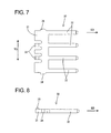
- the joint terminal 30 is made of a substantially flat conductive (preferably metal) sheet stamped or cut out into a specified (predetermined or predeterminable) shape and comprised of a main portion 31 preferably having a substantially rectangular shape long in transverse direction TD, and one or more (e.g. four) narrow and long contact portions 32 extending in an extending direction ED (preferably substantially backward) from the lateral (rear) edge of the main portion 31.
- the contact portions 32 are continuous and/or substantially in flush with the main portion 31.
- One or more, preferably a pair of lateral (left and right) locking pieces 33 are formed by cutting and bending to rise obliquely upward (or out of the plane containing the main portion 31 and/or the contact portions 32) to the front at or near the front edge of the main portion 31, and/or one or more, preferably a pair of lateral (left and right) partial locking or first projections 34 projecting outward substantially in flush (or substantially in the plane containing the main portion 31 and/or the contact portions 32) with the main portion 31 are formed at the (preferably substantially opposite) lateral (left and/or right) edge(s) of the main portion 31.
- Such a joint terminal 30 preferably is already mounted in the housing 10 before the terminal fittings 20 are at least partly inserted in the inserting direction ID into the housing 10.
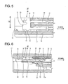
- the joint terminal 30 is at least partly inserted into the guiding groove 14 in a mounting direction MD (preferably substantially parallel to the extending direction ED and/or from front) and left at a partial locking position 1 P (as a preferred first position).
- the main portion 31 is located at a front-end area (opening-end area) at least partly in the guiding groove 14, and the rear ends of the respective contact portions 32 slightly project into the cavities 11 through the guiding holes 16.
- Displacements of the main portion 31 along vertical direction and/or transverse direction TD are prevented in the guiding groove 14, and displacements of the contact portions 32 along vertical direction and/or transverse direction TD are prevented in the guiding holes 16.
- a backward (toward a full locking position or second position 2P) displacement (or displacement in the mounting direction MD) of the joint terminal 30 is prevented by the contact of the locking pieces 33 with the partial-locking or first slanted surface 17 from front, and a forward (direction to exit the joint terminal 30 from the guiding groove 14 or substantially opposite to the mounting direction MD) is prevented by the engagement of the partial locking or first projections 34 with the partial locking or first portions 19 from behind. In this way, the joint terminal 30 is held or positioned or locked at the partial locking position 1P (first position).
- the joint terminal 30 held at the partial locking position 1P (first position) can be moved to the full locking position 2p (as a preferred second position) located more backward or in mounting direction MD (closer to the cavities 11) than the partial locking position 1 P (first position) by pushing the main portion 31 in the mounting direction MD and/or in the extending direction ED, preferably substantially from front.
- the joint terminal 30 is moved to the full locking position 2P (second position)
- the contact portions 32 at least partly enter the cavities 11 a longer distance or stroke than when the joint terminal 30 is at the partial locking position 1 P (first position).
- a backward movement of the joint terminal 30 is prevented by the contact of the rear edge of the main portion 31 with the front end surface of the partition wall 15 (rear end surface of the guiding groove 14), and a forward returning movement (toward the partial locking position or first position 1 P) of the joint terminal 30 is prevented by the engagement of the lateral (left and/or right) locking piece(s) 33 with the full locking or second portion(s) 18 preferably substantially from behind.
- the joint terminal 30 can be held at the full locking position 2P (second position).
- the joint terminal 30 Upon at least partly mounting the one or more terminal fittings 20 into the housing 10, the joint terminal 30 is mounted into the housing 10 in the mounting direction MD (being preferably substantially opposite to the inserting direction ID of the terminal fittings 20 into the housing 10), preferably substantially from front, and held at the partial locking position 1P (first position) beforehand.
- the (preferably each) terminal fitting 20 is at least partly inserted into the corresponding cavity 11 in the inserting direction ID; preferably substantially from behind.
- the tubular fitting portion 21 comes into contact with the retaining projection 13a to resiliently deform the locking portion 13 outwardly or substantially down.
- the locking portion 13 resiliently at least partly returns to engage the retaining projection 13a with the locking hole or recess 23, with the result that the terminal fitting 20 is held retained.
- the leading end of the corresponding contact portion 32 of the joint terminal 30 preferably is lightly fitted in the tubular fitting portion 21. At this time, preferably the contact portion 32 lightly touches the resilient contact piece 22 to such an extent as to hardly resiliently deform the resilient contact piece 22.
- the joint terminal 30 at the partial locking position 1 P (first position) is pushed to the full locking position 2P (second position) preferably substantially in the extending direction ED.
- the contact portions 32 gradually resiliently deform the resilient contact pieces 22 while coming substantially into sliding contact with the lateral (lower) surfaces of the resilient contact pieces 22.
- the resilient contact pieces 22 preferably are maximally resiliently deformed and/or the contact portions 32 and the resilient contact pieces 22 are electrically connected with contact pressures resulting from resilient restoring forces of the resilient contact pieces 22. In this way, the plurality of (e.g. four) terminal fittings 20 are shorted via the joint terminal 30.
- joint terminal 30 is at least partly mounted into or onto or on the housing 10 in this embodiment as described above, it is not necessary to provide means for holding the joint terminal 30 in addition to the housing 10, thereby reducing the number of parts.
- the joint terminal 30 mounted in the housing 10 is displaceable or movable between the full locking position 2P (second position) where the joint terminal 30 at least partly enters the cavities 11 as the insertion spaces for the terminal fittings 20 and the partial locking position 1 P (first position) distanced forward (toward the side opposite to the cavities 11) to substantially retract the joint terminal 30 from the cavities 11. Accordingly, upon at least partly accommodating the terminal fittings 20 into the housing 10, no or reduced insertion resistance resulting from the contact of the joint terminal 30 and the terminal fittings 20 is created if the joint terminal 30 is held at the partial locking position 1 P (first position). Therefore, there is no likelihood of hindering the insertion of the terminal fittings 20.
- the contact portions 32 of the joint terminal 30 preferably are at least partly fitted in the leading ends of the terminal fittings 20 with the joint terminal 30 held at the partial locking position 1 P (first position), the contact portions 32 can securely enter the tubular fitting portions 21 to be connected without colliding with the terminal fittings 20 when the joint terminal 30 is displaced to the full locking position 2P (second position).
Landscapes
- Connector Housings Or Holding Contact Members (AREA)
Applications Claiming Priority (1)
| Application Number | Priority Date | Filing Date | Title |
|---|---|---|---|
| JP2005069384A JP2006253017A (ja) | 2005-03-11 | 2005-03-11 | ジョイントコネクタ |
Publications (2)
| Publication Number | Publication Date |
|---|---|
| EP1701417A1 true EP1701417A1 (fr) | 2006-09-13 |
| EP1701417B1 EP1701417B1 (fr) | 2007-11-21 |
Family
ID=36263771
Family Applications (1)
| Application Number | Title | Priority Date | Filing Date |
|---|---|---|---|
| EP06003049A Expired - Lifetime EP1701417B1 (fr) | 2005-03-11 | 2006-02-15 | Connecteur avec pont de court-circuit et son procédé d'assemblage |
Country Status (4)
| Country | Link |
|---|---|
| US (1) | US7241168B2 (fr) |
| EP (1) | EP1701417B1 (fr) |
| JP (1) | JP2006253017A (fr) |
| DE (1) | DE602006000248T2 (fr) |
Cited By (2)
| Publication number | Priority date | Publication date | Assignee | Title |
|---|---|---|---|---|
| EP2164137A1 (fr) * | 2008-09-11 | 2010-03-17 | Sumitomo Wiring Systems, Ltd. | Connecteur de joint, terminal de joint, faisceau de câbles avec un connecteur de joint et son procédé d'assemblage |
| CN101904058B (zh) * | 2007-12-18 | 2013-03-27 | 株式会社自动网络技术研究所 | 连接器及使用该连接器的电线短路方法 |
Families Citing this family (43)
| Publication number | Priority date | Publication date | Assignee | Title |
|---|---|---|---|---|
| US7281950B2 (en) * | 2004-09-29 | 2007-10-16 | Fci Americas Technology, Inc. | High speed connectors that minimize signal skew and crosstalk |
| US7500871B2 (en) | 2006-08-21 | 2009-03-10 | Fci Americas Technology, Inc. | Electrical connector system with jogged contact tails |
| US7497736B2 (en) | 2006-12-19 | 2009-03-03 | Fci Americas Technology, Inc. | Shieldless, high-speed, low-cross-talk electrical connector |
| US7811100B2 (en) | 2007-07-13 | 2010-10-12 | Fci Americas Technology, Inc. | Electrical connector system having a continuous ground at the mating interface thereof |
| JP5033651B2 (ja) * | 2008-01-17 | 2012-09-26 | 株式会社オートネットワーク技術研究所 | ワイヤハーネス及びワイヤハーネス組立方法 |
| US8764464B2 (en) | 2008-02-29 | 2014-07-01 | Fci Americas Technology Llc | Cross talk reduction for high speed electrical connectors |
| DE102008036365A1 (de) * | 2008-08-05 | 2010-02-11 | Laakmann, Maik | ESM / AES Adapter für Harley Davidson Motorräder mit Elektrischen Soundmanagement ab Modelljahr 2007 -offen |
| US8545240B2 (en) | 2008-11-14 | 2013-10-01 | Molex Incorporated | Connector with terminals forming differential pairs |
| MY155071A (en) | 2008-12-12 | 2015-08-28 | Molex Inc | Resonance modifying connector |
| US9277649B2 (en) | 2009-02-26 | 2016-03-01 | Fci Americas Technology Llc | Cross talk reduction for high-speed electrical connectors |
| US8366485B2 (en) | 2009-03-19 | 2013-02-05 | Fci Americas Technology Llc | Electrical connector having ribbed ground plate |
| JP5428674B2 (ja) * | 2009-09-08 | 2014-02-26 | 株式会社オートネットワーク技術研究所 | アース接続装置及びこれを含むワイヤハーネス |
| US8267721B2 (en) | 2009-10-28 | 2012-09-18 | Fci Americas Technology Llc | Electrical connector having ground plates and ground coupling bar |
| US8616919B2 (en) | 2009-11-13 | 2013-12-31 | Fci Americas Technology Llc | Attachment system for electrical connector |
| JP5542238B2 (ja) * | 2010-03-25 | 2014-07-09 | 矢崎総業株式会社 | ジョイントコネクタ及びジョイントコネクタにおけるバスバーパターン識別方法 |
| JP5635390B2 (ja) * | 2010-12-21 | 2014-12-03 | 矢崎総業株式会社 | 抜け防止コネクタ |
| JP2012174432A (ja) * | 2011-02-18 | 2012-09-10 | Yazaki Corp | ジョイントコネクタ |
| JP2012174431A (ja) * | 2011-02-18 | 2012-09-10 | Yazaki Corp | ジョイントコネクタ及び端子半挿入検査方法 |
| EP2624034A1 (fr) | 2012-01-31 | 2013-08-07 | Fci | Dispositif de couplage optique démontable |
| USD727268S1 (en) | 2012-04-13 | 2015-04-21 | Fci Americas Technology Llc | Vertical electrical connector |
| USD727852S1 (en) | 2012-04-13 | 2015-04-28 | Fci Americas Technology Llc | Ground shield for a right angle electrical connector |
| US9257778B2 (en) | 2012-04-13 | 2016-02-09 | Fci Americas Technology | High speed electrical connector |
| US8944831B2 (en) | 2012-04-13 | 2015-02-03 | Fci Americas Technology Llc | Electrical connector having ribbed ground plate with engagement members |
| USD718253S1 (en) | 2012-04-13 | 2014-11-25 | Fci Americas Technology Llc | Electrical cable connector |
| JP2014002846A (ja) * | 2012-06-15 | 2014-01-09 | Yazaki Corp | ジョイントコネクタ拡張構造およびジョイントコネクタ |
| US9543703B2 (en) | 2012-07-11 | 2017-01-10 | Fci Americas Technology Llc | Electrical connector with reduced stack height |
| USD751507S1 (en) | 2012-07-11 | 2016-03-15 | Fci Americas Technology Llc | Electrical connector |
| JP6141612B2 (ja) * | 2012-09-21 | 2017-06-07 | 矢崎総業株式会社 | コネクタ |
| USD745852S1 (en) | 2013-01-25 | 2015-12-22 | Fci Americas Technology Llc | Electrical connector |
| USD720698S1 (en) | 2013-03-15 | 2015-01-06 | Fci Americas Technology Llc | Electrical cable connector |
| US8992251B2 (en) * | 2013-03-19 | 2015-03-31 | Delphi Technologies, Inc. | Electrical splice assembly |
| US9071197B2 (en) * | 2013-09-27 | 2015-06-30 | Qualcomm Incorporated | Harmonic rejective passive up converter |
| DE102014202316B4 (de) * | 2014-02-07 | 2021-04-01 | Te Connectivity Germany Gmbh | Kontaktträger mit einem Grundkörper und wenigstens einem Kontaktelement, Werkzeug zum Spritzgießen eines Kontaktträgers und Verfahren zur Herstellung eines Kontaktträgers |
| JP6206392B2 (ja) * | 2014-12-25 | 2017-10-04 | 株式会社オートネットワーク技術研究所 | ジョイントコネクタ |
| KR101755856B1 (ko) * | 2015-10-06 | 2017-07-19 | 현대자동차주식회사 | 차량용 다중 접지 커넥터 |
| US20170250504A1 (en) * | 2016-02-25 | 2017-08-31 | Hyundai Motor Company | Joint connector |
| CN109346865B (zh) | 2018-10-26 | 2020-07-07 | 湖南省泰格莱精密电子有限公司 | 大电流直流分散再汇流连接器 |
| US11621517B2 (en) * | 2018-12-27 | 2023-04-04 | Japan Aviation Electronics Industry, Limited | Connecting apparatus |
| JP7042403B2 (ja) * | 2018-12-28 | 2022-03-28 | 住友電装株式会社 | ジョイントコネクタ |
| JP7088110B2 (ja) | 2019-03-28 | 2022-06-21 | 株式会社オートネットワーク技術研究所 | ジョイントコネクタ |
| KR102812072B1 (ko) * | 2020-10-15 | 2025-05-22 | 현대자동차주식회사 | 커넥터 조립체 |
| KR102812094B1 (ko) | 2020-11-03 | 2025-05-22 | 현대자동차주식회사 | 커넥터 조립체 및 그 제조방법 |
| JP7725152B2 (ja) * | 2023-04-10 | 2025-08-19 | 矢崎総業株式会社 | コネクタ |
Citations (5)
| Publication number | Priority date | Publication date | Assignee | Title |
|---|---|---|---|---|
| EP0772258A1 (fr) * | 1995-11-02 | 1997-05-07 | Société SYLEA | Perfectionnements aux dispositifs de shuntage de plusieurs organes de contacts électriques |
| EP1030411A1 (fr) * | 1999-02-16 | 2000-08-23 | Sumitomo Wiring Systems, Ltd. | Connecteur de raccordement |
| EP1045483A2 (fr) * | 1999-04-13 | 2000-10-18 | Sumitomo Wiring Systems, Ltd. | Connecteur et dispositif d'assemblage pour ce connecteur |
| EP1054483A2 (fr) * | 1999-05-19 | 2000-11-22 | SUMITOMO WIRING SYSTEMS, Ltd. | Connecteur avec pont de court-circuit et procédé de fabrication du même |
| JP2004179032A (ja) | 2002-11-28 | 2004-06-24 | Sumitomo Wiring Syst Ltd | ジョイントコネクタ |
Family Cites Families (6)
| Publication number | Priority date | Publication date | Assignee | Title |
|---|---|---|---|---|
| US5201667A (en) * | 1990-06-27 | 1993-04-13 | Yazaki Corporation | Branch circuit structure |
| JP2563707Y2 (ja) * | 1990-08-07 | 1998-02-25 | 矢崎総業株式会社 | コネクタ |
| JP2903918B2 (ja) * | 1992-12-09 | 1999-06-14 | 住友電装株式会社 | ジョイントコネクタ |
| US5403204A (en) * | 1993-03-03 | 1995-04-04 | Sumitomo Wiring Systems, Ltd. | Joint connector |
| DE60026234T2 (de) * | 1999-04-13 | 2006-12-14 | Sumitomo Wiring Systems, Ltd., Yokkaichi | Verbinder |
| DE60027953T2 (de) * | 1999-04-13 | 2007-04-19 | Sumitomo Wiring Systems, Ltd., Yokkaichi | Wasserdichter Verbinder für elektrische Anschlusskontakte |
-
2005
- 2005-03-11 JP JP2005069384A patent/JP2006253017A/ja active Pending
-
2006
- 2006-02-15 EP EP06003049A patent/EP1701417B1/fr not_active Expired - Lifetime
- 2006-02-15 DE DE602006000248T patent/DE602006000248T2/de not_active Expired - Lifetime
- 2006-03-09 US US11/371,461 patent/US7241168B2/en not_active Expired - Fee Related
Patent Citations (5)
| Publication number | Priority date | Publication date | Assignee | Title |
|---|---|---|---|---|
| EP0772258A1 (fr) * | 1995-11-02 | 1997-05-07 | Société SYLEA | Perfectionnements aux dispositifs de shuntage de plusieurs organes de contacts électriques |
| EP1030411A1 (fr) * | 1999-02-16 | 2000-08-23 | Sumitomo Wiring Systems, Ltd. | Connecteur de raccordement |
| EP1045483A2 (fr) * | 1999-04-13 | 2000-10-18 | Sumitomo Wiring Systems, Ltd. | Connecteur et dispositif d'assemblage pour ce connecteur |
| EP1054483A2 (fr) * | 1999-05-19 | 2000-11-22 | SUMITOMO WIRING SYSTEMS, Ltd. | Connecteur avec pont de court-circuit et procédé de fabrication du même |
| JP2004179032A (ja) | 2002-11-28 | 2004-06-24 | Sumitomo Wiring Syst Ltd | ジョイントコネクタ |
Cited By (2)
| Publication number | Priority date | Publication date | Assignee | Title |
|---|---|---|---|---|
| CN101904058B (zh) * | 2007-12-18 | 2013-03-27 | 株式会社自动网络技术研究所 | 连接器及使用该连接器的电线短路方法 |
| EP2164137A1 (fr) * | 2008-09-11 | 2010-03-17 | Sumitomo Wiring Systems, Ltd. | Connecteur de joint, terminal de joint, faisceau de câbles avec un connecteur de joint et son procédé d'assemblage |
Also Published As
| Publication number | Publication date |
|---|---|
| US7241168B2 (en) | 2007-07-10 |
| EP1701417B1 (fr) | 2007-11-21 |
| DE602006000248D1 (de) | 2008-01-03 |
| US20060205270A1 (en) | 2006-09-14 |
| JP2006253017A (ja) | 2006-09-21 |
| DE602006000248T2 (de) | 2008-10-02 |
Similar Documents
| Publication | Publication Date | Title |
|---|---|---|
| EP1701417B1 (fr) | Connecteur avec pont de court-circuit et son procédé d'assemblage | |
| EP1923962B1 (fr) | Connecteur et son procédé de pré-assemblage | |
| EP1936749A1 (fr) | Organe de contact, connecteur et procédé de fabrication | |
| CN100566038C (zh) | 阴性端子接头,用于数个端子接头的坯料以及形成阴性端子接头的方法 | |
| EP1986284A2 (fr) | Connecteur et son procédé d'assemblage | |
| EP2009748A1 (fr) | Connecteur et son procédé d'assemblage | |
| EP2058905B1 (fr) | Connecteur | |
| EP2530787A2 (fr) | Connecteur et son procédé d'assemblage | |
| EP1271705B1 (fr) | Connecteur ayant un limiteur d' ouvrage pour un dispositif de retenue | |
| EP1094572B1 (fr) | Organe de contact et connecteur | |
| EP1635425B1 (fr) | Terminal de connexion | |
| EP1863135B1 (fr) | Connecteur et gabarit de déblocage de celui-ci | |
| EP1643599B1 (fr) | Organe de contact et connecteur avec un tel organe de contact | |
| EP2337158A1 (fr) | Connecteur | |
| EP1986288A1 (fr) | Borne de court-circuit, connecteur et son procédé d'assemblage | |
| EP1689034B1 (fr) | Contact à borne , connecteur le comprenant et procédé de fabrication | |
| KR100740849B1 (ko) | 커넥터 | |
| EP2913900A1 (fr) | Connecteur et procédé de connexion | |
| EP1261075B1 (fr) | Un connecteur étanche et un procédé pour son assemblage | |
| EP1693927B1 (fr) | Contact à borne , connecteur ayant un tel contact et procédé de fabrication | |
| JP4268074B2 (ja) | コネクタ | |
| US7306486B2 (en) | Connector | |
| EP1801926B1 (fr) | Connecteur et ensemble de connecteurs | |
| US7347748B2 (en) | Terminal fitting and connector provided therewith | |
| JP2007184188A (ja) | コネクタ |
Legal Events
| Date | Code | Title | Description |
|---|---|---|---|
| PUAI | Public reference made under article 153(3) epc to a published international application that has entered the european phase |
Free format text: ORIGINAL CODE: 0009012 |
|
| 17P | Request for examination filed |
Effective date: 20060223 |
|
| AK | Designated contracting states |
Kind code of ref document: A1 Designated state(s): AT BE BG CH CY CZ DE DK EE ES FI FR GB GR HU IE IS IT LI LT LU LV MC NL PL PT RO SE SI SK TR |
|
| AX | Request for extension of the european patent |
Extension state: AL BA HR MK YU |
|
| AKX | Designation fees paid |
Designated state(s): DE FR |
|
| GRAP | Despatch of communication of intention to grant a patent |
Free format text: ORIGINAL CODE: EPIDOSNIGR1 |
|
| GRAS | Grant fee paid |
Free format text: ORIGINAL CODE: EPIDOSNIGR3 |
|
| GRAA | (expected) grant |
Free format text: ORIGINAL CODE: 0009210 |
|
| AK | Designated contracting states |
Kind code of ref document: B1 Designated state(s): DE FR |
|
| REF | Corresponds to: |
Ref document number: 602006000248 Country of ref document: DE Date of ref document: 20080103 Kind code of ref document: P |
|
| ET | Fr: translation filed | ||
| PLBE | No opposition filed within time limit |
Free format text: ORIGINAL CODE: 0009261 |
|
| STAA | Information on the status of an ep patent application or granted ep patent |
Free format text: STATUS: NO OPPOSITION FILED WITHIN TIME LIMIT |
|
| 26N | No opposition filed |
Effective date: 20080822 |
|
| REG | Reference to a national code |
Ref country code: FR Ref legal event code: PLFP Year of fee payment: 11 |
|
| PGFP | Annual fee paid to national office [announced via postgrant information from national office to epo] |
Ref country code: DE Payment date: 20160209 Year of fee payment: 11 |
|
| PGFP | Annual fee paid to national office [announced via postgrant information from national office to epo] |
Ref country code: FR Payment date: 20160108 Year of fee payment: 11 |
|
| REG | Reference to a national code |
Ref country code: DE Ref legal event code: R119 Ref document number: 602006000248 Country of ref document: DE |
|
| REG | Reference to a national code |
Ref country code: FR Ref legal event code: ST Effective date: 20171031 |
|
| PG25 | Lapsed in a contracting state [announced via postgrant information from national office to epo] |
Ref country code: DE Free format text: LAPSE BECAUSE OF NON-PAYMENT OF DUE FEES Effective date: 20170901 Ref country code: FR Free format text: LAPSE BECAUSE OF NON-PAYMENT OF DUE FEES Effective date: 20170228 |