EP1701418A1 - Bougie d'allumage - Google Patents
Bougie d'allumage Download PDFInfo
- Publication number
- EP1701418A1 EP1701418A1 EP06004750A EP06004750A EP1701418A1 EP 1701418 A1 EP1701418 A1 EP 1701418A1 EP 06004750 A EP06004750 A EP 06004750A EP 06004750 A EP06004750 A EP 06004750A EP 1701418 A1 EP1701418 A1 EP 1701418A1
- Authority
- EP
- European Patent Office
- Prior art keywords
- metal shell
- insulator
- axial line
- tip face
- ground electrode
- Prior art date
- Legal status (The legal status is an assumption and is not a legal conclusion. Google has not performed a legal analysis and makes no representation as to the accuracy of the status listed.)
- Granted
Links
Images



Classifications
-
- H—ELECTRICITY
- H01—ELECTRIC ELEMENTS
- H01T—SPARK GAPS; OVERVOLTAGE ARRESTERS USING SPARK GAPS; SPARKING PLUGS; CORONA DEVICES; GENERATING IONS TO BE INTRODUCED INTO NON-ENCLOSED GASES
- H01T13/00—Sparking plugs
- H01T13/02—Details
- H01T13/14—Means for self-cleaning
-
- H—ELECTRICITY
- H01—ELECTRIC ELEMENTS
- H01T—SPARK GAPS; OVERVOLTAGE ARRESTERS USING SPARK GAPS; SPARKING PLUGS; CORONA DEVICES; GENERATING IONS TO BE INTRODUCED INTO NON-ENCLOSED GASES
- H01T13/00—Sparking plugs
- H01T13/20—Sparking plugs characterised by features of the electrodes or insulation
Definitions
- the difference in the distances between the position of the axial line of the insulator and the two inside end points does not vary to a large extent.
- the influence of the electric field concentration around the inside end points is not influential, even if the position of the axial line of the insulator is moved in the direction perpendicular to the straight line connecting the center of the inner circle of the tip face of the metal shell and the center of the end face of the one end portion of the ground electrode on the side where the position of the axial line of the insulator is distant from the ground electrode in the region that is located inside the inner circle of the tip face of the metal shell and in which the relationship A > B is satisfied.
- the influence of the electric field concentration around the inside end points can be made small even if the position of the axial line of the insulator is moved in the above-mentioned manner.
- the probability of lateral sparking can be made sufficiently low even if the allowance of the positioning between the metal shell and the insulator in manufacture of the spark plug is set large.
- the inside end points of the ground electrode may be determined by using a projection obtained by projecting, onto the plane including the tip face of the metal shell, a portion of the ground electrode that has clear inside end points in a transverse cross section. More specifically, a projection may be used which is obtained by projecting, onto the above plane, inside end points in a portion located on the tip side of a melted portion between the metal shell and the ground electrode (e.g., an imaginary cross section of the ground electrode that is set apart from the tip face of the metal shell by 1 mm).
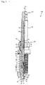
- the ground electrode 30 is made of a metal of high corrosion resistance, an example of which is a nickel alloy such as INCONEL (trade name) 600 or 601.
- the ground electrode 30 is approximately rectangular in transverse cross section, and its one end face 35 on the side of base portion 32 is joined to the tip face 57 of the metal shell 50 by welding.
- the ground electrode 30 is bent so that part of an inside surface 33 corresponding to the other end portion (tip portion 31) of the ground electrode 30 is opposed to the tip portion 22 of the center electrode 20.
- a noble metal chip 91 is joined to the inside surface 33 of the tip portion 31 in such manner that its axis coincides with the axis of the center electrode 20. As a result, a spark discharge gap is formed between the noble metal chips 90 and 91 which are opposed to one another.
- Annular ring members 6 and 7 are interposed between the tool engagement portion 51 of the metal shell 50 and the tail-side barrel portion 18 of the insulator 10, and the space between the two rings 6 and 7 is charged with talc powder 9.
- a crimping portion 53 is formed in the rear of the tool engagement portion 51. The insulator 10 is pressed toward the tip side in the metal shell 50 via the ring members 6 and 7 and the talc powder 9 by crimping the crimping portion 53.
- the step portion 15 of the insulator 10 between the tip-side barrel portion 17 and the leg portion 13 is supported, via a packing 80, by a step portion 56 which is formed in the inner circumferential surface of the metal shell 50, whereby the metal shell 50 and the insulator 10 are integrated with one another. Airtightness between the metal shell 50 and the insulator 10 is secured by the packing 80 to prevent an outflow of combustion gas.
- a brim portion 54 is formed at a central position of the metal shell 50, and a gasket 5 is inserted so as to be located in the rear of (in Fig. 5, over) the screw portion 52, that is, on a seat face 55 of the brim portion 54.
- spark plugs in which the nominal diameter of the metal shell is larger than M12 lateral sparking is not prone to occur due to an increase in the strength of an electric field around the ground electrode. This is because the distance (clearance) between the outer circumferential surface (14) of the insulator 10 and the inner circumferential surface (58) of the metal shell is sufficiently long and the insulation resistance is large there.
- the embodiment is directed to spark plugs (100) in which the nominal diameter of the screw portion (52) as a measure of the spark plug size is smaller than or equal to M12.
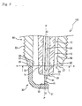
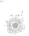
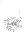
- Fig. 3 is a sectional view of a tip portion of the spark plug 100 taken along a two-dot chain line X-X in Fig. 2 and viewed from the direction indicated by the arrows.
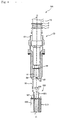
- Fig. 4 illustrates a technique of fixing the metal shell 50 and the insulator 10 to one another in an off-axis state.
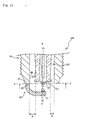
- Fig. 5 is an enlarged sectional view of a part of the spark plug 100 in which a welding burr bridging the metal shall 50 and the ground electrode 30 is not completely removed.
- Fig. 3 is a sectional view of a tip portion of the spark plug 100 taken along a two-dot chain line X-X in Fig. 2 and viewed from the direction indicated by the arrows.
- Fig. 4 illustrates a technique of fixing the metal shell 50 and the insulator 10 to one another in an off-axis state.
- Fig. 5 is an enlarged sectional view of a part of the spark plug 100 in which a welding burr bridging
- the axial line O of the insulator 10 deviates from the axial line P of the metal shell 50 to the side opposite to the side where the ground electrode 30 is joined to the metal shell 50. More specifically, the following positional relationship is established.
- Q denotes the center of the base-portion-30-side end face 35 of the ground electrode 30 which is joined to the tip face 57 of the metal shell 50.
- the transverse cross section of the ground electrode 30, that is, the end face 35 is approximately rectangular, the intersection point of the diagonals of the rectangle is denoted by Q.
- the center Q of the end face 35 of the ground electrode 30 may be determined by projecting that portion of the ground electrode 30 which has a clear sectional shape onto a plane including the tip face 57 of the metal shell 50 (i.e., an X-X plane including the cross section of the spark plug 100 taken along the two-dot chain line X-X in Fig. 2 and viewed from the direction indicated by the arrows).
- the center of the inner circle (denoted by L in Fig. 3) of the tip face 57 of the metal shell 50 coincides with the intersection point of the axial line P and the X-X plane. Therefore, the line passing through the center Q and the axial line P in the X-X plane is denoted by Y-Y.
- the distance between the outer circumferential surface 14 of the insulator 10 and the inner circle L of the tip face 57 of the metal shell 50 on the line Y-Y on the ground electrode 30 side of the axial line P is represented by A.
- the insulator 10 is formed so that its cross section perpendicular to the axial line O assumes a perfect circle.
- the metal shell 50 is formed so that its cross section perpendicular to the axial line P assumes a perfect circle. Therefore, in a manufacturing process of the spark plug 100, it is appropriate to crimp the crimping portion 53 in a state that the metal shell 50 and the insulator 10 are tentatively fixed to one another after being positioned with respect to one another so that the position of the axial line O is located on the side of the position of the axial line P opposite the ground electrode 40 on the line Y-Y.
- the above-mentioned relationship A > B can be satisfied by the above procedure, that is, by positioning the metal shell 50 and the insulator 10 with respect to one another using the axial lines P and O as references.
- one specific method for positioning the metal shell 50 and the insulator 10 at the time of crimping is a method using a positioning member 500.
- the positioning member 500 is cylindrical and has a through-hole 520.
- An outer circumferential surface 501 engages the inner circumferential surface 58 of the metal shell 50, and an inner circumferential surface 502 of the through-hole 520 engages the outer circumferential surface 14 of the insulator 10.
- the positioning member 500 is configured so that the positional relationship between the axis of the cylindrical shape of the outer circumferential surface 501 and the axis of the cylindrical shape of the inner circumferential surface 502 is the same as that of the axial line P of the crimped metal shell 50 and the axial line O of the insulator 10.
- the seat 510 has a cut portion 530 which extends parallel with the axial direction.
- the ground electrode 30 which is joined to the metal shell 50 engages the cut portion 530, whereby the direction of deviation between the axis of the cylindrical shape of the outer circumferential surface 501 and the axis of the cylindrical shape of the inner circumferential surface 502 is made equal to that between the axial line P of the crimped metal shell 50 and the axial line O of the insulator 10.
- the outer circumferential surface 501 engages the inner circumferential surface 58 of the metal shell 50 while the ground electrode 30 engages the cut portion 530 of the seat 510.
- the packing 80 and the insulator 10 are inserted from the rear side of the metal shell 50, and the tip-side portion of the outer circumferential surface 14 of the insulator 10 engages the inner circumferential surface 502 of the through-hole 520 of the positioning member 500.
- the crimping portion 53 of the metal shell 50 is crimped, whereby the metal shell 50 and the insulator 10 are fixed to and integrated with one another. In this manner, the spark plug 100 in which the axial line P of the metal shell 50 and the axial line O of the insulator 10 deviate from one another and in which the relationship A > B is satisfied can be manufactured easily.
- the projection length G of the welding projection 85 is shorter than or equal to 0.1 mm, a clearance as required in the embodiment in order to arrange the metal shell 50 and the insulator 10 so that their axial lines P and O deviate from one another can be secured. If the projection length G of the welding projection 85 is greater than 0.1 mm, a spark discharge may occur between the tip portion of the welding projection 85 and the outer circumferential surface 14 of the insulator 10 when smoldering has occurred.
- the distance between the tip of the welding projection 85 and the outer circumferential surface 14 of the insulator 10 on the above-mentioned line Y-Y is represented by D.
- the distance D is desirably greater than the distance B, more specifically, the difference between the distances D and B is desirably from 0.1 to 0.3 mm.
- the transverse cross section of the ground electrode 30 is approximately rectangular, its adjoining side surfaces form a ridge line.
- the electric field strength tends to be high around such sharp edges.
- the positional relationship between the metal shell 50 and the insulator 10 is determined in the following manner.
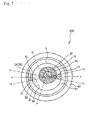
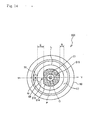
- the two end points of the inside line segment closest to the axial line P of the metal shell 50 among the four line segments that form the outline of the end face 35 of the base portion 32 of the ground electrode 30 are denoted by S1 and S2.
- the inside end points S1 and S2 are points obtained by projecting, onto the X-X plane, the two ridge lines formed by the inside surface 33 and the two adjacent side surfaces of the ground electrode 30, and are points where electric field concentration tends to occur.
- the two straight lines passing through the two inside end points S 1 and S2 and the center of the inner circle L of the tip face 57 of the metal shell 50 are denoted by T1 and T2, respectively.
- the region inside the inner circle L of the tip face 57 of the metal shell 50 is divided into four sectors by the straight lines T1 and T2.
- the acute-angled sector that is defined by the straight lines T1 and T2 and part of the inner circle L, and which is located on the side of the position of the axial line P opposite the ground electrode 30, is denoted by U (hatched in Fig. 6).
- the difference in distance between the position of the axial line O and the inside end point S1 and the distance between the position of the axial line O and the inside end point S2 does not vary to a large extent even if the position of the axial line O moves in the direction perpendicular to the line Y-Y so as to come closer to one of the inside end points S 1 and S2.
- a state in which the position of the axial line O deviates in the direction perpendicular to the line Y-Y so as to be located outside the range whose length is equal to the distance between the inside end points S1 and S2 is not preferred. This is because the distance between the inner circumferential surface 58 of the metal shell 50 and the outer circumferential surface 14 of the insulator 10 is small on the side of the deviation.
- the position of the axial line O of the insulator 10 is close to the inside end points S1 and S2 in the one, more distant from the ground electrode 30, of the two regions formed by dividing the inner circle L of the tip face 57 of the metal shell 50 by the straight line that passes through the position of the axial line P of the metal shell 50 and is perpendicular to the line Y-Y, the position of the axial line O is set at a position where the distances between the position of the axial line O and the inside end points S1 and S2 are approximately the same even if it deviates in the direction perpendicular to the line Y-Y.
- the position of the axial line O of the insulator 10 is away from the inside end points S 1 and S2 in the one, more distant from the ground electrode 30, of the two regions formed by dividing the inner circle L of the tip face 57 of the metal shell 50 by the straight line that passes through the position of the axial line P of the metal shell 50 and is perpendicular to the line Y-Y, the position of the axial line O is allowed to deviate in the direction perpendicular to the line Y-Y as long as it is located within a range whose length is equal to the distance between the inside end points S and S2.
- the noble metal chip 91 at a position that deviates toward the tip of the ground electrode 30 from the joining position (reference joining position) of the noble metal chip on the ground electrode in a conventional spark plug (i.e., the joining position with which the axial line of the noble metal chip coincides with the axial line P of the metal shell when the ground electrode is bent) by the deviation between the axial lines P and O (i.e., (A - B)/2 (see Fig. 3)).
- the cross section of the insulator 10 taken perpendicularly to the axial line O need not be a perfect circle.
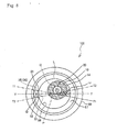
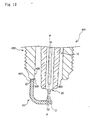
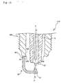
- a tip portion of an insulator 510 has a thin portion 519 which is located on the side of the ground electrode 30.
- E represent the distance between the inner circle L of the tip face 57 of the metal shell 50 and the thin portion 519 of the insulator 510 on the line Y-Y passing through the center Q of the ground electrode 30 and the axial line P of the metal shell 50 in the X-X plane including the tip face 57 of the metal shell 50.
- the spark plug 500 may be constructed so that the distance E is longer than the distance B as mentioned in the embodiment.
- the durability or the insulation performance may lower due to the thin portion, etc. Therefore, as in the embodiment, the axial line of the insulator is arranged so as to deviate from that of the metal shell.
- the invention can be applied to spark plugs for internal combustion engines.
Landscapes
- Spark Plugs (AREA)
Applications Claiming Priority (1)
| Application Number | Priority Date | Filing Date | Title |
|---|---|---|---|
| JP2005063747 | 2005-03-08 |
Publications (2)
| Publication Number | Publication Date |
|---|---|
| EP1701418A1 true EP1701418A1 (fr) | 2006-09-13 |
| EP1701418B1 EP1701418B1 (fr) | 2011-08-17 |
Family
ID=36568721
Family Applications (1)
| Application Number | Title | Priority Date | Filing Date |
|---|---|---|---|
| EP06004750A Expired - Lifetime EP1701418B1 (fr) | 2005-03-08 | 2006-03-08 | Bougie d'allumage |
Country Status (3)
| Country | Link |
|---|---|
| US (1) | US7557496B2 (fr) |
| EP (1) | EP1701418B1 (fr) |
| CN (1) | CN100505448C (fr) |
Cited By (3)
| Publication number | Priority date | Publication date | Assignee | Title |
|---|---|---|---|---|
| EP2187489A4 (fr) * | 2007-08-08 | 2013-06-26 | Ngk Spark Plug Co | Bougie d'allumage et procede de fabrication associe |
| DE102018213867B4 (de) | 2017-08-18 | 2024-05-02 | Niterra Co., Ltd. | Zündkerze |
| DE102018119732B4 (de) | 2017-08-18 | 2024-07-04 | Niterra Co., Ltd. | Zündkerze |
Families Citing this family (19)
| Publication number | Priority date | Publication date | Assignee | Title |
|---|---|---|---|---|
| JP4625416B2 (ja) * | 2006-03-21 | 2011-02-02 | 日本特殊陶業株式会社 | スパークプラグ |
| JP4762109B2 (ja) * | 2006-10-24 | 2011-08-31 | 株式会社日本自動車部品総合研究所 | 内燃機関用スパークプラグ |
| JP4369963B2 (ja) * | 2007-06-22 | 2009-11-25 | 日本特殊陶業株式会社 | スパークプラグ用絶縁体の検査方法 |
| JP2009004257A (ja) * | 2007-06-22 | 2009-01-08 | Nippon Soken Inc | スパークプラグ取付構造 |
| US8013617B2 (en) * | 2008-03-10 | 2011-09-06 | Ngk Spark Plug Co., Ltd. | Test method and apparatus for spark plug ceramic insulator |
| US20090306817A1 (en) * | 2008-06-09 | 2009-12-10 | The Coca-Cola Company | Virtual Vending Machine |
| JP5099858B2 (ja) * | 2008-11-04 | 2012-12-19 | 日本特殊陶業株式会社 | スパークプラグ及びスパークプラグの製造方法 |
| CN101944707B (zh) * | 2009-07-06 | 2013-03-27 | 日本特殊陶业株式会社 | 火花塞 |
| US8671901B2 (en) | 2009-11-30 | 2014-03-18 | GM Global Technology Operations LLC | Excess demand voltage relief spark plug for vehicle ignition system |
| CN103222139B (zh) * | 2010-11-22 | 2014-09-17 | 日本特殊陶业株式会社 | 火花塞的制造方法及制造装置 |
| EP2698886B1 (fr) * | 2011-04-14 | 2017-08-09 | Ngk Spark Plug Co., Ltd. | Procédé permettant de fabriquer une bougie d'allumage |
| CN103703638B (zh) * | 2011-09-01 | 2015-12-09 | 日本特殊陶业株式会社 | 火花塞 |
| JP5955668B2 (ja) * | 2012-07-03 | 2016-07-20 | 株式会社日本自動車部品総合研究所 | 点火プラグ |
| JP5715652B2 (ja) * | 2013-01-11 | 2015-05-13 | 日本特殊陶業株式会社 | スパークプラグ及びその製造方法 |
| JP5878880B2 (ja) * | 2013-02-13 | 2016-03-08 | 日本特殊陶業株式会社 | スパークプラグおよびその製造方法 |
| JP5970049B2 (ja) * | 2013-11-28 | 2016-08-17 | 日本特殊陶業株式会社 | スパークプラグおよびその製造方法 |
| JP5922087B2 (ja) * | 2013-12-24 | 2016-05-24 | 日本特殊陶業株式会社 | スパークプラグ |
| JP6342446B2 (ja) * | 2016-05-18 | 2018-06-13 | 日本特殊陶業株式会社 | スパークプラグ用の接地側電極用棒材付きの筒状主体金具の製造方法、及びスパークプラグの製造方法 |
| JP6632576B2 (ja) * | 2017-07-14 | 2020-01-22 | 日本特殊陶業株式会社 | 点火プラグ |
Citations (3)
| Publication number | Priority date | Publication date | Assignee | Title |
|---|---|---|---|---|
| JPH09256939A (ja) | 1996-03-22 | 1997-09-30 | Mitsubishi Motors Corp | 点火プラグ及びその取り付け構造 |
| JP2004207219A (ja) | 2002-12-10 | 2004-07-22 | Denso Corp | スパークプラグ |
| EP1601073A1 (fr) | 2004-05-27 | 2005-11-30 | Nissan Motor Co., Ltd. | Bougie d'allumage |
Family Cites Families (12)
| Publication number | Priority date | Publication date | Assignee | Title |
|---|---|---|---|---|
| JPS4985428A (fr) * | 1972-12-22 | 1974-08-16 | ||
| JP4100725B2 (ja) * | 1995-03-16 | 2008-06-11 | 株式会社デンソー | 内燃機関用スパークプラグ |
| JPH10189212A (ja) * | 1995-11-15 | 1998-07-21 | Ngk Spark Plug Co Ltd | 多極スパークプラグ |
| JP3272615B2 (ja) * | 1995-11-16 | 2002-04-08 | 日本特殊陶業株式会社 | 内燃機関のスパークプラグ |
| JP3340349B2 (ja) * | 1997-04-15 | 2002-11-05 | 日本特殊陶業株式会社 | スパークプラグ |
| JPH1154240A (ja) | 1997-07-31 | 1999-02-26 | Ngk Spark Plug Co Ltd | スパークプラグ |
| JP4505993B2 (ja) * | 2001-01-18 | 2010-07-21 | 株式会社デンソー | スパークプラグの製造方法 |
| JP2003142227A (ja) * | 2001-08-22 | 2003-05-16 | Denso Corp | スパークプラグおよびその製造方法 |
| JP3795374B2 (ja) * | 2001-10-31 | 2006-07-12 | 日本特殊陶業株式会社 | スパークプラグ |
| DE10214167A1 (de) | 2002-03-28 | 2003-10-09 | Bosch Gmbh Robert | Brennstoffeinspritzventil-Zündkerze-Kombination |
| JP3887010B2 (ja) * | 2002-10-25 | 2007-02-28 | 日本特殊陶業株式会社 | 内燃機関用スパークプラグ |
| US7187110B2 (en) * | 2003-09-27 | 2007-03-06 | Ngk Spark Plug Co., Ltd. | Spark plug |
-
2006
- 2006-03-07 US US11/368,629 patent/US7557496B2/en not_active Expired - Lifetime
- 2006-03-08 EP EP06004750A patent/EP1701418B1/fr not_active Expired - Lifetime
- 2006-03-08 CN CNB2006100581753A patent/CN100505448C/zh not_active Expired - Lifetime
Patent Citations (3)
| Publication number | Priority date | Publication date | Assignee | Title |
|---|---|---|---|---|
| JPH09256939A (ja) | 1996-03-22 | 1997-09-30 | Mitsubishi Motors Corp | 点火プラグ及びその取り付け構造 |
| JP2004207219A (ja) | 2002-12-10 | 2004-07-22 | Denso Corp | スパークプラグ |
| EP1601073A1 (fr) | 2004-05-27 | 2005-11-30 | Nissan Motor Co., Ltd. | Bougie d'allumage |
Non-Patent Citations (2)
| Title |
|---|
| PATENT ABSTRACTS OF JAPAN vol. 1998, no. 01 30 January 1998 (1998-01-30) * |
| PATENT ABSTRACTS OF JAPAN vol. 2003, no. 12 5 December 2003 (2003-12-05) * |
Cited By (3)
| Publication number | Priority date | Publication date | Assignee | Title |
|---|---|---|---|---|
| EP2187489A4 (fr) * | 2007-08-08 | 2013-06-26 | Ngk Spark Plug Co | Bougie d'allumage et procede de fabrication associe |
| DE102018213867B4 (de) | 2017-08-18 | 2024-05-02 | Niterra Co., Ltd. | Zündkerze |
| DE102018119732B4 (de) | 2017-08-18 | 2024-07-04 | Niterra Co., Ltd. | Zündkerze |
Also Published As
| Publication number | Publication date |
|---|---|
| US20060202599A1 (en) | 2006-09-14 |
| US7557496B2 (en) | 2009-07-07 |
| EP1701418B1 (fr) | 2011-08-17 |
| CN100505448C (zh) | 2009-06-24 |
| CN1832280A (zh) | 2006-09-13 |
Similar Documents
| Publication | Publication Date | Title |
|---|---|---|
| EP1701418B1 (fr) | Bougie d'allumage | |
| KR101395376B1 (ko) | 스파크 플러그 및 그 제조방법 | |
| US8657641B2 (en) | Method for forming an electrode for a spark plug | |
| EP2211433B1 (fr) | Bougie d'allumage | |
| JP4787339B2 (ja) | プラズマジェット点火プラグ | |
| EP2333916B1 (fr) | Bougie d'allumage et son procédé de fabrication | |
| US7781949B2 (en) | Spark plug | |
| KR101442877B1 (ko) | 내연 엔진용 스파크 플러그 | |
| JP2011175980A5 (fr) | ||
| US7714489B2 (en) | Spark plug including ground electrode with arcuately curved face | |
| EP2216862A1 (fr) | Bougie d'allumage | |
| WO2011123229A1 (fr) | Dispositif d'allumage à bougie, électrode de masse pour celui-ci et procédés de construction associés | |
| US20060220511A1 (en) | Spark plug having ground electrode protruding member with inner and outer edges | |
| JP4680792B2 (ja) | スパークプラグ | |
| JP4680513B2 (ja) | スパークプラグの製造方法およびスパークプラグ | |
| JP5847259B2 (ja) | スパークプラグ | |
| JP5032355B2 (ja) | スパークプラグの製造方法及びスパークプラグ | |
| CN103703638B (zh) | 火花塞 | |
| CN105659452A (zh) | 火花塞 | |
| US10320158B2 (en) | Spark plug | |
| JP2022026238A (ja) | 内燃機関用のスパークプラグ | |
| JP2006286327A (ja) | スパークプラグ |
Legal Events
| Date | Code | Title | Description |
|---|---|---|---|
| PUAI | Public reference made under article 153(3) epc to a published international application that has entered the european phase |
Free format text: ORIGINAL CODE: 0009012 |
|
| AK | Designated contracting states |
Kind code of ref document: A1 Designated state(s): AT BE BG CH CY CZ DE DK EE ES FI FR GB GR HU IE IS IT LI LT LU LV MC NL PL PT RO SE SI SK TR |
|
| AX | Request for extension of the european patent |
Extension state: AL BA HR MK YU |
|
| 17P | Request for examination filed |
Effective date: 20061220 |
|
| AKX | Designation fees paid |
Designated state(s): DE FR |
|
| 17Q | First examination report despatched |
Effective date: 20100907 |
|
| GRAP | Despatch of communication of intention to grant a patent |
Free format text: ORIGINAL CODE: EPIDOSNIGR1 |
|
| GRAS | Grant fee paid |
Free format text: ORIGINAL CODE: EPIDOSNIGR3 |
|
| GRAA | (expected) grant |
Free format text: ORIGINAL CODE: 0009210 |
|
| AK | Designated contracting states |
Kind code of ref document: B1 Designated state(s): DE FR |
|
| REG | Reference to a national code |
Ref country code: DE Ref legal event code: R096 Ref document number: 602006023779 Country of ref document: DE Effective date: 20111020 |
|
| PLBE | No opposition filed within time limit |
Free format text: ORIGINAL CODE: 0009261 |
|
| STAA | Information on the status of an ep patent application or granted ep patent |
Free format text: STATUS: NO OPPOSITION FILED WITHIN TIME LIMIT |
|
| 26N | No opposition filed |
Effective date: 20120521 |
|
| REG | Reference to a national code |
Ref country code: DE Ref legal event code: R097 Ref document number: 602006023779 Country of ref document: DE Effective date: 20120521 |
|
| REG | Reference to a national code |
Ref country code: FR Ref legal event code: PLFP Year of fee payment: 11 |
|
| REG | Reference to a national code |
Ref country code: FR Ref legal event code: PLFP Year of fee payment: 12 |
|
| REG | Reference to a national code |
Ref country code: FR Ref legal event code: PLFP Year of fee payment: 13 |
|
| PGFP | Annual fee paid to national office [announced via postgrant information from national office to epo] |
Ref country code: FR Payment date: 20200214 Year of fee payment: 15 |
|
| PG25 | Lapsed in a contracting state [announced via postgrant information from national office to epo] |
Ref country code: FR Free format text: LAPSE BECAUSE OF NON-PAYMENT OF DUE FEES Effective date: 20210331 |
|
| P01 | Opt-out of the competence of the unified patent court (upc) registered |
Effective date: 20230512 |
|
| REG | Reference to a national code |
Ref country code: DE Ref legal event code: R081 Ref document number: 602006023779 Country of ref document: DE Owner name: NITERRA CO., LTD., NAGOYA-SHI, JP Free format text: FORMER OWNER: NGK SPARK PLUG CO., LTD., NAGOYA-SHI, AICHI, JP |
|
| PGFP | Annual fee paid to national office [announced via postgrant information from national office to epo] |
Ref country code: DE Payment date: 20250128 Year of fee payment: 20 |
|
| REG | Reference to a national code |
Ref country code: DE Ref legal event code: R071 Ref document number: 602006023779 Country of ref document: DE |