EP1701425A2 - Spannungsregelung eines Stromnetzes - Google Patents
Spannungsregelung eines Stromnetzes Download PDFInfo
- Publication number
- EP1701425A2 EP1701425A2 EP06075796A EP06075796A EP1701425A2 EP 1701425 A2 EP1701425 A2 EP 1701425A2 EP 06075796 A EP06075796 A EP 06075796A EP 06075796 A EP06075796 A EP 06075796A EP 1701425 A2 EP1701425 A2 EP 1701425A2
- Authority
- EP
- European Patent Office
- Prior art keywords
- power
- compensation device
- power compensation
- characteristic
- network
- Prior art date
- Legal status (The legal status is an assumption and is not a legal conclusion. Google has not performed a legal analysis and makes no representation as to the accuracy of the status listed.)
- Withdrawn
Links
Images


Classifications
-
- H—ELECTRICITY
- H02—GENERATION; CONVERSION OR DISTRIBUTION OF ELECTRIC POWER
- H02J—ELECTRIC POWER NETWORKS; CIRCUIT ARRANGEMENTS OR SYSTEMS FOR SUPPLYING OR DISTRIBUTING ELECTRIC POWER; SYSTEMS FOR STORING ELECTRIC ENERGY
- H02J3/00—Circuit arrangements for AC mains or AC distribution networks
- H02J3/18—Arrangements for adjusting, eliminating or compensating reactive power in networks
- H02J3/1821—Arrangements for adjusting, eliminating or compensating reactive power in networks using shunt compensators
- H02J3/1835—Arrangements for adjusting, eliminating or compensating reactive power in networks using shunt compensators with stepless control
- H02J3/1842—Arrangements for adjusting, eliminating or compensating reactive power in networks using shunt compensators with stepless control having reactive elements actively controlled by bridge converters, e.g. active filters or static compensators [STATCOM]
-
- Y—GENERAL TAGGING OF NEW TECHNOLOGICAL DEVELOPMENTS; GENERAL TAGGING OF CROSS-SECTIONAL TECHNOLOGIES SPANNING OVER SEVERAL SECTIONS OF THE IPC; TECHNICAL SUBJECTS COVERED BY FORMER USPC CROSS-REFERENCE ART COLLECTIONS [XRACs] AND DIGESTS
- Y02—TECHNOLOGIES OR APPLICATIONS FOR MITIGATION OR ADAPTATION AGAINST CLIMATE CHANGE
- Y02E—REDUCTION OF GREENHOUSE GAS [GHG] EMISSIONS, RELATED TO ENERGY GENERATION, TRANSMISSION OR DISTRIBUTION
- Y02E40/00—Technologies for an efficient electrical power generation, transmission or distribution
- Y02E40/20—Active power filtering [APF]
-
- Y—GENERAL TAGGING OF NEW TECHNOLOGICAL DEVELOPMENTS; GENERAL TAGGING OF CROSS-SECTIONAL TECHNOLOGIES SPANNING OVER SEVERAL SECTIONS OF THE IPC; TECHNICAL SUBJECTS COVERED BY FORMER USPC CROSS-REFERENCE ART COLLECTIONS [XRACs] AND DIGESTS
- Y02—TECHNOLOGIES OR APPLICATIONS FOR MITIGATION OR ADAPTATION AGAINST CLIMATE CHANGE
- Y02E—REDUCTION OF GREENHOUSE GAS [GHG] EMISSIONS, RELATED TO ENERGY GENERATION, TRANSMISSION OR DISTRIBUTION
- Y02E40/00—Technologies for an efficient electrical power generation, transmission or distribution
- Y02E40/30—Reactive power compensation
Definitions
- This invention relates to electric power utility networks including generating systems, transmission systems, and distribution systems serving loads.
- the invention relates to controlling the transfer of energy to and from a utility power network.
- Energy storage devices including capacitor banks and superconducting magnetic energy storage devices (SMES), are used to provide power to a utility power network in order to compensate for power shortfalls or voltage instability problems on the network. For example, in the event of a fault or outage on the network, power may be transferred from an energy storage device to the network to ensure that the amount of power on the network remains within acceptable limits.
- SMES superconducting magnetic energy storage devices
- the invention features a system for controlling a power compensation device, such as an inverter connected to a utility power network, to operate in an "overload" mode.
- a power compensation device such as an inverter connected to a utility power network
- Operating in an overload mode means operating the power compensation device in excess of its maximum steady-state power delivery characteristic (e.g., power delivery rating). This reduces the cost of heat dissipation elements in the compensating device and reduces the number of solid state switching devices required therein.
- the invention is a system that includes a controller which controls a reactive power compensation device to deliver, for a first period of time and in response to a detected change in a nominal voltage, reactive power to the utility power network.
- the controller controls the reactive power compensation device to provide reactive power to the utility power network at a level that is a factor N (N>1) greater than a maximum power capability characteristic of the reactive power compensation device.
- the invention is directed to providing power compensation from a power compensation device to a utility power network carrying a nominal voltage, the power compensation device having a steady-state power delivery characteristic.
- This aspect features detecting a change of a predetermined magnitude in the nominal voltage on the utility power network, and controlling the power compensation device to deliver, for a first period of time and in response to the detected change in the nominal voltage, reactive power to the utility power network.
- the power compensation device is controlled to deliver, for a second period of time following the first period of time, reactive power to the utility power network at a level that is a factor N (N>1) greater than the steady-state power delivery characteristic of the power compensation device.
- power injection of the compensating device can be purposefully and gradually reduced to the maximum steady-state value so as not to include a transient response by the network that could result in voltage instability and/or other undesirable events.
- these aspects of the invention provide an approach for operating a reactive power compensation device in an overload mode for a maximum period of time without incurring an abrupt, step-like change in inverter current at the time the overload capability of the compensating device has been expended, thereby forcing the compensating device's current to be at or below a specified level.
- the invention reduces the possibility of undesirable transients (e. g., ringing oscillations) in the utility power network.
- a substantially optimum ramp down profile can be determined on the basis of the characteristic impedance of the network.
- Embodiments of the foregoing aspects of the invention may include one or more of the following features.
- the compensation device provides real power and reactive power to the utility power network.
- the reactive power from the compensation device is non-discontinuously decreased to the steady-state power delivery characteristic.
- the factor N is generally determined on the basis of a transient thermal capacity characteristic (e. g., a 1% rating) of the compensation device.
- the second period of time is determined on the basis of the ability of the compensation device to absorb thermal energy.
- the ramp down profile may be determined on the basis of the characteristic impedance of the network.
- the characteristic impedance of the network may be determined using known characteristics of the network.
- the reactive power compensation device can apply a stimulus to the network and a response measured.
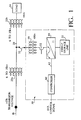
- a power compensation system 30 is shown connected in shunt with a distribution line 20 of a utility power network.
- Distribution line 20 is connected to a transmission line 18 on a transmission line network through a first transformer 22a, which steps-down a relatively high voltage (e. g., greater than 24.9 kV carried on transmission line 18) to a lower voltage, here 6kV.
- a second transformer 22b steps-down the 6kV voltage to a voltage suitable for a load 24, here 480 V.
- Power compensation system 30 includes an energy storage unit 32, an inverter system 44, and a controller 60.
- Energy storage unit 32 may be a part of a D-SMES (Distributed SMES) module which, together with inverter system 44, is capable of delivering both real and reactive power, separately or in combination, to distribution line 20.
- the DSMES module is sized at 3.0 MVA and is capable of delivering an average of 2 MWatts for periods as long as 400 milliseconds, 7.5 MVA for a full second, and 3.0 MVAR of reactive power for an indefinite period of time.
- inverter 44 under the intelligent control of controller 60, transfers reactive power to and from the utility power network.
- inverter 44 converts DC voltage from energy storage unit 32 to AC voltage and, in this embodiment, includes four inverter units 46.
- Inverter 44 can act as a source for leading and lagging reactive power.
- inverter 44 can only source real power from energy storage unit 32 for as long as real power is available.
- inverter 44 can source reactive power indefinitely assuming it is operating at its nominally rated capacity.
- inverter 44 can provide reactive power without utilizing power from energy storage unit 32.
- One example of an inverter that may be used in conjunction with the processes described herein may be obtained from Integrated Electronics, a division of American Superconductor Corp. (Part No. A0016701CH). However, the invention is not limited to use with this type of inverter and any other type of inverter may instead be used.
- Each of the four inverter units 46 is capable of providing 750 KVA continuously and 1.876 MVA in overload mode for one second.
- the outputs of each inverter unit 46 are combined on the medium-voltage side of the power transformers to yield system ratings in accordance with the following table.
- Each inverter unit 46 includes three parallel inverter modules (not shown). Because inverter units 46 are modular in form, a degree of versatility is provided to accommodate other system ratings with standard, field-proven inverter modules. A level of fault tolerance is also possible with this modular approach, although system capability may be reduced.
- Each inverter module 46 is equipped with a local slave controller (not shown) that manages local functions, such as device protection, current regulation, thermal protection, power balance among modules, and diagnostics, among others.
- the inverter units and modules are mounted in racks with integral power distribution and cooling systems.
- Inverter 44 is coupled to distribution line 20 through one or more step-down power transformers 50 and one or more switchgear units 52 (see also Fig. 1).
- Each power transformer 50 is a 24.9 kV/480 V three-phase oil-filled pad mount transformer having a nominal impedance of 5.75% on its own base rating. The power transformers are mounted outdoors adjacent to the system enclosure with power cabling protected within an enclosed conduit (not shown). As is shown in Fig. 1, a fuse 53 is connected between step-down power transformer 50 and distribution line 20.
- each switchgear unit 52 provides over-current protection between power transformers 50 and inverter units 46.
- Each of the four main inverter outputs feeds a circuit breaker rated at 480 V, 900 A RMS continuous per phase with 45 kA interruption capacity.
- Switchgear units 52 also serve as the primary disconnect means for safety and maintenance purposes.
- the switchgear units are generally mounted adjacent to the inverter unit enclosures.
- system controller 60 is a multiprocessor-driven system, which utilizes adaptive control processes.
- System controller 60 operates as a multi-state machine for processing inputs from distribution line 20 via line 42 and inverter units 46 of inverter system 44.
- System controller 60 dynamically determines the phase and magnitude of inverter units 46 as well as the real power output of D-SMES module 30.
- System controller 60 in operation, passes real-time voltage and current waveform data to the data acquisition system for processing and transmission to monitoring sites.
- System controller 60 also supports local user interfaces and safety interlocks. Controller 60 necessarily has a response time sufficient to ensure that the transfer of power to or from energy storage unit 32 occurs at a speed to address a fault or contingency on the utility system.
- controller 60 and inverter 44 are described in conjunction with an exemplary contingency occurring on the utility power network.
- the nominal voltage of the utility power network is monitored. For example, the nominal voltage on distribution line 20 is sensed either directly or from a remote device.
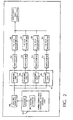
- a request is made to operate inverter 44 in overload mode (200) and, in response, controller 60 transmits a trigger signal to cause inverter 44 to increase its output current above its steady-state rating (202).
- This steady-state rating is referred to in the figures as InvtrIRefMax/I max .
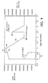
- inverter system 44 is activated to provide capacitive reactive power and real power from energy storage unit 32.
- the energy storage unit delivers 3 MWatts of real power and about 6.8 MV ARs of capacitive reactive power.
- the real power is decreased in a period 70, here the decrease is linear, to about 2 MWatts as the magnet discharges.
- period 70 e.g., 600 milliseconds
- the capacitive reactive power is increased from 6.8 MVARs to about 7.2 MVARs.
- controller 60 provides a signal to inverter 44 to stop delivery of real power.
- the cut-off current level of the energy storage unit 32 represents a power level of the energy storage unit that should be maintained for reasons relating to the reliability of the energy storage unit. That is, the energy storage unit 32 is generally not allowed to drop below this cut-off current level.
- capacitive reactive power is increased to comprise the entire maximum overload value for a period 74 (e.g., 400 milliseconds).
- the thermal heat capacity of inverter 44 is shown as a function of time.
- the inverter's ability to dissipate energy is referred to in the figures as InvtrCapacityLimit, which, if exceeded, will lead to destruction of the inverter.
- controller 60 controls inverter 44 to begin decreasing its output current, since the inverter has reached its maximum thermal heat capacity.
- controller 60 upon increasing the output current level of inverter 44, controller 60 begins to compute the accumulation of energy being dissipated in inverter 44 (204). This calculation is performed once every line cycle. To calculate the accumulation of energy dissipation (i.e., power dissipation per unit time) in the inverter, it is recognized that dominant loss mechanisms are proportional to I 2 (inverter current squared). To obtain the accumulated energy, the power being dissipated over time is integrated over all samples.
- This expression represents the accumulated thermal energy of the inverter, a static variable that is updated every AC line cycle. Calculation of the accumulation of energy continues, as shown by the dotted line of Fig. 3.
- the capacitive reactive power is decreased in ramp-like fashion -- here, linearly -- to a steady-state value (e.g., 3 MVARs).
- the capacitive reactive power is decreased in this manner to avoid an abrupt, step-like change in the reactive power transfer to the utility power network.
- a step-like abrupt change in the inverter current from, for example, 2.5 times the steady-state maximum to the steady-state maximum, can generate undesirable transients (e.g., ringing oscillations) on the utility power network, which can cause false switching and possible damage to equipment on the utility power network.
- the current is steadily decreased in accordance with the ramp-like profile (210).
- the ramp-down process is initiated at a time that ensures that when the inverter current reaches the steady-state maximum value (InvtrIRefMax), the thermal capacity limit of the inverter is exhausted. Selecting the ramp-down profile in this manner provides maximum power delivery to the load and reduces the probability of line voltage collapse, while also guarding against initiating undesirable transients on the network.
- the ramp-down profile is typically a function of the characteristic impedance of the utility network to which it is connected.
- the characteristic impedance of a network changes unpredictably over time.
- a suitable characteristic impedance value of the network can be derived from knowledge of the types of loads, conductors, reactive devices and transformers connected to the network.
- the characteristic impedance of the network can be determined by periodically applying a stimulus (e.g., a step function load) to the network and measuring the response of the network.
- a stimulus e.g., a step function load
- inverter 44 can be used to apply the step function load, while controller 60 measures the response.
- the step function load would be of sufficiently low magnitude to prevent stimulation of undesirable oscillations.
- the characteristic impedance is then used to determine the ramp-down profile.
- parabolic curve 100 represents the I 2 value of inverter 44. as a function of time.
- the area under parabolic curve 100 bounded by points abcga represents the energy dissipated as the inverter current ramps from the value of I to zero along ramp profile 102.
- the area bounded by points abega represents the energy dissipated as the inverter current decreases from the value of I to I max .
- the area bounded by points gecg is first obtained by recognizing that this area is exactly 1/3 the area of rectangle bounded by the points gecfg.
- the area bounded by the points abega is then obtained by subtracting the area bounded by points gecg from the area bounded by the points abcga.
- the foregoing expression represents the thermal capacity predictor for determining when the inverter must begin or continue the ramp-down of overcurrent toward the maximum steady-state value.
- the slope of the thermal energy content (heat content) of the inverter gradually declines during the ramp-down period in which the capacitive reactance from inverter 44 is reduced, and the slope becomes negative only after the inverter current reaches its maximum steady-state rating.
- Region 74 refers to that part that has actually accumulated
- region 82 represents the estimated accumulation that will occur from the current sample until the inverter current reaches the steady-state level. Samples are accumulated once per cycle for both regions 74 and 82, although the accumulation in region 82 is for estimation purposes.
- inverter 44 generally cannot dissipate its heat at the same rate that the power delivered to the utility network is reduced.
- controller 60 must have sufficient intelligence to recognize that, in the event of a subsequent contingency, the thermal energy content of the inverter may not have decreased back to a level corresponding to the steady-state current level.
- controller 60 begins the process by selecting (214) an incrementally higher value of estimated inverter current than the level of InvtrIRefMax (the maximum steady-state value) and using this value as if it were the actual inverter current.
- controller 60 can verify whether the estimated current can be successfully reduced to InvtrIRefMax quickly enough so as not to exceed the thermal capacity limit of the inverter (in the event that a subsequent request for an over-current is required). In particular, controller 60 determines whether the inverter thermal capacity limit will be exceeded if the ramp-down process were to be initiated at the incrementally-larger estimated current level previously mentioned. If it is not exceeded, a constant value is subtracted from the accumulation of heat energy (216) and the value of the current is incremented by the value depicting the slope of the ramp-down process, called AmpsPerCycle. The estimate is again performed at the next sample period.
- the constant value represents the inverter's thermal recovery increment a value that essentially gauges the state of recovery of the inverter from the overload. If the estimated current results in a prediction that exceeds the inverter's heat capacity limit, the thermal recovery increment is still decremented by the constant value, provided that the inverter current is actually at or below InvtrIRefMax, but the inverter current estimate remains unchanged, as it is used to constrain the peak current if a new overload current is requested. The process continues and, eventually, the full overload thermal capability of the inverter is restored and the overload current reaches its limit ofN times the steady-state rating.
- controller 60 controls inverter 44 to provide a maximum amount of inverter current should another contingency occur. Controller 60 does so without exceeding the capability the inverter and by providing a ramping-down to the steady state InvtrIRefMax level. while ensuring that the thermal capacity of the inverter is not exceeded by the time that the current declines to the InwrIRefMax level.
- a second follow-on contingency may occur while the thermal capacity is still elevated.
- the inverter current cannot be increased to the previous 750 MVAR level because the preestablished slope of the ramp down would result in the thermal capacity of the inverter being exceeded before reaching InvtrIRefMax.
- the inverter current is limited to, in this example, approximately 600 MVARs (point 86). At this peak inverter current, the inverter current can still decrease at the ramp down rate to InvtrIRefMax without, as shown in Fig. 5, exceeding the thermal limit of the inverter.
Landscapes
- Engineering & Computer Science (AREA)
- Power Engineering (AREA)
- Inverter Devices (AREA)
- Supply And Distribution Of Alternating Current (AREA)
- Control Of Electrical Variables (AREA)
- Emergency Protection Circuit Devices (AREA)
- Heat-Pump Type And Storage Water Heaters (AREA)
- Dc-Dc Converters (AREA)
- Oscillators With Electromechanical Resonators (AREA)
Applications Claiming Priority (2)
| Application Number | Priority Date | Filing Date | Title |
|---|---|---|---|
| US16737799P | 1999-11-24 | 1999-11-24 | |
| EP00979222A EP1236261B1 (de) | 1999-11-24 | 2000-11-22 | Spannungsregelung eines stromnetzes |
Related Parent Applications (2)
| Application Number | Title | Priority Date | Filing Date |
|---|---|---|---|
| EP00979222A Division EP1236261B1 (de) | 1999-11-24 | 2000-11-22 | Spannungsregelung eines stromnetzes |
| EP00979222.7 Division | 2000-11-22 |
Publications (2)
| Publication Number | Publication Date |
|---|---|
| EP1701425A2 true EP1701425A2 (de) | 2006-09-13 |
| EP1701425A3 EP1701425A3 (de) | 2011-01-05 |
Family
ID=22607129
Family Applications (2)
| Application Number | Title | Priority Date | Filing Date |
|---|---|---|---|
| EP00979222A Expired - Lifetime EP1236261B1 (de) | 1999-11-24 | 2000-11-22 | Spannungsregelung eines stromnetzes |
| EP06075796A Withdrawn EP1701425A3 (de) | 1999-11-24 | 2000-11-22 | Spannungsregelung eines Stromnetzes |
Family Applications Before (1)
| Application Number | Title | Priority Date | Filing Date |
|---|---|---|---|
| EP00979222A Expired - Lifetime EP1236261B1 (de) | 1999-11-24 | 2000-11-22 | Spannungsregelung eines stromnetzes |
Country Status (9)
| Country | Link |
|---|---|
| US (3) | US20020075701A1 (de) |
| EP (2) | EP1236261B1 (de) |
| AT (1) | ATE341848T1 (de) |
| AU (1) | AU1662401A (de) |
| CA (2) | CA2392409C (de) |
| DE (1) | DE60031158T2 (de) |
| ES (1) | ES2276704T3 (de) |
| MX (1) | MXPA02005243A (de) |
| WO (1) | WO2001039349A1 (de) |
Cited By (2)
| Publication number | Priority date | Publication date | Assignee | Title |
|---|---|---|---|---|
| ITMI20130550A1 (it) * | 2013-04-09 | 2014-10-10 | Nicolas Tringali | Dispositivo per l'erogazione supplementare di energia. |
| RU2561915C1 (ru) * | 2014-05-05 | 2015-09-10 | Федеральное государственное бюджетное образовательное учреждение высшего профессионального образования "Новосибирский государственный технический университет" | Способ регулирования напряжения узла электрической сети и узлов, примыкающих к нему |
Families Citing this family (42)
| Publication number | Priority date | Publication date | Assignee | Title |
|---|---|---|---|---|
| WO2000048286A1 (en) * | 1999-01-29 | 2000-08-17 | American Superconductor Corporation | Electric utility system with superconducting magnetic energy storage |
| US6906434B1 (en) * | 1999-01-29 | 2005-06-14 | American Superconductor Corporation | Electric utility system with superconducting magnetic energy storage |
| US6600973B1 (en) * | 1999-11-24 | 2003-07-29 | American Supercondutor Corporation | Method and apparatus for providing power to a utility network |
| WO2005027301A1 (en) * | 2003-09-16 | 2005-03-24 | General Electric Company | Method for operating a frequency converter of a generator |
| SE526001C2 (sv) * | 2003-09-26 | 2005-06-14 | Abb Research Ltd | System för överföring av elektrisk kraft |
| SE0303574D0 (sv) * | 2003-12-23 | 2003-12-23 | Abb Research Ltd | Elictric power network |
| US7091703B2 (en) * | 2004-03-04 | 2006-08-15 | American Superconductor Corporation | Dynamic reactive compensation system and method |
| WO2006000050A1 (en) * | 2004-06-25 | 2006-01-05 | Aristocrat Technologies Australia Pty Ltd | Gaming machine screen partitioning |
| US7321834B2 (en) * | 2005-07-15 | 2008-01-22 | Chang Gung University | Method for calculating power flow solution of a power transmission network that includes interline power flow controller (IPFC) |
| US7642666B2 (en) * | 2006-11-02 | 2010-01-05 | Hitachi, Ltd. | Wind power generation apparatus, wind power generation system and power system control apparatus |
| US7813884B2 (en) * | 2008-01-14 | 2010-10-12 | Chang Gung University | Method of calculating power flow solution of a power grid that includes generalized power flow controllers |
| ES2378616T3 (es) * | 2008-04-18 | 2012-04-16 | Abb Research Ltd. | Aparato y procedimiento para el control de una línea de transmisión |
| US7940029B2 (en) * | 2008-07-02 | 2011-05-10 | American Superconductor Corporation | Static VAR corrector |
| US7941227B2 (en) * | 2008-09-03 | 2011-05-10 | Boston Scientific Neuromodulation Corporation | Implantable electric stimulation system and methods of making and using |
| US8838285B2 (en) | 2011-07-26 | 2014-09-16 | General Electric Company | Devices and methods for decentralized power factor control |
| US8761954B2 (en) | 2011-07-26 | 2014-06-24 | General Electric Company | Devices and methods for decentralized coordinated volt/VAR control |
| US8838284B2 (en) | 2011-07-26 | 2014-09-16 | General Electric Company | Devices and methods for decentralized Volt/VAR control |
| US8965588B2 (en) | 2011-07-26 | 2015-02-24 | General Electric Company | Devices and methods for decentralized voltage control |
| US9570909B2 (en) | 2011-07-26 | 2017-02-14 | General Electric Company | Devices and methods for decentralized power loss reduction control |
| US8811038B2 (en) | 2011-11-11 | 2014-08-19 | Gridco, Inc. | Apparatus and method for soft switching in a medium voltage to low voltage converter |
| JP5917132B2 (ja) * | 2011-12-22 | 2016-05-11 | 株式会社東芝 | 電気機器の運転制御システム及び方法 |
| US9229036B2 (en) | 2012-01-03 | 2016-01-05 | Sentient Energy, Inc. | Energy harvest split core design elements for ease of installation, high performance, and long term reliability |
| US9182429B2 (en) | 2012-01-04 | 2015-11-10 | Sentient Energy, Inc. | Distribution line clamp force using DC bias on coil |
| US9373958B2 (en) | 2012-03-22 | 2016-06-21 | Sunpower Corporation | Control techniques for photovoltaic power plants |
| US9240682B2 (en) * | 2012-09-18 | 2016-01-19 | Sunpower Corporation | Mitigation of arc flash hazard in photovoltaic power plants |
| US9685887B2 (en) * | 2012-10-12 | 2017-06-20 | Younicos Inc. | Controlling power conversion systems |
| US10014681B2 (en) | 2013-12-03 | 2018-07-03 | International Business Machines Corporation | Providing electricity to essential equipment during an emergency |
| CN104362652B (zh) * | 2014-12-05 | 2016-05-04 | 广东电网有限责任公司电力科学研究院 | 发电机励磁调差系数的控制方法和装置 |
| US9954354B2 (en) | 2015-01-06 | 2018-04-24 | Sentient Energy, Inc. | Methods and apparatus for mitigation of damage of power line assets from traveling electrical arcs |
| EP3118961B1 (de) * | 2015-07-17 | 2019-06-05 | "Condensator Dominit" Dr. Christian Dresel Gesellschaft für Leistungselektronik, Energietechnik und Netzqualität mbH | Nutzung elektrischer netz-verzerrungsenergie mittels gleichrichter |
| US9984818B2 (en) | 2015-12-04 | 2018-05-29 | Sentient Energy, Inc. | Current harvesting transformer with protection from high currents |
| KR101837649B1 (ko) * | 2015-12-30 | 2018-03-12 | 주식회사 효성 | 무효전력 보상제어기용 차단기 제어장치 및 제어방법 |
| DE102016116207A1 (de) * | 2016-08-31 | 2018-03-01 | Sma Solar Technology Ag | Energieversorgungsanlage sowie Verfahren und Regelvorrichtung zur Regelung einer Energieversorgungsanlage |
| US10634733B2 (en) | 2016-11-18 | 2020-04-28 | Sentient Energy, Inc. | Overhead power line sensor |
| JP6945315B2 (ja) * | 2017-03-24 | 2021-10-06 | 三菱重工業株式会社 | 発電プラント及び発電プラントの運転方法 |
| WO2019120397A1 (en) | 2017-12-20 | 2019-06-27 | Vestas Wind Systems A/S | Adaptive active power control in renewable energy power plants |
| US10734821B2 (en) | 2018-03-08 | 2020-08-04 | Saudi Arabian Oil Company | Power control system |
| US11041915B2 (en) | 2018-09-18 | 2021-06-22 | Sentient Technology Holdings, LLC | Disturbance detecting current sensor |
| US11476674B2 (en) | 2018-09-18 | 2022-10-18 | Sentient Technology Holdings, LLC | Systems and methods to maximize power from multiple power line energy harvesting devices |
| US12050241B2 (en) | 2018-10-15 | 2024-07-30 | Sentient Technology Holdings, Llc. | Power line sensors with automatic phase identification |
| US11125832B2 (en) | 2018-12-13 | 2021-09-21 | Sentient Technology Holdings, LLC | Multi-phase simulation environment |
| US11609590B2 (en) | 2019-02-04 | 2023-03-21 | Sentient Technology Holdings, LLC | Power supply for electric utility underground equipment |
Citations (1)
| Publication number | Priority date | Publication date | Assignee | Title |
|---|---|---|---|---|
| US3217171A (en) | 1961-05-15 | 1965-11-09 | Gen Electric | Variable frequency oscillator |
Family Cites Families (35)
| Publication number | Priority date | Publication date | Assignee | Title |
|---|---|---|---|---|
| FR2266347B1 (de) * | 1974-03-27 | 1982-07-02 | Siemens Ag | |
| US4013937A (en) * | 1974-07-22 | 1977-03-22 | Westinghouse Electric Corporation | Naturally commutated cycloconverter with controlled input displacement power factor |
| JPS5867302A (ja) | 1981-10-19 | 1983-04-21 | Shin Etsu Polymer Co Ltd | ガス交換膜 |
| JPS5921870A (ja) | 1982-07-26 | 1984-02-03 | 三菱重工業株式会社 | 円筒タンクの屋根扛上装置 |
| JPS5952809A (ja) | 1982-09-20 | 1984-03-27 | Hitachi Ltd | 電磁コイル保護装置 |
| JPS61114509A (ja) | 1984-11-09 | 1986-06-02 | Toshiba Corp | 超電導コイル装置 |
| JPS6419929A (en) | 1987-07-15 | 1989-01-24 | Hitachi Ltd | Solar power generator |
| US4962354A (en) | 1989-07-25 | 1990-10-09 | Superconductivity, Inc. | Superconductive voltage stabilizer |
| US5134356A (en) * | 1990-06-22 | 1992-07-28 | Board Of Regents Of The University Of Washington | Reactive power compensator |
| JP2760646B2 (ja) * | 1990-09-18 | 1998-06-04 | 株式会社東芝 | 電力変換装置の電流指令値演算装置 |
| CA2041272C (en) * | 1991-04-25 | 1999-12-07 | Philip Chadwick | Phase controlled capacitor for series compensation of a high voltage transmission line |
| US5202583A (en) * | 1991-12-13 | 1993-04-13 | Electric Power Research Institute | Thyristor controlled series capacitor vernier control system |
| US5198746A (en) * | 1991-09-16 | 1993-03-30 | Westinghouse Electric Corp. | Transmission line dynamic impedance compensation system |
| US5424627A (en) * | 1991-12-13 | 1995-06-13 | Electric Power Research Institute | Modular thyristor controlled series capacitor control system |
| US5621305A (en) * | 1991-12-13 | 1997-04-15 | Electric Power Research Institute, Inc. | Overload management system |
| US5343139A (en) * | 1992-01-31 | 1994-08-30 | Westinghouse Electric Corporation | Generalized fast, power flow controller |
| JPH05268727A (ja) | 1992-03-19 | 1993-10-15 | Toshiba Corp | エネルギ変換装置 |
| ATE162343T1 (de) * | 1992-05-18 | 1998-01-15 | Siemens Ag | Verfahren und vorrichtung zur erzeugung eines synchronisiersignals für einen steuersatz zur ansteuerung eines stromrichterventils eines gesteuerten serienkompensators |
| ATE128284T1 (de) * | 1992-05-20 | 1995-10-15 | Siemens Ag | Verfahren und vorrichtung zur erkennung von defekten in einem ansteuersystem eines gesteuerten serienkompensators. |
| US5422561A (en) * | 1992-11-23 | 1995-06-06 | Southern California Edison Company | Automated voltage and VAR control in power transmission and distribution networks |
| US5519312A (en) | 1993-11-29 | 1996-05-21 | Alfred University | Hybrid system of fuel cell and superconducting magnetic energy storage device |
| DK0792483T3 (da) * | 1994-07-22 | 2001-08-20 | Electric Power Res Inst | Transmissionsledningseffektregulator med en kontinuerligt styrbart spændingskilde, der reagerer på et aktivt effektbehov og et reaktivt effektbehov |
| US5642007A (en) * | 1994-12-30 | 1997-06-24 | Westinghouse Electric Corporation | Series compensator inserting real and reactive impedance into electric power system for damping power oscillations |
| US5610501A (en) * | 1995-02-01 | 1997-03-11 | Westinghouse Electric Corporation | Dynamic power and voltage regulator for an ac transmission line |
| US5644218A (en) | 1995-02-01 | 1997-07-01 | Superconductivity, Inc. | Protection device for a superconducting coil of a superconducting voltage stabilizer |
| US5952816A (en) * | 1995-04-21 | 1999-09-14 | General Electric Co. | Compensation for power transfer systems using variable rotary transformer |
| US5670864A (en) * | 1995-05-26 | 1997-09-23 | Pacific Scientific Company | Adaptive automatic power capacitor for controlling controller a capacitor bank of a power distribution system |
| US5814975A (en) * | 1995-06-05 | 1998-09-29 | Westinghouse Electric Corporation | Inverter controlled series compensator |
| US5694308A (en) * | 1995-07-03 | 1997-12-02 | Motorola, Inc. | Method and apparatus for regulated low voltage charge pump |
| US5698969A (en) * | 1995-11-29 | 1997-12-16 | Westinghouse Electric Corporation | Apparatus and method for interline power flow control |
| US5808452A (en) * | 1997-09-15 | 1998-09-15 | Gyugyi; Laszlo | Power flow controller with dc-to-dc converter linking shunt and series connected inverters |
| JP3450690B2 (ja) * | 1998-01-20 | 2003-09-29 | 三菱電機株式会社 | 電力系統の補償制御装置 |
| CA2268566C (en) * | 1998-04-10 | 2001-10-02 | Kabushiki Kaisha Toshiba | Ac transmission system with reactance compensation |
| US6445555B1 (en) | 1999-11-24 | 2002-09-03 | American Superconductor Corporation | Method and apparatus for discharging a superconducting magnet |
| US6900619B2 (en) * | 1999-11-24 | 2005-05-31 | American Superconductor Corporation | Reactive power compensation to minimize step voltage changes and transients |
-
2000
- 2000-11-22 AT AT00979222T patent/ATE341848T1/de not_active IP Right Cessation
- 2000-11-22 AU AU16624/01A patent/AU1662401A/en not_active Abandoned
- 2000-11-22 MX MXPA02005243A patent/MXPA02005243A/es active IP Right Grant
- 2000-11-22 ES ES00979222T patent/ES2276704T3/es not_active Expired - Lifetime
- 2000-11-22 WO PCT/US2000/032182 patent/WO2001039349A1/en not_active Ceased
- 2000-11-22 EP EP00979222A patent/EP1236261B1/de not_active Expired - Lifetime
- 2000-11-22 EP EP06075796A patent/EP1701425A3/de not_active Withdrawn
- 2000-11-22 DE DE60031158T patent/DE60031158T2/de not_active Expired - Lifetime
- 2000-11-22 CA CA002392409A patent/CA2392409C/en not_active Expired - Fee Related
- 2000-11-22 CA CA002676240A patent/CA2676240A1/en not_active Abandoned
-
2001
- 2001-11-14 US US10/002,847 patent/US20020075701A1/en not_active Abandoned
-
2002
- 2002-07-15 US US10/196,707 patent/US6577108B2/en not_active Ceased
-
2007
- 2007-01-19 US US11/655,817 patent/USRE41170E1/en not_active Expired - Lifetime
Patent Citations (1)
| Publication number | Priority date | Publication date | Assignee | Title |
|---|---|---|---|---|
| US3217171A (en) | 1961-05-15 | 1965-11-09 | Gen Electric | Variable frequency oscillator |
Non-Patent Citations (1)
| Title |
|---|
| A. H. M. A. RAHIM ET AL.: "Control of Subsyschronus Resonant Modes in a Series Compensated System through Superconducting Magnetic Energy Storage Units", IEEE TRANSACTIONS ON ENERGY CONVERSION, vol. 3, no. 1, 1996, pages 175 - 180 |
Cited By (2)
| Publication number | Priority date | Publication date | Assignee | Title |
|---|---|---|---|---|
| ITMI20130550A1 (it) * | 2013-04-09 | 2014-10-10 | Nicolas Tringali | Dispositivo per l'erogazione supplementare di energia. |
| RU2561915C1 (ru) * | 2014-05-05 | 2015-09-10 | Федеральное государственное бюджетное образовательное учреждение высшего профессионального образования "Новосибирский государственный технический университет" | Способ регулирования напряжения узла электрической сети и узлов, примыкающих к нему |
Also Published As
| Publication number | Publication date |
|---|---|
| CA2392409C (en) | 2009-11-17 |
| US20030026114A1 (en) | 2003-02-06 |
| AU1662401A (en) | 2001-06-04 |
| ES2276704T3 (es) | 2007-07-01 |
| EP1236261A1 (de) | 2002-09-04 |
| EP1236261B1 (de) | 2006-10-04 |
| DE60031158T2 (de) | 2007-10-25 |
| US6577108B2 (en) | 2003-06-10 |
| MXPA02005243A (es) | 2003-01-28 |
| CA2392409A1 (en) | 2001-05-31 |
| US20020075701A1 (en) | 2002-06-20 |
| CA2676240A1 (en) | 2001-05-31 |
| USRE41170E1 (en) | 2010-03-30 |
| WO2001039349A1 (en) | 2001-05-31 |
| ATE341848T1 (de) | 2006-10-15 |
| DE60031158D1 (de) | 2006-11-16 |
| EP1701425A3 (de) | 2011-01-05 |
Similar Documents
| Publication | Publication Date | Title |
|---|---|---|
| EP1236261B1 (de) | Spannungsregelung eines stromnetzes | |
| US7091703B2 (en) | Dynamic reactive compensation system and method | |
| CA2018055C (en) | Superconductive voltage stabilizer | |
| EP1236212B1 (de) | Kondensatorbankschaltung | |
| EP1855367B1 (de) | Verfahren und einrichtung zum injizieren von reaktivem strom während eines hauptversorgungsspannungseinbruchs | |
| US5621305A (en) | Overload management system | |
| EP1281225B1 (de) | Verfahren und system zur spannungs unter stützung zu einer an ein spannungnetz angeschlossene last | |
| US5804949A (en) | Thyristor-controlled series capacitor triggering system | |
| JP2009201348A (ja) | 電力伝送システム用の動的復旧型サポートシステムおよび方法 | |
| US8411400B2 (en) | Method and apparatus for mitigation of dynamic overvoltage | |
| JP3426961B2 (ja) | 自律型配電線電圧調整装置及びそれを用いた高圧配電線の電圧制御方法 | |
| CA1101932A (en) | Method and apparatus for controlling the real and reactive power behavior of a high voltage d. c. transmission (hdt) system | |
| CN216390522U (zh) | 一种配电柜 | |
| CN116154716A (zh) | 一种弧光接地快速转为金属接地的主动干预方法及设备 | |
| EP4687250A1 (de) | Unterdrückung von transientem umkehrstrom auf der gleichstromseite eines hgü-systems | |
| Arunachalam et al. | Performance verification of TCSC control and protection equipment using RTDS | |
| CN121710510A (zh) | 电源切换装置以及方法 | |
| Francois et al. | SVC protection and control basics (for Entergy's porter SVC with external capacitor bank switching) | |
| CN113783212A (zh) | 一种配电柜及其应用方法 | |
| Chen et al. | The effects of fault clearance practices on adjustable speed drives | |
| Omar et al. | Design requirements for a dynamic series compensator for voltage sags mitigation in low voltage distribution system | |
| JPH03289326A (ja) | 受電力率制御の需要家電力設備 | |
| Chitra | Solar Powered Dynamic Voltage Restorer for Fault Current Interruption | |
| Kuypers et al. | Aspects of series controlled flexible AC transmission system planning and operation | |
| JPH0126253B2 (de) |
Legal Events
| Date | Code | Title | Description |
|---|---|---|---|
| PUAI | Public reference made under article 153(3) epc to a published international application that has entered the european phase |
Free format text: ORIGINAL CODE: 0009012 |
|
| 17P | Request for examination filed |
Effective date: 20060427 |
|
| AC | Divisional application: reference to earlier application |
Ref document number: 1236261 Country of ref document: EP Kind code of ref document: P |
|
| AK | Designated contracting states |
Kind code of ref document: A2 Designated state(s): AT BE CH CY DE DK ES FI FR GB GR IE IT LI LU MC NL PT SE TR |
|
| RIN1 | Information on inventor provided before grant (corrected) |
Inventor name: HUBERT, THOMAS GREGORY Inventor name: FOLTS, DOUGLAS C. Inventor name: BUCKLES, WARREN ELLIOTT |
|
| RAP1 | Party data changed (applicant data changed or rights of an application transferred) |
Owner name: AMERICAN SUPERCONDUCTOR CORPORATION |
|
| PUAL | Search report despatched |
Free format text: ORIGINAL CODE: 0009013 |
|
| AK | Designated contracting states |
Kind code of ref document: A3 Designated state(s): AT BE CH CY DE DK ES FI FR GB GR IE IT LI LU MC NL PT SE TR |
|
| AKX | Designation fees paid |
Designated state(s): AT BE CH CY DE DK ES FI FR GB GR IE IT LI LU MC NL PT SE TR |
|
| STAA | Information on the status of an ep patent application or granted ep patent |
Free format text: STATUS: THE APPLICATION HAS BEEN WITHDRAWN |
|
| 18W | Application withdrawn |
Effective date: 20180416 |