EP1701432B1 - Elektrischer Ventilatormotor für Fahrzeuge und Verfahren für seine Montage - Google Patents
Elektrischer Ventilatormotor für Fahrzeuge und Verfahren für seine Montage Download PDFInfo
- Publication number
- EP1701432B1 EP1701432B1 EP06290349A EP06290349A EP1701432B1 EP 1701432 B1 EP1701432 B1 EP 1701432B1 EP 06290349 A EP06290349 A EP 06290349A EP 06290349 A EP06290349 A EP 06290349A EP 1701432 B1 EP1701432 B1 EP 1701432B1
- Authority
- EP
- European Patent Office
- Prior art keywords
- stator
- strap
- electronic card
- card
- electric motor
- Prior art date
- Legal status (The legal status is an assumption and is not a legal conclusion. Google has not performed a legal analysis and makes no representation as to the accuracy of the status listed.)
- Expired - Lifetime
Links
Images



Classifications
-
- H—ELECTRICITY
- H02—GENERATION; CONVERSION OR DISTRIBUTION OF ELECTRIC POWER
- H02K—DYNAMO-ELECTRIC MACHINES
- H02K5/00—Casings; Enclosures; Supports
- H02K5/04—Casings or enclosures characterised by the shape, form or construction thereof
- H02K5/22—Auxiliary parts of casings not covered by groups H02K5/06-H02K5/20, e.g. shaped to form connection boxes or terminal boxes
-
- H—ELECTRICITY
- H02—GENERATION; CONVERSION OR DISTRIBUTION OF ELECTRIC POWER
- H02K—DYNAMO-ELECTRIC MACHINES
- H02K11/00—Structural association of dynamo-electric machines with electric components or with devices for shielding, monitoring or protection
- H02K11/30—Structural association with control circuits or drive circuits
- H02K11/33—Drive circuits, e.g. power electronics
-
- H—ELECTRICITY
- H02—GENERATION; CONVERSION OR DISTRIBUTION OF ELECTRIC POWER
- H02K—DYNAMO-ELECTRIC MACHINES
- H02K7/00—Arrangements for handling mechanical energy structurally associated with dynamo-electric machines, e.g. structural association with mechanical driving motors or auxiliary dynamo-electric machines
- H02K7/14—Structural association with mechanical loads, e.g. with hand-held machine tools or fans
-
- H—ELECTRICITY
- H02—GENERATION; CONVERSION OR DISTRIBUTION OF ELECTRIC POWER
- H02K—DYNAMO-ELECTRIC MACHINES
- H02K2203/00—Specific aspects not provided for in the other groups of this subclass relating to the windings
- H02K2203/03—Machines characterised by the wiring boards, i.e. printed circuit boards or similar structures for connecting the winding terminations
Definitions
- the present invention relates to an electric motor for a motor vehicle fan, according to the preamble of claim 1.
- EP-A-1,079,502 an electric motor of the aforementioned type, wherein the stator comprises a plurality of coils for generating a rotating electromagnetic field.
- the coils are electrically connected to a control board fixed in the motor housing.
- the electrical connection means between the control card and the coils comprise tabs which have an axial portion connected to a coil, and a radial portion in the form of lyre, connected to the card.
- the radial portion is elastically deformable.
- An object of the invention is therefore to provide an electric motor for a motor vehicle whose reliability is improved.
- the subject of the invention is an electric motor according to claim 1.
- the engine according to the invention may comprise one or more of the features which are the subject of claims 2 to 5.
- the invention also relates to a mounting method according to claim 6.
- the method of the invention may comprise one or more of the features which are the subject of claims 7 to 9.
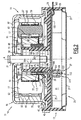
- the first electric motor 11 is a brushless electric motor, intended to be used, for example, in a motor-blower unit for a front block of a motor vehicle.
- the motor 11 comprises a support plate 13, a stator 15 mounted integral with the plate 13, the stator 15 comprising a plurality of coils 17 for generating a rotating electromagnetic field.
- the motor 11 further comprises a rotor 19 provided with a shaft 21 rotatably mounted on the support 13 about an axis AA 'supposed vertical rotor, a housing 23 for controlling the rotation of the rotor 19 comprising an electronic card 25, and means 27 for electrical connection between each coil 17 and the card 25.
- the plate 13 comprises a base 29, a central sleeve 31 which protrudes upwardly relative to the base 29, and a lower peripheral wall 33 which delimits a lower housing 35 closed by a cover 37.
- the base 29 extends substantially in a horizontal plane. It is delimited internally by the central sleeve 31. It has three openings 39 for passage of the connection means 27, located around the sleeve 31 and opening into the housing 35.
- the base 29 includes, on its upper surface 41, an inner annular rib 43 and an outer annular peripheral rim 45 which protrude upwardly.
- the central sleeve 31 is formed by a hollow cylinder. It delimits a central cavity 47 opening upwards through an upper opening 49 and opening downwards in the lower housing 35.
- the central sleeve 31 delimits on its inner surface, in the vicinity of the upper opening 49, an annular shoulder 51 bearing support. It defines on its outer surface, under the shoulder 51, an outer annular shoulder 53 for receiving the stator 15.
- the lower wall 33 projects downwards from the base 29. It extends in the lower extension of the flange 45.
- the stator 15 comprises, in addition to the coils 17, a coil holder 55 mounted on the central sleeve 31, and upper and lower insulating flanges 57 and 59 respectively applied to the upper and lower surfaces of the coil holder 55.
- the support 55 comprises a central ring 61, radial arms 63 commonly called teeth projecting radially outwardly from the central ring 61, and for each tooth 63, a terminal plate 65 extending peripherally to the end of the tooth 63.
- the central ring 61 internally delimits a central cavity 67 of axis A-A 'of complementary shape to the outer surface of the sleeve 31.
- the sleeve 31 is received in the central cavity 67.
- the ring 61 has, opposite each tooth 63, a through axial cavity 69, of substantially rectangular cross section.
- the lower flange 59 is made from an electrical insulating material. It has an upper surface 71 substantially conjugate to the lower surface 73 of the coil support 55. It also comprises fingers 75 for receiving the connecting means 21 and the upper projections 77 of electrical insulation, arranged in the intermediate notches 79 arranged between the adjacent teeth 63.
- the fingers 75 are inserted into the through cavities 69 of the central ring 61.
- Each finger 75 comprises an upper portion 81 inserted in a through cavity 69 and a lower portion 83 which projects downwardly relative to the lower surface 71. passing through passage 85 is formed in each finger 75.
- the upper flange 57 is made of an electrical insulating material. It has a shape substantially conjugate to the upper surface of the coil support 55. It further comprises lower projections 87 received in the notches 79 between the teeth 63 facing the protrusions 77, and an inner annular flange 89 which extends around the axis AA 'above the central ring 61.
- the coils 17 are wound around the teeth 63, each around a radial axis.
- the coils 17 enclose the projections 77 and 87 of the upper and lower flanges 57 and 59.
- the rotor 19 comprises an inverted cylinder head 91 integral with the rotation shaft 21, and a plurality of permanent magnets 93 fixed in this cylinder head 91.
- the yoke 91 comprises a vertical peripheral skirt 95 which extends facing the end plates 65, and an upper bottom 97 which extends opposite the ring 61.
- the rotation shaft 21 is forcibly mounted in a central collar 98 of the cylinder head 91. It projects downwardly therein from the upper bottom 97. Upper and lower bearings 99A and 99B are interposed between the rotation shaft 21 and the central sleeve 31.
- the upper bearing 99A is keyed on the upper shoulder 51 and the lower bearing 99B is received against a lower shoulder 101 formed on an outer surface of the shaft 21.
- the rotor 19 is thus rotatably mounted about the axis AA 'by to the stator 15.
- the permanent magnets 93 are glued on the inner surface of the skirt 95. They extend substantially opposite the end plates 65, with the interposition of an annular clearance.
- control box 23 is disposed in the housing 35. It comprises, in addition to the electronic card 25, son 103 of electrical connection of the electronic card 25 to a DC voltage source.
- the electronic card 25 is screwed on a lower surface 105 of the base 29. It delimits three openings 107 passing through formed substantially opposite the passage openings 39 of the base 29.
- the electronic card 25 integrated into the engine has the function of converting the DC signal delivered by the voltage source into a three-phase AC signal.
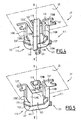
- the electrical connection means 27 comprise three phase lugs 109 mounted integral with the stator 15. They furthermore comprise, for each lug 109, a receiving jumper 111 mounted integral with the card 25, and a flexible link 113, formed by a substantially freely deformable braid, which connects the jumper 111 to the tab 109.
- a single leg 109 is shown on the Figure 2 .
- Each tab 109 comprises an upper part 115 for fixing to the stator, at least one hook 117 for electrical connection to the coils 17, and a lower part 119 for connection to the electronic card 25.
- the upper attachment portion 115 is force-fitted into the through passage 85 of a finger 75.
- Each hook 117 protrudes radially outwardly and downwardly from a medial portion of the tab 109. Each hook 117 extends in the space defined between the base 29 and the support 55, facing the windings 17. Each hook 117 is connected to at least one coil 17 by connection wires 118.
- the lower portion 119 of the tab 109 projects into the lower housing 35 through the passage openings 39 and 107 formed respectively in the base 29 and in the card 25. It defines a central notch 121 of axis BB 'parallel to the 'axis AA' which opens at its lower end. As illustrated by Figure 4 the notch 121 emerges laterally into the lateral surfaces 123B and 123C of the tab 109.
- Each jumper 111 comprises an axial profile 125 and upper transverse tabs 127 for attachment to the electronic card 25, pressed against the card 25.
- the jumper 111 is made of an electrically conductive material. Each jumper 111 is electrically connected to one of the three phases generated by the electronic card 25.
- the axial profile 125 has a U-shaped cross section formed by three vertical plane walls 129.
- the walls 129 of the profile surround the opening 107.
- the two opposite vertical walls 129B and 129C of the profile 125 extend respectively facing the surfaces.
- the height of the side walls 123, taken along the axis BB ' is less than the height of the lower portion 119 of the tab.
- Each wall 129B, 129C comprises, on its lower edge, a fork 131 forming a positioning guide of the braid 113, projecting outwards.
- the lower edge 137 of the guides 131 extends substantially facing the bottom 138 of the notch 121 when the stator 15 is mounted on the plate 13.
- the tabs 127 are integral with the profile 125. They extend transversely from the upper edge of the walls 129.
- the braid 113 is formed from deformable metal wires conducting electricity.
- the braid 113 is substantially freely deformable, that is to say that it is substantially without shape memory. It comprises two end regions 139B and 139C respectively fixed on the respective outer surfaces of the side walls 129B and 129C and engaged in the guides 131.
- the braid 113 also comprises a substantially freely deformable intermediate region 141 extending under the jumper 111 between end regions 139B and 139C. The braid 113 thus rides the rider 111.
- the intermediate region 141 of the braid is engaged in the central notch 121 of the tab 109.
- the lower portion 119 of the tab 109 is crimped on the intermediate region 141.
- the electronic card 25 When the electronic card 25 is electrically powered by the wires 103, it selectively controls the power supply of the different connection tabs 109 to create an electromagnetic field rotating opposite the permanent magnets 93 of the rotor.
- the power supply power is transmitted to the coils 17 via successively the jumper 111, the braid 113, the tab 109, the hook 117 and the son 118.
- the magnets 93 Under the effect of this rotating electromagnetic field, the magnets 93 generate a driving force of the rotor 19 in rotation about the axis A-A '.
- the intermediate region 141 of the braid being substantially freely deformable, the vibrations are absorbed by this intermediate region 141 and are not transmitted to the electronic card 25.
- the electronic card 25 is not subjected to vibrations of high intensity from the stator 15, which improves its life and increases the reliability of the engine 11.
- the electronic card 25 is screwed on the lower surface 105 of the base 29, and the jumpers 111 are fixed on the electronic card 25. Then, the end regions 139B and 139C of the braid are arranged in the 131 and are welded to the respective vertical walls 129B and 129C of the jumper 111.
- the upper and lower flanges 57 and 59 are applied to the coil support 55.
- the coils 17 are then wound around the teeth 63, and the connecting tabs 109 are forced into the through-passages 85.
- connecting wires 118 are connected between the coils 17 and the hooks 117.
- the coil support 55 is then mounted on the central sleeve 31. During this assembly, the lower portions 119 of the tabs 109 are introduced into the respective through openings 39 and 107 of the base 29 and the electronic card 25.
- each lug 109 then enters an associated jumper 111.
- the braid 113 fits easily into the notch 121, since the precise positioning of the intermediate region 141 relative to the tab 109 is provided by the guides 131 which receive the end regions 139 of the braid 113.
- the lower part 119 of the lug 109 is then crimped onto the braid 113.
- the tab 109 is devoid of indentation, and the rider 111 is devoid of guides 131.
- the braid 113 is positioned in the jumper 111 by means of vertical guide slots 143 formed in the opposite side walls 129B and 129C of the jumper.
- the slots 143 open into the respective lower edges of the walls 129B and 129C and extend facing one another.
- the lower portion 119 of the connecting tab 109 pushes the free end region 139B of the braid downward away from the positioning slot 143C.
- the free end region 139B then plates against the lateral surface 123B of the lug 109 facing the wall 129B, which facilitates its attachment by welding against the lower portion 119 of the lug 109.
- the operation of the second motor according to the invention is moreover analogous to the operation of the first motor 11 according to the invention.
Landscapes
- Engineering & Computer Science (AREA)
- Power Engineering (AREA)
- Microelectronics & Electronic Packaging (AREA)
- Insulation, Fastening Of Motor, Generator Windings (AREA)
- Motor Or Generator Frames (AREA)
- Manufacture Of Motors, Generators (AREA)
Claims (9)
- Elektromotor (11) für einen Kraftfahrzeuglüfter, des Typs, der aufweist:- einen Stator (15), der mindestens eine Einrichtung (17) zum Erzeugen eines elektromagnetischen Drehfeldes aufweist,- einen Rotor (19), der relativ zu dem Stator (15) um eine Rotorachse (A-A') drehbar montiert ist,- ein Gehäuse (23) zum Steuern der Rotation des Rotors (19), das einstückig mit dem Stator (15) montiert ist, wobei das Gehäuse (23) mindestens eine elektronische Karte (25) zum Steuern der Rotation des Rotors (19) und Mittel (27) zum elektrischen Anschließen der elektronischen Karte (25) und der oder jeder Erzeugungseinrichtung (17) enthält,wobei die Anschlussmittel (27) im Wesentlichen frei verformbar sind,
und wobei die Anschlussmittel (27) ein im Wesentlichen frei verformbares Verbindungsstück (113) aus elektrisch leitendem Material aufweisen, das einen mit der elektronischen Karte (25) einstückigen Bereich (141, 139C) und einen mit dem Stator (15) einstückigen Bereich (139B, 139C) aufweist,
dadurch gekennzeichnet, dass das Verbindungsstück durch eine im Wesentlichen frei verformbare Litze ausgebildet ist. - Elektromotor (11) gemäß Anspruch 1, dadurch gekennzeichnet, dass die Anschlussmittel (27) Führungen (131, 143) zum Positionieren des Verbindungsstücks (113) aufweisen, die mit einer/einem von der Karte (25) oder dem Stator (15) einstückig sind, wobei mindestens ein Ende (139B) des Verbindungsstücks (113) an einer der Positionierungsführungen (131) befestigt ist.
- Elektromotor (11) gemäß Anspruch 2, dadurch gekennzeichnet, dass zwei Enden (139B, 139C) des Verbindungsstücks (113) an einer der Positionierungsführungen (131) befestigt sind, wobei das Verbindungsstück (113) einen dazwischenliegenden Bereich (141) aufweist, der im Wesentlichen frei verformbar ist und sich zwischen den Enden (139B, 139C) erstreckt, und an dem die/der andere von der Karte (25) oder dem Stator (15) befestigt ist.
- Elektromotor (11) gemäß einem der Ansprüche 2 bis 3, dadurch gekennzeichnet, dass die Positionierungsführungen in einer Klammer (111) enthalten sind, die vorspringend auf der elektronischen Karte (25) montiert ist, wobei der Stator (15) eine Lasche (109) zum elektrischen Anschließen aufweist, die gegenüber der Klammer (111) positioniert ist.
- Elektromotor (11) gemäß Anspruch 4, dadurch gekennzeichnet, dass die Klammer ein Axialprofil (125), das einen Querschnitt in U-Form aufweist, und Befestigungszungen (127) zum Befestigen an der elektronischen Karte (25) aufweist, die gegen die Karte (25) gepresst sind.
- Verfahren zu Montieren eines Motors (11) gemäß einem der Ansprüche 1 bis 5, dadurch gekennzeichnet, dass es die folgenden Schritte aufweist:(a) Positionieren eines ersten Anschlussteils (119), der einstückig mit dem Stator (115) ist, benachbart zu einem zweiten Anschlussteil (111), der einstückig mit der elektronischen Karte (25) ist, und(b) Befestigen eines im Wesentlichen frei verformbaren Verbindungsstücks (113) aus elektrisch leitendem Material, das von einer im Wesentlichen frei verformbaren Litze gebildet wird, an dem einen und an dem anderen der Anschlussteile (111, 119).
- Montierverfahren gemäß Anspruch 6, dadurch gekennzeichnet, dass es die folgenden Schritte aufweist:- vor dem Schritt (a) Befestigen mindestens eines Endes (139B) des Verbindungsstücks (113) in Positionierungsführungen, die mit einem/einer von dem Stator (15) und der elektronischen Karte (25) einstückig sind, und- während des Schrittes (a) Bringen des Anschlussteils (119) des/der anderen von dem Stator (15) und der elektronischen Karte (25) in Kontakt mit dem Verbindungsstück (113).
- Montierverfahren gemäß Anspruch 7, dadurch gekennzeichnet, dass vor dem Schritt (a) zwei Enden (139B, 139C) des Verbindungsstücks (113) in den Positionierungsführungen befestigt werden, und dass während des Schrittes (a) der Anschlussbereich (119) des/der anderen von dem Stator (15) und der elektronischen Karte (15) in Kontakt mit einem Zwischenbereich (141) des Verbindungstücks (113) gebracht wird, der zwischen den beiden Enden (139B, 139C) positioniert ist.
- Montierverfahren gemäß Anspruch 7, dadurch gekennzeichnet, dass während des Schrittes (a) durch Zusammenwirken des Anschlussteils (119) und des Verbindungsstücks (113) ein freies Ende (139C) des Verbindungsstücks (113) zwischen einer Ruhestellung in Eingriff mit den Positionierungsführungen und einer aktiven Befestigungsposition gestützt auf den einen (119) der Anschlussteile bewegt wird.
Applications Claiming Priority (1)
| Application Number | Priority Date | Filing Date | Title |
|---|---|---|---|
| FR0502268A FR2882867B1 (fr) | 2005-03-07 | 2005-03-07 | Moteur electrique pour ventilateur de vehicule automobile, et procede de montage associe |
Publications (2)
| Publication Number | Publication Date |
|---|---|
| EP1701432A1 EP1701432A1 (de) | 2006-09-13 |
| EP1701432B1 true EP1701432B1 (de) | 2009-12-16 |
Family
ID=35229723
Family Applications (1)
| Application Number | Title | Priority Date | Filing Date |
|---|---|---|---|
| EP06290349A Expired - Lifetime EP1701432B1 (de) | 2005-03-07 | 2006-03-01 | Elektrischer Ventilatormotor für Fahrzeuge und Verfahren für seine Montage |
Country Status (4)
| Country | Link |
|---|---|
| EP (1) | EP1701432B1 (de) |
| DE (1) | DE602006011068D1 (de) |
| ES (1) | ES2335126T3 (de) |
| FR (1) | FR2882867B1 (de) |
Families Citing this family (2)
| Publication number | Priority date | Publication date | Assignee | Title |
|---|---|---|---|---|
| DE102016225291A1 (de) * | 2016-12-16 | 2018-06-21 | Zf Friedrichshafen Ag | Entkopplungselement zur Verbindung einer Leistungselektronik mit einer elektrischen Maschine |
| FR3107148A1 (fr) * | 2020-02-12 | 2021-08-13 | Valeo Systemes Thermiques | Ensemble d’un stator de moteur électrique de dispositif de ventilation de véhicule automobile et d’une carte électronique de commande du moteur |
Family Cites Families (5)
| Publication number | Priority date | Publication date | Assignee | Title |
|---|---|---|---|---|
| FR2678787B1 (fr) * | 1991-07-05 | 1993-10-29 | Ecia | Structure perfectionnee pour moteur a courant continu a commutation electronique. |
| IT1273198B (it) * | 1994-05-12 | 1997-07-07 | Bitron A Spa | Perfezionamenti ad un motoventilatore a commutazione elettronica per l'abitacolo di un autoveicolo |
| US6297572B1 (en) | 1999-08-24 | 2001-10-02 | Calsonic Kansei Corporation | Brushless motor |
| DE10119404A1 (de) * | 2001-04-20 | 2002-10-24 | Bosch Gmbh Robert | Elektronisch kommutierter Gleichstrommotor |
| DE10130139C1 (de) * | 2001-06-22 | 2003-04-10 | Minebea Co Ltd | Flansch für einen Elektromotor, insbesondere für einen elektronisch kommutierten Gleichstrommotor |
-
2005
- 2005-03-07 FR FR0502268A patent/FR2882867B1/fr not_active Expired - Fee Related
-
2006
- 2006-03-01 ES ES06290349T patent/ES2335126T3/es not_active Expired - Lifetime
- 2006-03-01 EP EP06290349A patent/EP1701432B1/de not_active Expired - Lifetime
- 2006-03-01 DE DE602006011068T patent/DE602006011068D1/de not_active Expired - Lifetime
Also Published As
| Publication number | Publication date |
|---|---|
| FR2882867B1 (fr) | 2010-10-22 |
| ES2335126T3 (es) | 2010-03-22 |
| FR2882867A1 (fr) | 2006-09-08 |
| EP1701432A1 (de) | 2006-09-13 |
| DE602006011068D1 (de) | 2010-01-28 |
Similar Documents
| Publication | Publication Date | Title |
|---|---|---|
| US7839038B2 (en) | Electric motor case with folded out mounting tabs and economical motor-fan module packaging | |
| EP1618629B1 (de) | Zwischenverbinder um zwei übereinanderliegende elektronikschaltungen zu verbinden und dessem montageverfahren | |
| EP1559180A1 (de) | Hinterlagerschutzkappe für rotierende elektrische maschinen, und starter-generator mit einem solchen schutz | |
| FR2552595A1 (fr) | Dispositif pour la jonction des extremites de fils d'un enroulement de stator de moteurs electriques au moyen d'un connecteur d'enfichage | |
| FR2837653A1 (fr) | Moteur a vibrations | |
| JP2006512884A (ja) | 電気機械の巻線のための回路部材 | |
| EP1724905B1 (de) | Elektromotor | |
| FR2543753A1 (fr) | Moteur electrique, outil comportant un tel moteur et procede pour connecter un tel moteur a une source de courant | |
| EP1269604B1 (de) | Elektrischer verbinder mit mehrfachkontaktelementen und drehende elektrische maschine mit einem solchen verbinder | |
| FR2617653A1 (fr) | Moteur electrique avec disjoncteur | |
| EP1701432B1 (de) | Elektrischer Ventilatormotor für Fahrzeuge und Verfahren für seine Montage | |
| EP2483994B1 (de) | Rotierende mehrphasige elektrische maschine mit einer schutzabdeckung, insbesondere für ein kraftfahrzeug | |
| EP2028746B1 (de) | Anordnung für Stromgleichrichtung für elektrische umlaufende Maschinen, insbesondere für Lichtmaschinen von Kraftfahrzeugen | |
| EP3387737B1 (de) | Elektromotor | |
| WO2021191524A1 (fr) | Dispositif de connexion pour stator | |
| FR2465505A1 (fr) | Perfectionnements apportes aux petits moteurs electriques, notamment pour les voitures de course miniatures | |
| EP0896387A1 (de) | Schraubklemme und Anschlussleiste für einen elektrischen Apparat | |
| EP3202019B1 (de) | Elektrische drehmaschine mit einem kapazitiven modul | |
| EP1966873B1 (de) | Kraftfahrzeug-elektromotor und diesbezügliches anbringverfahren | |
| GB2232011A (en) | Terminal adapter in an electric motor | |
| KR101698494B1 (ko) | 모터 | |
| CN101361249A (zh) | 整流子电机定子端盘和整流子电机 | |
| EP1529474B1 (de) | Elektrisches Haushaltsgerät mit einen Gehäuse das einen Motor enthält, der sich mittels Dämpfern auf dem Gehäuse abstützt | |
| EP0921545B1 (de) | Vorrichtung zur Befestigung des Mechanismus eines elektrischen Gerätes in einem Gehäuse, Halterung für den Mechanismus und an solcher Vorrichtung angepasstes Gehäuse. | |
| FR3093387A1 (fr) | Dispositif de connexion pour stator |
Legal Events
| Date | Code | Title | Description |
|---|---|---|---|
| PUAI | Public reference made under article 153(3) epc to a published international application that has entered the european phase |
Free format text: ORIGINAL CODE: 0009012 |
|
| AK | Designated contracting states |
Kind code of ref document: A1 Designated state(s): AT BE BG CH CY CZ DE DK EE ES FI FR GB GR HU IE IS IT LI LT LU LV MC NL PL PT RO SE SI SK TR |
|
| AX | Request for extension of the european patent |
Extension state: AL BA HR MK YU |
|
| 17P | Request for examination filed |
Effective date: 20070308 |
|
| 17Q | First examination report despatched |
Effective date: 20070410 |
|
| AKX | Designation fees paid |
Designated state(s): DE ES FR IT |
|
| GRAP | Despatch of communication of intention to grant a patent |
Free format text: ORIGINAL CODE: EPIDOSNIGR1 |
|
| RTI1 | Title (correction) |
Free format text: ELECTRIC MOTOR FOR A VEHICLE VENTILATOR AND PROCESS FOR ASSEMBLING IT |
|
| GRAS | Grant fee paid |
Free format text: ORIGINAL CODE: EPIDOSNIGR3 |
|
| GRAA | (expected) grant |
Free format text: ORIGINAL CODE: 0009210 |
|
| AK | Designated contracting states |
Kind code of ref document: B1 Designated state(s): DE ES FR IT |
|
| REF | Corresponds to: |
Ref document number: 602006011068 Country of ref document: DE Date of ref document: 20100128 Kind code of ref document: P |
|
| REG | Reference to a national code |
Ref country code: ES Ref legal event code: FG2A Ref document number: 2335126 Country of ref document: ES Kind code of ref document: T3 |
|
| REG | Reference to a national code |
Ref country code: FR Ref legal event code: TP |
|
| PLBE | No opposition filed within time limit |
Free format text: ORIGINAL CODE: 0009261 |
|
| STAA | Information on the status of an ep patent application or granted ep patent |
Free format text: STATUS: NO OPPOSITION FILED WITHIN TIME LIMIT |
|
| 26N | No opposition filed |
Effective date: 20100917 |
|
| PG25 | Lapsed in a contracting state [announced via postgrant information from national office to epo] |
Ref country code: IT Free format text: LAPSE BECAUSE OF FAILURE TO SUBMIT A TRANSLATION OF THE DESCRIPTION OR TO PAY THE FEE WITHIN THE PRESCRIBED TIME-LIMIT Effective date: 20091216 |
|
| REG | Reference to a national code |
Ref country code: ES Ref legal event code: PC2A Owner name: FAURECIA BLOC AVANT Effective date: 20110425 |
|
| REG | Reference to a national code |
Ref country code: FR Ref legal event code: PLFP Year of fee payment: 11 |
|
| REG | Reference to a national code |
Ref country code: FR Ref legal event code: PLFP Year of fee payment: 12 |
|
| REG | Reference to a national code |
Ref country code: FR Ref legal event code: PLFP Year of fee payment: 13 |
|
| PGFP | Annual fee paid to national office [announced via postgrant information from national office to epo] |
Ref country code: DE Payment date: 20180219 Year of fee payment: 13 |
|
| PGFP | Annual fee paid to national office [announced via postgrant information from national office to epo] |
Ref country code: FR Payment date: 20180220 Year of fee payment: 13 |
|
| PGFP | Annual fee paid to national office [announced via postgrant information from national office to epo] |
Ref country code: ES Payment date: 20180403 Year of fee payment: 13 |
|
| REG | Reference to a national code |
Ref country code: DE Ref legal event code: R119 Ref document number: 602006011068 Country of ref document: DE |
|
| PG25 | Lapsed in a contracting state [announced via postgrant information from national office to epo] |
Ref country code: DE Free format text: LAPSE BECAUSE OF NON-PAYMENT OF DUE FEES Effective date: 20191001 |
|
| PG25 | Lapsed in a contracting state [announced via postgrant information from national office to epo] |
Ref country code: FR Free format text: LAPSE BECAUSE OF NON-PAYMENT OF DUE FEES Effective date: 20190331 |
|
| REG | Reference to a national code |
Ref country code: ES Ref legal event code: FD2A Effective date: 20200724 |
|
| PG25 | Lapsed in a contracting state [announced via postgrant information from national office to epo] |
Ref country code: ES Free format text: LAPSE BECAUSE OF NON-PAYMENT OF DUE FEES Effective date: 20190302 |