EP1702134B1 - Bohrwerkzeug - Google Patents
Bohrwerkzeug Download PDFInfo
- Publication number
- EP1702134B1 EP1702134B1 EP04802653A EP04802653A EP1702134B1 EP 1702134 B1 EP1702134 B1 EP 1702134B1 EP 04802653 A EP04802653 A EP 04802653A EP 04802653 A EP04802653 A EP 04802653A EP 1702134 B1 EP1702134 B1 EP 1702134B1
- Authority
- EP
- European Patent Office
- Prior art keywords
- drill
- head
- cutting element
- drilling tool
- helix
- Prior art date
- Legal status (The legal status is an assumption and is not a legal conclusion. Google has not performed a legal analysis and makes no representation as to the accuracy of the status listed.)
- Expired - Lifetime
Links
- 238000005553 drilling Methods 0.000 title claims abstract description 33
- 238000005520 cutting process Methods 0.000 claims abstract description 84
- 239000007787 solid Substances 0.000 claims description 7
- 238000013461 design Methods 0.000 claims description 2
- 230000000284 resting effect Effects 0.000 claims 1
- 239000000463 material Substances 0.000 description 5
- 238000003780 insertion Methods 0.000 description 3
- 230000037431 insertion Effects 0.000 description 3
- 238000012545 processing Methods 0.000 description 3
- 230000005540 biological transmission Effects 0.000 description 2
- 230000015572 biosynthetic process Effects 0.000 description 2
- 238000011161 development Methods 0.000 description 2
- 230000018109 developmental process Effects 0.000 description 2
- 239000002184 metal Substances 0.000 description 2
- 238000000034 method Methods 0.000 description 2
- 239000011435 rock Substances 0.000 description 2
- 238000005245 sintering Methods 0.000 description 2
- 230000035508 accumulation Effects 0.000 description 1
- 238000009825 accumulation Methods 0.000 description 1
- 238000013459 approach Methods 0.000 description 1
- 238000010276 construction Methods 0.000 description 1
- 230000001419 dependent effect Effects 0.000 description 1
- 239000000428 dust Substances 0.000 description 1
- 238000010410 dusting Methods 0.000 description 1
- 230000000694 effects Effects 0.000 description 1
- 230000002093 peripheral effect Effects 0.000 description 1
- 238000007493 shaping process Methods 0.000 description 1
- 238000012546 transfer Methods 0.000 description 1
- 230000007704 transition Effects 0.000 description 1
Images





Classifications
-
- E—FIXED CONSTRUCTIONS
- E21—EARTH OR ROCK DRILLING; MINING
- E21B—EARTH OR ROCK DRILLING; OBTAINING OIL, GAS, WATER, SOLUBLE OR MELTABLE MATERIALS OR A SLURRY OF MINERALS FROM WELLS
- E21B10/00—Drill bits
- E21B10/44—Bits with helical conveying portion, e.g. screw type bits; Augers with leading portion or with detachable parts
- E21B10/445—Bits with helical conveying portion, e.g. screw type bits; Augers with leading portion or with detachable parts percussion type, e.g. for masonry
-
- B—PERFORMING OPERATIONS; TRANSPORTING
- B23—MACHINE TOOLS; METAL-WORKING NOT OTHERWISE PROVIDED FOR
- B23B—TURNING; BORING
- B23B51/00—Tools for drilling machines
- B23B51/02—Twist drills
-
- E—FIXED CONSTRUCTIONS
- E21—EARTH OR ROCK DRILLING; MINING
- E21B—EARTH OR ROCK DRILLING; OBTAINING OIL, GAS, WATER, SOLUBLE OR MELTABLE MATERIALS OR A SLURRY OF MINERALS FROM WELLS
- E21B10/00—Drill bits
- E21B10/46—Drill bits characterised by wear resisting parts, e.g. diamond inserts
- E21B10/58—Chisel-type inserts
-
- B—PERFORMING OPERATIONS; TRANSPORTING
- B23—MACHINE TOOLS; METAL-WORKING NOT OTHERWISE PROVIDED FOR
- B23B—TURNING; BORING
- B23B2226/00—Materials of tools or workpieces not comprising a metal
- B23B2226/31—Diamond
- B23B2226/315—Diamond polycrystalline [PCD]
-
- B—PERFORMING OPERATIONS; TRANSPORTING
- B23—MACHINE TOOLS; METAL-WORKING NOT OTHERWISE PROVIDED FOR
- B23B—TURNING; BORING
- B23B2251/00—Details of tools for drilling machines
- B23B2251/02—Connections between shanks and removable cutting heads
-
- B—PERFORMING OPERATIONS; TRANSPORTING
- B23—MACHINE TOOLS; METAL-WORKING NOT OTHERWISE PROVIDED FOR
- B23B—TURNING; BORING
- B23B2251/00—Details of tools for drilling machines
- B23B2251/04—Angles, e.g. cutting angles
-
- B—PERFORMING OPERATIONS; TRANSPORTING
- B23—MACHINE TOOLS; METAL-WORKING NOT OTHERWISE PROVIDED FOR
- B23B—TURNING; BORING
- B23B2251/00—Details of tools for drilling machines
- B23B2251/14—Configuration of the cutting part, i.e. the main cutting edges
-
- B—PERFORMING OPERATIONS; TRANSPORTING
- B23—MACHINE TOOLS; METAL-WORKING NOT OTHERWISE PROVIDED FOR
- B23B—TURNING; BORING
- B23B2251/00—Details of tools for drilling machines
- B23B2251/18—Configuration of the drill point
Definitions
- the invention relates to a drilling tool according to the preamble of claim 1.
- From the DE OS 2 008 825 is a drill with a hard metal insert known, which has a peg-shaped approach and is inserted with this in a hole in the drill shaft and soldered.
- the cemented carbide insert forming the drill head rests on surfaces arranged on the front side on the drill shank.
- a disadvantage of such a design of the drill head or the connection of the drill head with the drill shank is that the existing of expensive cemented carbide neck of the drill head is unused for the processing of the material to be machined within the drill shank.
- Twist drill which have drill heads, which engage over the drill helix U-shaped. Due to the formation of two feet on the drill head, such drill heads have a large volume. Furthermore, a drill head with recesses in a press-sintering process can be produced only with increased effort.
- a drilling tool with a shank and a drill head wherein the shaft is provided with a slot in which a drill plate is arranged, wherein the drill plate viewed in a plan view parallel to the central longitudinal axis of the drilling tool has a rectangular basic shape and wherein at two diametrically opposite Corners each a triangular widening of the drill plate is provided.
- a drilling tool with a single or multi-cutting tool head with at least one cutting body is known, which is received in a slot, wherein the cutting body comprises a roof-shaped central region which is bounded laterally by two recessed in the direction of action of the drill outer areas and wherein the grinding surfaces of the central region forming a pyramidal tip while avoiding the formation of a transverse cutting edge.
- the object of the invention is to propose a drilling tool, in which a cutting element or a drill head are optimally used for the processing of the material to be drilled and in which material accumulations in areas without processing function are largely avoided.
- the invention is based on the core idea to provide a drilling tool with a cutting element, in which with a minimum expenditure on the material which is used for the cutting element, such as. Hard metal or PCD, a maximum drilling or Schlagbohr Angel can be achieved, the cutting element still has a solid, compact and compact shape to maintain the inherent stability.
- the invention provides to provide the drill bit end face with a slot which opens the drill bit laterally and to the front side, wherein the foot portion of the cutting element, which has transverse to the course of a longitudinal center plane continuous T-shaped cross-sections, is received by the slot and laterally over this protrudes.
- the guide chamfers of the cutting element each extend approximately parallel to a drill longitudinal axis continuously on the circumference of the cutting element over the head region and the foot region of the cutting element. This gives the foot area of the cutting element a double function.
- the foot area serves for the connection between the cutting element and the drill spiral and, in addition to optimum impact force transmission via the surfaces oriented transversely to the drill longitudinal axis, enables transmission of high torques via the positive connection.
- the foot area takes over by the fact that this has a diameter in the range of the nominal diameter, tasks that were previously taken over only from the top of the cutting element. Because the foot area pointsadosfasen, which are formed as extensions of the guide land of the head area. By this function transfer to the foot of the cutting element, it is possible to form the cutting element in lower lateral areas about the height of the foot area lower and still obtain a prescribed minimum height of the cutting plate.
- the invention provides, on the guide bevel form a leading edge, which extends in particular continuously over the head area and the foot area. Due to this long leading edge, it is possible to ensure a good guide at the borehole wall with low friction.
- the cutting element with side surfaces which open in the effective direction of the drilling tool V-shaped and the drill longitudinal axis at an angle of 2 ° to 45 ° and in particular 15 °. This allows a simple demoulding of the cutting element, if this is produced for example in a press-sintering process. Furthermore, such a shaping minimizes the notch effects occurring on the drill bit and on the cutting element.
- the invention also provides for arranging the foot region of the cutting element at an angle ⁇ at an angle to the end face of the drill helix or to the slot in the front end of the drill helix, wherein for the angle ⁇ 3 ° ⁇ ⁇ ⁇ 15 ° and in particular ⁇ ⁇ 6 °.
- This makes it possible to support the drill head particularly well in his foot, since the drill spiral acts with a solid shoulder in the direction of rotation on the drill head.
- the following angles ⁇ are provided for the following drill diameters. Drill diameter in mm 6 10 16 Angle ⁇ 7, 6 ° 5.8 ° 4.7 °
- the invention provides to align the side surfaces of the cutting element symmetrically to the longitudinal center plane defined by the cutting element or the slot. As a result, the insertion of the cutting element is facilitated in the drill spiral, since the insertion does not have to pay attention to the orientation of the separating element, since the cutting element is rotated by 180 ° about the drill longitudinal axis used.
- the invention provides to form the side walls concave or convex or s-shaped. This allows a material-saving or a particularly massive or edge-avoiding construction of the cutting element.
- the invention also provides for forming at least one of the longitudinal sides of the drill head at least one recess, which extends approximately parallel to the drill longitudinal axis. This makes it possible to make the removal of drilling dust or cuttings more effective.
- FIG. 1a are a designed as solid carbide head cutting element 1 and a schematically indicated portion of a drill bit 2 of a drilling tool 3 not shown in a so-called exploded view.
- the cutting element 1 forms a drill head 4.
- a main cutting edge 9 which is formed by a rake face 11 and a flank 13, and a guide land 15 with a leading edge 17 to see which run parallel to a drill longitudinal axis 19 which lies in a longitudinal center plane 20.
- the cutting element 1 or the drill head 4 consists of a head region I and a foot region II.
- T-shaped cutting element 1 is embedded in the groove 28 and protrudes only with its head portion I and front ends 36, 37 (see also FIG. 1b ) beyond the groove 28 and the drill spiral 2 laterally out.
- the drill spiral 2 passes into a clamping shaft, not shown, which is designed as a system insertion end and in particular as an SDS-plus clamping shaft.
- Bohrmehlnuten was to simplify the FIG. 1a waived.
- the guide bevel 15 has a maximum height H 1 in the head region I of the cutting element 1 .
- the continued in the foot area II convincedsfase 15 has there a height H 2 .
- the handheldsfase 15 has a total height H 3 , which results from the sum of the heights H 1 and H 2 . That is, the guide bevel 15, which is usually formed solely by the head region I of the cutting element 1, is increased by the value H 2 , so that the drilling tool 3 is guided better or has a better guiding behavior at a lower head height H 4 .
- the foot area II consists essentially of a cuboid Q, which protrudes laterally from the arranged at the front end 29 of the drill bit 2 groove 28.
- the groove 28 has in the region of its bottom 30 has a width B 1 , which increases in a direction of action w of the drilling tool 3 and, for example, at the transition of the side walls 31, 32 in the shoulders 24, 25 has grown to a width B 2 .
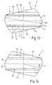
- FIG. 1b a side view is shown on a longitudinal side 38 of the cutting element 1.
- the orientation of this view is in the FIG. 1a indicated by an arrow Ib.
- the drill spiral 2 which receives the cutting element 1.
- the cutting element 1 has a nominal diameter DN in the head region I and in the foot region II which is greater than a helix diameter DW.
- the cutting element 1 protrudes with the front ends 36, 37 beyond a defined by the helical diameter DW cylinder Z and also acts with the foot area II on the material to be machined.
- a second transverse side 6, a second cutting edge 8, a main cutting edge 10, a rake surface 12, an open surface 14, a guide land 16 and a leading edge 18 of the cutting element 1 visible.
- the Figure 1c shows a section through the in the FIG. 1b illustrated cutting element 1 along the section line Ic-Ic.
- the separating element 1 again has the T-like shape T already known from the view on the transverse side, which makes the cutting element 1 solid and stable, especially in the foot region I.
- FIG. 1d is a bottom view of the in the FIG. 1b shown cutting elements 1 shown from an arrow direction Id.
- the bottom 33 of the cutting element 1 passes over the side surfaces 34, 35 in the lower sides 21, 22 and in the longitudinal sides 38, 39 via.
- Below cutting surfaces 11 and 12, the cutting element 1 is formed slender.
- Below free surfaces 13 and 14, the cutting element 1 is widened and solid.
- With a dashed line an alternative course of the longitudinal side 39 is indicated, with which a recess 40 is provided, which facilitates the chip removal on the cutting element 1.
- Such a recess can of course also on the longitudinal side 39 will be realized.
- the leading edge 17 extending into the plane of the drawing and the subsequent guiding phase 15 are identified.
- FIG 1e is a plan view of the end face 29 of the drill spiral 2 shown.
- the shoulders 24, 25 pass over the side walls 31, 32 into the floor 30.
- Through the course of the groove 28 can be seen as an inserted into the groove 28 cutting element 1 with its longitudinal sides 38 and 39 (see Figure 1d ) at an angle ⁇ obliquely to the side walls 31, 32 of the groove 28 stands.
- FIG. 2 shows a bottom view of another cutting element 1.
- a substantially foot portion II forming cuboid Q is aligned parallel to a head portion I and thus also to an end face of a drill spiral, not shown.
- An angle ⁇ , which defines the deviation, is thus 0 °.
- FIGS. 3a to 3e show in analogy to the Figure 1c Cross sections through five cutting elements, which have different foot areas.
- FIG. 3a shows a cutting element 1 in which a foot portion II side surfaces 34, 35 and lower sides 21, 22, which bulge convexly from a bottom 33.
- FIG. 3b shows a cutting element 1, in which a foot portion II side surfaces 34, 35 which, viewed in section from a bottom 33 of S-shape in the lower sides 21, 22 pass.
- the Figure 3c shows a cutting element 1, in which in a foot area II from a bottom 33 side surfaces 34, 35 go out, which pass at right angles into lower sides 21, 22.
- the 3d figure shows a cutting element 1, in which a foot portion II side surfaces 34, 35 and lower sides 21, 22, which bulge from a bottom 33 of concave.
- FIG. 3e shows a cutting element 1, wherein a foot portion II has a bottom 33, which, viewed in section merges into inclined side surfaces 34, 35 and lower sides 21, 22.
- the invention is not limited to illustrated or described embodiments. Rather, it includes developments of the invention within the scope of the patent claims.
- the invention also provides drilling tools which have more than two cutting edges.
- the drill bit then, for example, Y-shaped or X-shaped grooves, wherein the foot portion of the cutting element is then also X-shaped or Y-shaped and protrudes with its free ends of the groove on the drill spiral.
- the head region at least partially covers and supports the shoulders which form the grooves.
Landscapes
- Engineering & Computer Science (AREA)
- Geology (AREA)
- Life Sciences & Earth Sciences (AREA)
- Mining & Mineral Resources (AREA)
- Mechanical Engineering (AREA)
- Physics & Mathematics (AREA)
- Environmental & Geological Engineering (AREA)
- Fluid Mechanics (AREA)
- General Life Sciences & Earth Sciences (AREA)
- Geochemistry & Mineralogy (AREA)
- Drilling Tools (AREA)
- Cutting Tools, Boring Holders, And Turrets (AREA)
- Drilling And Boring (AREA)
- Earth Drilling (AREA)
Description
- Die Erfindung betrifft ein Bohrwerkzeug gemäß dem Oberbegriff des Anspruchs1.
- Aus der
DE OS 2 008 825 ist ein Bohrer mit einer Hartmetälleinlage bekannt, welche einen zapfenförmigen Ansatz aufweist und mit diesem in einer Bohrung in den Bohrerschaft eingesteckt und verlötet ist. Die den Bohrkopf bildende Hartmetalleinlage liegt auf stirnseitig am Bohrerschaft angeordneten Flächen auf. Nachteilig an einer derartigen Ausbildung des Bohrerkopfes bzw. der Verbindung des Bohrerkopfes mit dem Bohrerschaft ist, dass der aus teurem Hartmetall bestehende Ansatz des Bohrerkopfes ungenutzt für die Bearbeitung des zu bearbeitenden Materials innerhalb des Bohrerschafts liegt. - Weiterhin sind aus der
DE 43 39 245 A1 Spiralbohrer bekannt, welche Bohrerköpfe aufweisen, welche die Bohrerwendel uförmig übergreifen. Durch die Ausbildung von zwei Füssen am Bohrerkopf weisen derartige Bohrerköpfe ein großes Volumen auf. Weiterhin lässt sich ein Bohrerkopf mit Rücksprüngen in einem Press-Sinter-Verfahren nur mit erhöhtem Aufwand herstellen. - Aus der
EP1 024 247 A1 ist ein Bohrwerkzeug mit einem Schaft und einem Bohrkopf bekannt, wobei der Schaft mit einem Schlitz versehen ist, in welchem eine Bohrplatte angeordnet ist, wobei die Bohrplatte in einer Draufsicht parallel zur Mittellängsachse des Bohrwerkzeugs betrachtet eine rechteckige Grundform hat und wobei an zwei einander diametral gegenüberliegenden Ecken jeweils eine dreiecksförmige Verbreiterung der Bohrplatte vorgesehen ist. - Aus der
US 4,889,320 ist ein Gesteinsbohrer mit eingängigem oder zweigängigem Spiralschaft und mit wenigstens einer, sich über den gesamten Durchmesser des Bohrerkopfes erstreckenden,` dachförmig geneigten, Schneiden aufweisenden Schneidplatte aus Hartmetall bekannt, wobei der Bohrerkopf im Querschnitt quadratisch, nahezu quadratisch oder rechteckformig ausgebildet ist, wobei die Schneidplatte oder die Kreüzschneidplatten zu den Eckbereichen oder zu den Seitenflächen des Bohrerkopfes hin ausgerichtet sind und über die Umfangskontur des Bohrerkopfes hinausragen. - Aus der
EP 1 302 290 A1 ist ein Bohrwerkzeug mit einem Ein- oder Mehrschneiden-Werkzeugkopf mit wenigstens einem Schneidkörper bekannt, welcher in einem Schlitz aufgenommen ist, wobei der Schneidkörper einen dachförmig ausgebildeten zentrischen Bereich umfasst, der seitlich von zwei in Wirkrichtung des Bohrers zurückversetzten Außenbereichen begrenzt ist und wobei die Anschliffflächen des zentrischen Bereichs eine pyramidenförmige Spitze unter Vermeidung der Bildung einer Querschneide ausbilden. - Aus der
US 5,265,688 ist schließlich ein Gesteinsbohrer mit Schaft und einem Bohrkopf bekannt, der auf seiner in Vorschubrichtung weisenden Stirnseite eine zumindest über den Durchmesser sich erstreckende Schneidplatte und mindestens zwei Schneidstifte aufweist, wobei die Schneidplatte in einem Schlitz aufgenommen ist. - Aufgabe der Erfindung ist es, ein Bohrwerkzeug vorzuschlagen, bei welchem ein Schneidelement bzw. ein Bohrerkopf optimal für die Bearbeitung des zu bohrenden Materials eingesetzt werden und bei welchem Materialanhäufungen in Bereichen ohne Bearbeitungsfunktion weitestgehend vermieden sind.
- Diese Aufgabe wird ausgehend von den Merkmalen des Oberbegriffs des Anspruchs 1 erfindungsgemäß durch die kennzeichnenden Merkmale des Anspruchs 1 gelöst. In den Unteransprüchen sind vorteilhafte und zweckmäßige Weiterbildungen angegeben.
- Der Erfindung liegt der Kerngedanke zu Grunde, ein Bohrwerkzeug mit einem Schneidelement zu schaffen, bei welchem mit einem minimalen Aufwand an dem Werkstoff, welcher für das Schneidelement Verwendung findet, wie z.B. Hartmetall oder PKD, eine maximale Bohr- bzw. Schlagbohrwirkung erzielbar ist, wobei das Schneidelement zur Erhaltung der Eigenstabilität dennoch eine massive, kompakte und gedrungene Gestalt aufweist.
- Die Erfindung sieht vor, die Bohrerwendel stirnseitig mit einem Schlitz zu versehen, welcher die Bohrerwendel seitlich und zur Stirnseite öffnet, wobei der Fußbereich des Schneidelements, welches quer zum Verlauf einer Längsmittelebene durchgehend T-förmige Querschnitte aufweist, vom Schlitz aufgenommen wird und seitlich über diesen hinausragt. Hierbei erstrecken sich die Führungsfasen des Schneidelements jeweils etwa parallel zu einer Bohrerlängsachse durchgehend am Umfang des Schneidelements über den Kopfbereich und den Fußbereich des Schneidelements. Hierdurch erhält der Fußbereich des Schneidelements eine Doppelfunktion. Der Fußbereich dient der Verbindung zwischen Schneidelement und Bohrerwendel und ermöglicht neben einer optimalen Schlagkraftübertragung über die quer zur Bohrerlängsachse orientierten Flächen eine Übertragung hoher Drehmomente über die formschlüssige Verbindung. Weiterhin übernimmt der Fußbereich dadurch, dass dieser einen Durchmesser im Bereich des Nenndurchmessers aufweist, Aufgaben, welche bisher nur vom Kopfbereich des Schneidelements übernommen werden. Denn der Fußbereich weist Führungsfasen auf, welche als Verlängerungen der Führungsfasen des Kopfbereichs ausgebildet sind. Durch diese Funktionsübertragung auf den Fußbereich des Schneidelements ist es möglich das Schneidelement in unteren seitlichen Bereichen etwa um die Höhe des Fußbereichs niedriger auszubilden und dennoch eine vorgeschriebene Mindesthöhe der Schneidplatte zu erhalten.
- Weiterhin sieht die Erfindung vor, an der Führungsfase eine Führungskante auszubilden, welche sich insbesondere durchgehend über den Kopfbereich und den Fußbereich erstreckt. Durch diese lange Führungskante ist es möglich, bei geringer Reibung eine besonderes gute Führung an der Bohrlochwand zu gewährleisten.
- Erfindungsgemäß ist es vorgesehen, das Schneidelement mit Seitenflächen zu versehen, welche sich in Wirkrichtung des Bohrwerkzeugs V-förmig öffnen und zur Bohrerlängsachse einen Winkel von 2° bis 45° und insbesondere 15° aufweisen. Dies erlaubt ein einfaches Entformen des Schneidelements, wenn dieses beispielsweise in einem Press-Sinter-Verfahren hergestellt wird. Weiterhin werden durch eine solche Formgebung die an der Bohrerwendel und am Schneidelement auftretenden Kerbwirkungen minimiert.
- Die Erfindung sieht auch vor, den Fußbereich des Schneidelements in einem Winkel λ schräg zu dem stirnseitigen Ende der Bohrerwendel bzw. zu dem Schlitz im stirnseitigen Ende der Bohrerwendel anzuordnen, wobei für den Winkel λ gilt 3° ≤ λ ≤ 15° und insbesondere λ ≈ 6°. Hierdurch ist es möglich, den Bohrerkopf in seinem Fußbereich besonders gut abzustützen, da die Bohrerwendel mit einer massiv ausgebildeten Schulter in Drehrichtung auf den Bohrerkopf wirkt. Beispielsweise sind für die folgenden Bohrerdurchmesser die folgenden Winkel λ vorgesehen.
Bohrerdurchmesser in mm 6 10 16 Winkel λ 7, 6° 5,8° 4,7° - Weiterhin sieht die Erfindung vor, die Seitenflächen des Schneidelements symmetrisch zu der durch das Schneidelement bzw. den Schlitz definierten Längsmittelebene auszurichten. Hierdurch ist das Einsetzen des Schneidelements in die Bohrerwendel erleichtert, da beim Einsetzen nicht auf die Orientierung des Scheidelements geachtet werden muss, da das Schneidelement auch um 180° um die Bohrerlängsachse gedreht einsetzbar ist.
- Schließlich sieht die Erfindung vor, die Seitenwände konkav oder konvex oder s-förmig auszubilden. Dies erlaubt eine materialsparende bzw. eine besonders massive bzw. eine Kanten vermeidende Konstruktion des Schneidelements.
- Die Erfindung sieht auch noch vor, an wenigstens eine der Längsseiten des Bohrerkopfs wenigstens eine Aussparung auszubilden, welche etwa parallel zur Bohrerlängsachse verläuft. Hierdurch ist es möglich, die Abfuhr von Bohrmehl bzw. Bohrklein effektiver zu gestalten.
- Weitere Einzelheiten der Erfindung werden in der Zeichnung anhand von schematisch dargestellten Ausführungsbeispielen beschrieben.
- Hierbei zeigt:
- Figur 1a:
- eine Stirnansicht eines als Vollhartmetallkopf ausgebildeten Schneidelements und eines schematisch angedeuteten Abschnitts einer Bohrerwendel,
- Figur 1b:
- eine Seitenansicht des in der
Figur 1a dargestellten Schneidelements, - Figur 1c:
- einen Schnitt durch das in der
Figur 1b dargestellte Schneidelement entlang der Schnittlinie Ic-Ic, - Figur 1d:
- eine Unteransicht des in der
Figur 1b dargestellten Schneidelements aus einer Pfeilrichtung Id, - Figur 1e:
- eine Draufsicht auf die in der
Figur 1a dargestellte Bohrerwendel aus einer Pfeilrichtung Ie, - Figur 2:
- eine Unteransicht eines weiteren Schneidelements und
- Figur 3a-3e:
- fünf Ausführungsvarianten eines Schneidelements.
- In der
Figur 1a sind ein als Vollhartmetallkopf ausgebildetes Schneidelement 1 und ein schematisch angedeuteter Abschnitt einer Bohrerwendel 2 eines nicht weiter dargestellten Bohrwerkzeugs 3 in einer sogenannten Explosionsansicht dargestellt. Das Schneidelement 1 bildet einen Bohrerkopf 4. In der Stirnansicht auf eine Querseite 5 des Schneidelements 1 sind von einer ersten Schneide 7 eine Hauptschneide 9, welche durch eine Spanfläche 11 und eine Freifläche 13 gebildet wird, und eine Führungsfase 15 mit einer Führungskante 17 zu sehen, welche parallel zu einer Bohrerlängsachse 19 verlaufen, die in einer Längsmittelebene 20 liegt. Das Schneidelement 1 bzw. der Bohrerkopf 4 besteht aus einem Kopfbereich I und einem Fußbereich II. Diese beiden Bereiche I und II gehen im Bereich einer Querebene 23, welche von der Bohrerlängsachse 19 im rechten Winkel geschnitten wird, ineinander über. Mit Unterseiten 21, 22 liegt das Schneidelement 1 auf Schultern 24, 25 von Stegen 26, 27 auf, welche einen Schlitz bzw. eine Nut 28 an einem stirnseitigen Ende 29 der Bohrerwendel 2 bilden. Die Nut 28 ist durch einen Boden 30 und Seitenwände 31, 32 begrenzt. Bei eingesetztem Schneidelement 1 liegt dieses mit einem Boden 33 unter Ausbildung eines Lötspalts auf dem Boden 30 der Nut 28 auf. Weiterhin liegen Seitenflächen 34, 35 des Fußbereichs II des Schneidelements 1 an den Seitenwänden 31, 32 der Nut 28 an. Somit ist das in der Ansicht auf die Stirnseite 5 T-förmige Schneidelement 1 in die Nut 28 eingebettet und ragt lediglich mit seinem Kopfbereich I und stirnseitigen Enden 36, 37 (siehe auchFigur 1b ) über die Nut 28 bzw. die Bohrerwendel 2 seitlich hinaus. Die Bohrerwendel 2 geht in einen nicht dargestellten Einspannschaft über, welcher als Systemeinsteckende und insbesondere als SDS-Plus-Einspannschaft ausgebildet ist. Auf die Darstellung von an der Bohrerwendel 2 vorhandenen Bohrmehlnuten wurde zur Vereinfachung derFigur 1a verzichtet. Die Führungsfase 15 weist im Kopfbereich I des Schneidelements 1 eine maximale Höhe H1 auf. Die in den Fußbereich II fortgeführte Führungsfase 15 weist dort eine Höhe H2 auf. Somit besitzt die Führungsfase 15 eine Gesamthöhe H3, welche sich aus der Summe der Höhen H1 und H2 ergibt. Das heißt, die üblicherweise allein durch den Kopfbereich I des Schneidelements 1 gebildete Führungsfase 15 ist um den Wert H2 erhöht, so dass das Bohrwerkzeug 3 besser geführt ist bzw. bei niedrigerer Kopfhöhe H4 ein besseres Führungsverhalten aufweist. Der Fußbereich II besteht im wesentlichen aus einem Quader Q, welcher seitlich aus der am stirnseitigen Ende 29 der Bohrerwendel 2 angeordneten Nut 28 heraussteht. Die Nut 28 weist im Bereich ihres Bodens 30 eine Breite B1 auf, welche sich in eine Wirkrichtung w des Bohrwerkzeugs 3 vergrößert und beispielsweise am Übergang der Seitenwände 31, 32 in die Schultern 24, 25 auf eine Breite B2 angewachsen ist. - In der
Figur 1b ist eine Seitenansicht auf eine Längsseite 38 des Schneidelements 1 dargestellt. Die Orientierung dieser Ansicht ist in derFigur 1a durch einen Pfeil Ib angedeutet. In derFigur 1b ist mit gestrichelten Linien die Bohrerwendel 2 angedeutet, welche das Schneidelement 1 aufnimmt. Das Schneidelement 1 weist im Kopfbereich I und im Fußbereich II einen Nenndurchmesser DN auf, welcher größer ist als ein Wendeldurchmesser DW. Somit ragt das Schneidelement 1 mit den stirnseitigen Enden 36, 37 über einen durch den Wendeldurchmesser DW definierten Zylinder Z hinaus und wirkt auch mit dem Fußbereich II auf das zu bearbeitende Material ein. Weiterhin sind in derFigur 1b eine zweite Querseite 6, eine zweite Schneide 8, eine Hauptschneide 10, eine Spanfläche 12, eine Freifläche 14, eine Führungsfase 16 und eine Führungskante 18 des Schneidelements 1 sichtbar. - Die
Figur 1c zeigt einen Schnitt durch das in derFigur 1b dargestellte Schneidelement 1 entlang der Schnittlinie Ic-Ic. In der Schnittdarstellung weist das Scheidelement 1 wiederum die bereits aus der Ansicht auf die Querseite bekannte T-ähnliche Gestalt T auf, welche das Schneidelement 1 besonders im Fußbereich I massiv und stabil macht. - In der
Figur 1d ist eine Unteransicht des in derFigur 1b dargestellten Schneidelements 1 aus einer Pfeilrichtung Id dargestellt. Der Boden 33 des Schneidelements 1 geht über die Seitenflächen 34, 35 in die Unterseiten 21, 22 und in die Längsseiten 38, 39 über. Unterhalb von Spanflächen 11 bzw. 12 ist das Schneidelement 1 schlank ausgebildet. Unterhalb von Freiflächen 13 bzw. 14 ist das Schneidelement 1 verbreitert und massiv ausgebildet. Mit einer gestrichelten Linie ist ein alternativer Verlauf der Längsseite 39 angedeutet, mit welchem eine Aussparung 40 geschaffen wird, welche die Spanabfuhr am Schneidelement 1 erleichtert. Eine derartige Aussparung kann selbstverständlich auch an der Längsseite 39 realisiert werden. Weiterhin sind die in die Zeichnungsebene hineinverlaufende Führungskante 17 und die sich an diese anschließende Führungsphase 15 gekennzeichnet. - In der
Figur 1e ist eine Draufsicht auf die Stirnseite 29 der Bohrerwendel 2 abgebildet. Die Schultern 24, 25 gehen über die Seitenwände 31, 32 in den Boden 30 über. Die tiefer in der Zeichnungsebene liegende Bohrmehlnut der Bohrerwendel ist nicht dargestellt. Durch den Verlauf der Nut 28 ist erkennbar wie ein in die Nut 28 eingesetztes Schneidelement 1 mit seinen Längsseiten 38 bzw. 39 (sieheFigur 1d ) in einem Winkel λ schräg zu den Seitenwänden 31, 32 der Nut 28 steht. - Die
Figur 2 zeigt eine Unteransicht eines weiteren Schneidelements 1. Bei diesem ist ein im wesentlichen einen Fußbereich II bildender Quader Q parallel zu einem Kopfbereich I und somit auch zu einem nicht dargestellten stirnseitigen Ende einer Bohrwendel ausgerichtet. Ein Winkel λ, welcher die Abweichung definiert, beträgt somit 0°. - Die
Figuren 3a bis 3e zeigen in Analogie zu derFigur 1c Querschnitte durch fünf Schneidelemente, welche unterschiedliche Fußbereiche aufweisen. - Die
Figur 3a zeigt ein Schneidelement 1 bei welchem ein Fußbereich II Seitenflächen 34, 35 bzw. Unterseiten 21, 22 aufweist, welche sich von einem Boden 33 aus konvex wölben. - Die
Figur 3b zeigt ein Schneidelement 1, bei welchem ein Fußbereich II Seitenflächen 34, 35 aufweist, welche im Schnitt betrachtet von einem Boden 33 aus S-förmig in Unterseiten 21, 22 übergehen. - Die
Figur 3c zeigt ein Schneidelement 1, bei welchem in einem Fußbereich II von einem Boden 33 Seitenflächen 34, 35 ausgehen, die rechtwinklig in Unterseiten 21, 22 übergehen. - Die
Figur 3d zeigt ein Schneidelement 1, bei welchem ein Fußbereich II Seitenflächen 34, 35 bzw. Unterseiten 21, 22 aufweist, welche sich von einem Boden 33 aus konkav wölben. - Die
Figur 3e zeigt ein Schneidelement 1, bei welchem ein Fußbereich II einen Boden 33 aufweist, welcher im Schnitt betrachtet in schräg verlaufende Seitenflächen 34, 35 bzw. Unterseiten 21, 22 übergeht. - Die Erfindung ist nicht auf dargestellte oder beschriebene Ausführungsbeispiele beschränkt. Sie umfasst vielmehr Weiterbildungen der Erfindung im Rahmen der Schutzrechtsansprüche. Die Erfindung sieht auch Bohrwerkzeuge vor, welche mehr als zwei Schneiden aufweisen. Bei diesen weist die Bohrerwendel dann beispielsweise Y-förmige oder X-förmige Nuten auf, wobei der Fußbereich des Schneidelements dann ebenfalls X-förmig oder Y-förmig ausgebildet ist und mit seinen freien Enden aus der Nut über die Bohrerwendel hinaussteht. Somit ist dann bei drei oder mehr Führungsfasen eine Verlängerung der Führungsfase bis in den Fußbereich möglich. Bei derartigen Bohrwerkzeugen überdeckt der Kopfbereich die Schultern, welche die Nuten bilden, zumindest teilweise und stützt sich auf diesen ab.
-
- 1
- Schneidelement
- 2
- Bohrerwendel
- 3
- Bohrwerkzeug
- 4
- Bohrerkopf
- 5, 6
- Querseite von 1
- 7, 8
- erste bzw. zweite Schneide von 1
- 9, 10
- Hauptschneidkante
- 11, 12
- Spanfläche
- 13, 14
- Freifläche
- 15, 16
- Führungsfase
- 17, 18
- Führungskante
- 19
- Bohrerlängsachse
- 20
- Längsmittelebene
- 21, 22
- Unterseite von I
- 23
- Querebene zwischen I und II
- 24, 25
- Schulter von 26 bzw. 27
- 26, 27
- Steg an 2
- 28
- Schlitz, Nut
- 29
- stirnseitiges Ende von 2
- 30
- Boden von 28
- 31, 32
- Seitenwand von 28
- 33
- Boden von 1
- 34, 35
- Seitenfläche von II
- 36, 37
- stirnseitiges Ende von II
- 38, 39
- Längsseiten von 1
- 40
- Aussparung an 39
- B1, B2
- Breite von 28
- DN
- Nenndurchmesser von 1
- DW
- Wendeldurchmesser
- H1
- Höhe von 15 bzw. 16 im Bereich I
- H2
- Höhe von 15 bzw. 16 im Bereich II
- H3
- Höhe von 15 bzw. 16 im Bereich I und II
- H4
- Kopfhöhe
- Q
- Quader
- T
- T-ähnliche Gestalt
- Z
- Zylinder
- w
- Wirkrichtung von 3
- α
- Winkel zwischen 31 bzw. 32 und 19
- λ
- Winkel zwischen 38 bzw. 39 und 31 bzw. 32
Claims (7)
- Bohrwerkzeug (3) mit einem als Vollhartmetallkopf ausgebildeten Schneidelement(1) als Bohrerkopf (4), einer sich an den Bohrerkopf (4) anschließenden Bohrerwendel (2) und einem nachfolgenden Einspannschaft, wobei der Bohrerkopf (4) mit einem Fußbereich (II) in einem Rücksprung (28) der Bohrerwendel (2) gehalten ist, wobei der Bohrerkopf (4) mit einer Unterseite (21, 22) eines Kopfbereichs (I) auf einem stirnseitigen Ende (29) der Bohrerwendel (2) aufliegt und wobei der Bohrerkopf (4) am Kopfbereich (I) wenigstens zwei Führungsfasen (15, 16) aufweist, dadurch gekennzeichnet, dass der Rücksprung (28) in der Bohrerwendel (2) als Schlitz (28) ausgebildet ist, welcher die Bohrerwendel (2) seitlich öffnet, dass das Schneidelement (1) quer zum Verlauf einer Längsmittelebene (20) durchgehend T-förmige Querschnitte aufweist und mit seinem Fußbereich (II) seitlich aus der Bohrerwendel (2) herausragt und dass sich die Führungsfasen (15, 16) des Schneidelements (1) jeweils etwa parallel zu einer Bohrerlängsachse (19) durchgehend über den Kopfbereich (I) und den Fußbereich (II) des Schneidelements(1) erstrecken.
- Bohrwerkzeug nach Anspruch 1, dadurch gekennzeichnet, dass die Führungsfase (15, 16) eine Führungskante (17, 18) aufweist, welche sich insbesondere durchgehend über die gesamte Höhe (H3) der Führungsfase (15, 16) erstreckt.
- Bohrwerkzeug nach einem der vorhergehenden Ansprüche, dadurch gekennzeichnet, dass sich die Breite (B1; B2) des Schlitzes (28) in Wirkrichtung (w) des Bohrwerkzeugs (3) vergrößert und die Seitenwände (31, 32) zur Bohrerlängsachse (19) einen Winkel (α) von 2° bis 45° und insbesondere α = 15° aufweisen.
- Bohrwerkzeug nach einem der vorhergehenden Ansprüche, dadurch gekennzeichnet, dass der Fußbereich (II) in einem Winkel (λ) schräg zu dem stirnseitigen Ende (29) der Bohrerwendel (2) steht, wobei für den Winkel λ gilt 3° ≤ λ ≤ 15° und insbesondere λ ≈ 6°.
- Bohrwerkzeug nach einem der vorhergehenden Ansprüche, dadurch gekennzeichnet, dass die Seitenflächen (34, 35) symmetrisch zu der Längsmittelebene (20) angeordnet sind.
- Bohrwerkzeug nach einem der vorhergehenden Ansprüche, dadurch gekennzeichnet, dass die Seitenflächen (34, 35) konkav oder konvex oder s-förmig ausgebildet sind.
- Bohrwerkzeug nach einem der vorhergehenden Ansprüche, dadurch gekennzeichnet, dass wenigstens eine der Längsseiten (38, 39) des Bohrerkopfs (4) wenigstens eine etwa parallel zur Bohrerlängsachse verlaufende Aussparung (40) aufweist.
Applications Claiming Priority (2)
| Application Number | Priority Date | Filing Date | Title |
|---|---|---|---|
| DE10361501A DE10361501A1 (de) | 2003-12-23 | 2003-12-23 | Bohrwerkzeug |
| PCT/DE2004/002400 WO2005061838A1 (de) | 2003-12-23 | 2004-10-28 | Bohrwerkzeug |
Publications (2)
| Publication Number | Publication Date |
|---|---|
| EP1702134A1 EP1702134A1 (de) | 2006-09-20 |
| EP1702134B1 true EP1702134B1 (de) | 2008-03-05 |
Family
ID=34706641
Family Applications (1)
| Application Number | Title | Priority Date | Filing Date |
|---|---|---|---|
| EP04802653A Expired - Lifetime EP1702134B1 (de) | 2003-12-23 | 2004-10-28 | Bohrwerkzeug |
Country Status (5)
| Country | Link |
|---|---|
| EP (1) | EP1702134B1 (de) |
| JP (1) | JP2007515302A (de) |
| AT (1) | ATE388300T1 (de) |
| DE (2) | DE10361501A1 (de) |
| WO (1) | WO2005061838A1 (de) |
Cited By (1)
| Publication number | Priority date | Publication date | Assignee | Title |
|---|---|---|---|---|
| DE102012218702A1 (de) | 2012-10-15 | 2014-04-17 | Robert Bosch Gmbh | Gesteinsbohrer |
Families Citing this family (3)
| Publication number | Priority date | Publication date | Assignee | Title |
|---|---|---|---|---|
| DE102006035443B3 (de) * | 2006-11-15 | 2008-02-21 | Hilti Ag | Bohrwerkzeug mit Hartstoffkopf |
| DE102007020051B4 (de) * | 2007-04-27 | 2013-11-21 | Irwin Industrial Tool Company | Hartmetallplatte für Gesteinsbohrer und Gesteinsbohrer |
| GB201109864D0 (en) * | 2011-06-13 | 2011-07-27 | Element Six Ltd | Blank bodies for drill tips and methods for making same |
Family Cites Families (4)
| Publication number | Priority date | Publication date | Assignee | Title |
|---|---|---|---|---|
| DE3707798A1 (de) * | 1987-03-11 | 1988-09-22 | Hawera Probst Kg Hartmetall | Gesteinsbohrer |
| US5265688A (en) * | 1990-04-09 | 1993-11-30 | Hilti Aktiengesellschaft | Rock drill |
| DE29901285U1 (de) * | 1999-01-26 | 1999-06-17 | Plica Werkzeugfabrik Ag, Mollis | Bohrwerkzeug |
| EP1302290B1 (de) * | 2001-10-12 | 2008-07-02 | Robert Bosch Gmbh | Bohrwerkzeug |
-
2003
- 2003-12-23 DE DE10361501A patent/DE10361501A1/de not_active Withdrawn
-
2004
- 2004-10-28 DE DE502004006450T patent/DE502004006450D1/de not_active Expired - Lifetime
- 2004-10-28 JP JP2006545899A patent/JP2007515302A/ja not_active Withdrawn
- 2004-10-28 EP EP04802653A patent/EP1702134B1/de not_active Expired - Lifetime
- 2004-10-28 AT AT04802653T patent/ATE388300T1/de not_active IP Right Cessation
- 2004-10-28 WO PCT/DE2004/002400 patent/WO2005061838A1/de not_active Ceased
Cited By (2)
| Publication number | Priority date | Publication date | Assignee | Title |
|---|---|---|---|---|
| DE102012218702A1 (de) | 2012-10-15 | 2014-04-17 | Robert Bosch Gmbh | Gesteinsbohrer |
| RU2639746C2 (ru) * | 2012-10-15 | 2017-12-22 | Роберт Бош Гмбх | Бур |
Also Published As
| Publication number | Publication date |
|---|---|
| JP2007515302A (ja) | 2007-06-14 |
| ATE388300T1 (de) | 2008-03-15 |
| EP1702134A1 (de) | 2006-09-20 |
| DE10361501A1 (de) | 2005-07-28 |
| WO2005061838A1 (de) | 2005-07-07 |
| DE502004006450D1 (de) | 2008-04-17 |
Similar Documents
| Publication | Publication Date | Title |
|---|---|---|
| EP1675699B1 (de) | Schneidkörper, insbesondere zum stech- und längsdrehen | |
| DE69409364T2 (de) | Schneideinsatz mit spiralförmiger erhabener fläche und angrenzender ausnehmung | |
| DE3339211C2 (de) | ||
| EP1302290B1 (de) | Bohrwerkzeug | |
| EP0715055B1 (de) | Werkzeug mit Trägerkörper und Schneidkörper | |
| EP0657617B1 (de) | Gesteinsbohrer | |
| EP3038776B1 (de) | Bohrer | |
| DE202009005847U1 (de) | Gesteinsbohrer | |
| EP1259699B1 (de) | Gesteinsbohrer | |
| EP1599307A1 (de) | Wendeplatte zum fasen mittels eines könischen fräskopfes | |
| DE69611810T2 (de) | Schneideinsatz für Fräs-Meissel | |
| WO2005061160A1 (de) | Mehrzweckbohrwerkzeug | |
| DE102007062539B4 (de) | Bohrwerkzeug | |
| EP1316669A2 (de) | Gesteinbohrwerkzeug | |
| DE3742661A1 (de) | Gesteinsbohrer | |
| DE69525979T2 (de) | Schneidwerkzeug zum bohren von beton, agglomeraten oder mauerwerk | |
| DE3601315A1 (de) | Befestiger | |
| DE19734094A1 (de) | Gesteinsbohrer | |
| DE3126355C2 (de) | Bohrschraube | |
| EP1431511B1 (de) | Gesteinsbohrer | |
| EP1797277B1 (de) | Bohrwerkzeug mit einem als platte oder kopf ausgebildeten schneidelement | |
| EP1985794B1 (de) | Hartmetallplatte für Gesteinsbohrer und Gesteinsbohrer | |
| EP1340604A2 (de) | Bohrwerkzeug | |
| EP0516581B1 (de) | Bohr- und Meisselwerkzeug mit Grundkörper und Schneidkörper | |
| DE10208630A1 (de) | Bohrwerkzeug |
Legal Events
| Date | Code | Title | Description |
|---|---|---|---|
| PUAI | Public reference made under article 153(3) epc to a published international application that has entered the european phase |
Free format text: ORIGINAL CODE: 0009012 |
|
| 17P | Request for examination filed |
Effective date: 20060724 |
|
| AK | Designated contracting states |
Kind code of ref document: A1 Designated state(s): AT BE BG CH CY CZ DE DK EE ES FI FR GB GR HU IE IT LI LU MC NL PL PT RO SE SI SK TR |
|
| DAX | Request for extension of the european patent (deleted) | ||
| 17Q | First examination report despatched |
Effective date: 20070312 |
|
| GRAP | Despatch of communication of intention to grant a patent |
Free format text: ORIGINAL CODE: EPIDOSNIGR1 |
|
| GRAS | Grant fee paid |
Free format text: ORIGINAL CODE: EPIDOSNIGR3 |
|
| GRAA | (expected) grant |
Free format text: ORIGINAL CODE: 0009210 |
|
| AK | Designated contracting states |
Kind code of ref document: B1 Designated state(s): AT BE BG CH CY CZ DE DK EE ES FI FR GB GR HU IE IT LI LU MC NL PL PT RO SE SI SK TR |
|
| REG | Reference to a national code |
Ref country code: GB Ref legal event code: FG4D Free format text: NOT ENGLISH |
|
| REG | Reference to a national code |
Ref country code: CH Ref legal event code: EP |
|
| REG | Reference to a national code |
Ref country code: IE Ref legal event code: FG4D Free format text: LANGUAGE OF EP DOCUMENT: GERMAN |
|
| REF | Corresponds to: |
Ref document number: 502004006450 Country of ref document: DE Date of ref document: 20080417 Kind code of ref document: P |
|
| PG25 | Lapsed in a contracting state [announced via postgrant information from national office to epo] |
Ref country code: ES Free format text: LAPSE BECAUSE OF FAILURE TO SUBMIT A TRANSLATION OF THE DESCRIPTION OR TO PAY THE FEE WITHIN THE PRESCRIBED TIME-LIMIT Effective date: 20080616 Ref country code: FI Free format text: LAPSE BECAUSE OF FAILURE TO SUBMIT A TRANSLATION OF THE DESCRIPTION OR TO PAY THE FEE WITHIN THE PRESCRIBED TIME-LIMIT Effective date: 20080305 |
|
| NLV1 | Nl: lapsed or annulled due to failure to fulfill the requirements of art. 29p and 29m of the patents act | ||
| PG25 | Lapsed in a contracting state [announced via postgrant information from national office to epo] |
Ref country code: PL Free format text: LAPSE BECAUSE OF FAILURE TO SUBMIT A TRANSLATION OF THE DESCRIPTION OR TO PAY THE FEE WITHIN THE PRESCRIBED TIME-LIMIT Effective date: 20080305 Ref country code: SI Free format text: LAPSE BECAUSE OF FAILURE TO SUBMIT A TRANSLATION OF THE DESCRIPTION OR TO PAY THE FEE WITHIN THE PRESCRIBED TIME-LIMIT Effective date: 20080305 |
|
| REG | Reference to a national code |
Ref country code: IE Ref legal event code: FD4D |
|
| PG25 | Lapsed in a contracting state [announced via postgrant information from national office to epo] |
Ref country code: PT Free format text: LAPSE BECAUSE OF FAILURE TO SUBMIT A TRANSLATION OF THE DESCRIPTION OR TO PAY THE FEE WITHIN THE PRESCRIBED TIME-LIMIT Effective date: 20080805 Ref country code: SE Free format text: LAPSE BECAUSE OF FAILURE TO SUBMIT A TRANSLATION OF THE DESCRIPTION OR TO PAY THE FEE WITHIN THE PRESCRIBED TIME-LIMIT Effective date: 20080605 Ref country code: SK Free format text: LAPSE BECAUSE OF FAILURE TO SUBMIT A TRANSLATION OF THE DESCRIPTION OR TO PAY THE FEE WITHIN THE PRESCRIBED TIME-LIMIT Effective date: 20080305 Ref country code: CZ Free format text: LAPSE BECAUSE OF FAILURE TO SUBMIT A TRANSLATION OF THE DESCRIPTION OR TO PAY THE FEE WITHIN THE PRESCRIBED TIME-LIMIT Effective date: 20080305 Ref country code: NL Free format text: LAPSE BECAUSE OF FAILURE TO SUBMIT A TRANSLATION OF THE DESCRIPTION OR TO PAY THE FEE WITHIN THE PRESCRIBED TIME-LIMIT Effective date: 20080305 |
|
| PG25 | Lapsed in a contracting state [announced via postgrant information from national office to epo] |
Ref country code: RO Free format text: LAPSE BECAUSE OF FAILURE TO SUBMIT A TRANSLATION OF THE DESCRIPTION OR TO PAY THE FEE WITHIN THE PRESCRIBED TIME-LIMIT Effective date: 20080305 |
|
| EN | Fr: translation not filed | ||
| PLBE | No opposition filed within time limit |
Free format text: ORIGINAL CODE: 0009261 |
|
| STAA | Information on the status of an ep patent application or granted ep patent |
Free format text: STATUS: NO OPPOSITION FILED WITHIN TIME LIMIT |
|
| PG25 | Lapsed in a contracting state [announced via postgrant information from national office to epo] |
Ref country code: IE Free format text: LAPSE BECAUSE OF FAILURE TO SUBMIT A TRANSLATION OF THE DESCRIPTION OR TO PAY THE FEE WITHIN THE PRESCRIBED TIME-LIMIT Effective date: 20080305 Ref country code: DK Free format text: LAPSE BECAUSE OF FAILURE TO SUBMIT A TRANSLATION OF THE DESCRIPTION OR TO PAY THE FEE WITHIN THE PRESCRIBED TIME-LIMIT Effective date: 20080305 |
|
| 26N | No opposition filed |
Effective date: 20081208 |
|
| BERE | Be: lapsed |
Owner name: ROBERT BOSCH G.M.B.H. Effective date: 20081031 |
|
| PG25 | Lapsed in a contracting state [announced via postgrant information from national office to epo] |
Ref country code: BG Free format text: LAPSE BECAUSE OF FAILURE TO SUBMIT A TRANSLATION OF THE DESCRIPTION OR TO PAY THE FEE WITHIN THE PRESCRIBED TIME-LIMIT Effective date: 20080605 Ref country code: EE Free format text: LAPSE BECAUSE OF FAILURE TO SUBMIT A TRANSLATION OF THE DESCRIPTION OR TO PAY THE FEE WITHIN THE PRESCRIBED TIME-LIMIT Effective date: 20080305 Ref country code: FR Free format text: LAPSE BECAUSE OF FAILURE TO SUBMIT A TRANSLATION OF THE DESCRIPTION OR TO PAY THE FEE WITHIN THE PRESCRIBED TIME-LIMIT Effective date: 20081226 |
|
| PG25 | Lapsed in a contracting state [announced via postgrant information from national office to epo] |
Ref country code: MC Free format text: LAPSE BECAUSE OF NON-PAYMENT OF DUE FEES Effective date: 20081031 |
|
| REG | Reference to a national code |
Ref country code: CH Ref legal event code: PL |
|
| GBPC | Gb: european patent ceased through non-payment of renewal fee |
Effective date: 20081028 |
|
| PG25 | Lapsed in a contracting state [announced via postgrant information from national office to epo] |
Ref country code: IT Free format text: LAPSE BECAUSE OF FAILURE TO SUBMIT A TRANSLATION OF THE DESCRIPTION OR TO PAY THE FEE WITHIN THE PRESCRIBED TIME-LIMIT Effective date: 20080305 |
|
| PG25 | Lapsed in a contracting state [announced via postgrant information from national office to epo] |
Ref country code: CY Free format text: LAPSE BECAUSE OF FAILURE TO SUBMIT A TRANSLATION OF THE DESCRIPTION OR TO PAY THE FEE WITHIN THE PRESCRIBED TIME-LIMIT Effective date: 20080305 Ref country code: BE Free format text: LAPSE BECAUSE OF NON-PAYMENT OF DUE FEES Effective date: 20081031 |
|
| PG25 | Lapsed in a contracting state [announced via postgrant information from national office to epo] |
Ref country code: LI Free format text: LAPSE BECAUSE OF NON-PAYMENT OF DUE FEES Effective date: 20081031 Ref country code: CH Free format text: LAPSE BECAUSE OF NON-PAYMENT OF DUE FEES Effective date: 20081031 |
|
| PG25 | Lapsed in a contracting state [announced via postgrant information from national office to epo] |
Ref country code: GB Free format text: LAPSE BECAUSE OF NON-PAYMENT OF DUE FEES Effective date: 20081028 |
|
| PG25 | Lapsed in a contracting state [announced via postgrant information from national office to epo] |
Ref country code: AT Free format text: LAPSE BECAUSE OF NON-PAYMENT OF DUE FEES Effective date: 20081028 |
|
| PG25 | Lapsed in a contracting state [announced via postgrant information from national office to epo] |
Ref country code: LU Free format text: LAPSE BECAUSE OF NON-PAYMENT OF DUE FEES Effective date: 20081028 Ref country code: HU Free format text: LAPSE BECAUSE OF FAILURE TO SUBMIT A TRANSLATION OF THE DESCRIPTION OR TO PAY THE FEE WITHIN THE PRESCRIBED TIME-LIMIT Effective date: 20080906 |
|
| PG25 | Lapsed in a contracting state [announced via postgrant information from national office to epo] |
Ref country code: TR Free format text: LAPSE BECAUSE OF FAILURE TO SUBMIT A TRANSLATION OF THE DESCRIPTION OR TO PAY THE FEE WITHIN THE PRESCRIBED TIME-LIMIT Effective date: 20080305 |
|
| PG25 | Lapsed in a contracting state [announced via postgrant information from national office to epo] |
Ref country code: GR Free format text: LAPSE BECAUSE OF FAILURE TO SUBMIT A TRANSLATION OF THE DESCRIPTION OR TO PAY THE FEE WITHIN THE PRESCRIBED TIME-LIMIT Effective date: 20080606 |
|
| PGFP | Annual fee paid to national office [announced via postgrant information from national office to epo] |
Ref country code: DE Payment date: 20131217 Year of fee payment: 10 |
|
| REG | Reference to a national code |
Ref country code: DE Ref legal event code: R119 Ref document number: 502004006450 Country of ref document: DE |
|
| PG25 | Lapsed in a contracting state [announced via postgrant information from national office to epo] |
Ref country code: DE Free format text: LAPSE BECAUSE OF NON-PAYMENT OF DUE FEES Effective date: 20150501 |