EP1702154B1 - Boitier de filtre et procede de realisation - Google Patents
Boitier de filtre et procede de realisation Download PDFInfo
- Publication number
- EP1702154B1 EP1702154B1 EP04804936A EP04804936A EP1702154B1 EP 1702154 B1 EP1702154 B1 EP 1702154B1 EP 04804936 A EP04804936 A EP 04804936A EP 04804936 A EP04804936 A EP 04804936A EP 1702154 B1 EP1702154 B1 EP 1702154B1
- Authority
- EP
- European Patent Office
- Prior art keywords
- housing
- filter
- housing part
- component
- mold cavity
- Prior art date
- Legal status (The legal status is an assumption and is not a legal conclusion. Google has not performed a legal analysis and makes no representation as to the accuracy of the status listed.)
- Expired - Lifetime
Links
- 238000004519 manufacturing process Methods 0.000 title claims description 14
- 239000000843 powder Substances 0.000 claims description 13
- 238000000034 method Methods 0.000 claims description 12
- 239000002699 waste material Substances 0.000 claims description 7
- 238000001816 cooling Methods 0.000 claims description 5
- -1 polyethylene Polymers 0.000 claims description 5
- 238000010438 heat treatment Methods 0.000 claims description 4
- 239000004698 Polyethylene Substances 0.000 claims description 3
- 229920000573 polyethylene Polymers 0.000 claims description 3
- 239000004743 Polypropylene Substances 0.000 claims description 2
- 229920001155 polypropylene Polymers 0.000 claims description 2
- 238000002485 combustion reaction Methods 0.000 abstract description 4
- 239000004033 plastic Substances 0.000 description 17
- 229920003023 plastic Polymers 0.000 description 17
- 239000000463 material Substances 0.000 description 9
- 238000009750 centrifugal casting Methods 0.000 description 6
- 238000001746 injection moulding Methods 0.000 description 6
- 238000007789 sealing Methods 0.000 description 5
- 239000012530 fluid Substances 0.000 description 4
- 239000000155 melt Substances 0.000 description 3
- PXHVJJICTQNCMI-UHFFFAOYSA-N Nickel Chemical compound [Ni] PXHVJJICTQNCMI-UHFFFAOYSA-N 0.000 description 2
- 239000004952 Polyamide Substances 0.000 description 2
- 229910000831 Steel Inorganic materials 0.000 description 2
- 238000009825 accumulation Methods 0.000 description 2
- 230000035508 accumulation Effects 0.000 description 2
- 229920001971 elastomer Polymers 0.000 description 2
- 150000002148 esters Chemical class 0.000 description 2
- 239000007788 liquid Substances 0.000 description 2
- 239000000203 mixture Substances 0.000 description 2
- 229920002647 polyamide Polymers 0.000 description 2
- 238000000926 separation method Methods 0.000 description 2
- 239000010959 steel Substances 0.000 description 2
- 229920000049 Carbon (fiber) Polymers 0.000 description 1
- RYGMFSIKBFXOCR-UHFFFAOYSA-N Copper Chemical compound [Cu] RYGMFSIKBFXOCR-UHFFFAOYSA-N 0.000 description 1
- 229920002845 Poly(methacrylic acid) Polymers 0.000 description 1
- 239000004793 Polystyrene Substances 0.000 description 1
- XAGFODPZIPBFFR-UHFFFAOYSA-N aluminium Chemical compound [Al] XAGFODPZIPBFFR-UHFFFAOYSA-N 0.000 description 1
- 229910052782 aluminium Inorganic materials 0.000 description 1
- 239000011324 bead Substances 0.000 description 1
- 238000005452 bending Methods 0.000 description 1
- 230000009286 beneficial effect Effects 0.000 description 1
- 239000006229 carbon black Substances 0.000 description 1
- 239000004917 carbon fiber Substances 0.000 description 1
- 229920002678 cellulose Polymers 0.000 description 1
- 229920003086 cellulose ether Polymers 0.000 description 1
- 239000003795 chemical substances by application Substances 0.000 description 1
- 229910052802 copper Inorganic materials 0.000 description 1
- 239000010949 copper Substances 0.000 description 1
- 239000000806 elastomer Substances 0.000 description 1
- 239000000835 fiber Substances 0.000 description 1
- 239000000945 filler Substances 0.000 description 1
- 239000011521 glass Substances 0.000 description 1
- 238000002347 injection Methods 0.000 description 1
- 239000007924 injection Substances 0.000 description 1
- 239000007769 metal material Substances 0.000 description 1
- 239000012778 molding material Substances 0.000 description 1
- 238000000465 moulding Methods 0.000 description 1
- 238000010137 moulding (plastic) Methods 0.000 description 1
- 229910052759 nickel Inorganic materials 0.000 description 1
- 238000005192 partition Methods 0.000 description 1
- 229920002223 polystyrene Polymers 0.000 description 1
- 229920002635 polyurethane Polymers 0.000 description 1
- 239000004814 polyurethane Substances 0.000 description 1
- 238000004064 recycling Methods 0.000 description 1
- 239000005060 rubber Substances 0.000 description 1
- 229920002379 silicone rubber Polymers 0.000 description 1
- 239000004945 silicone rubber Substances 0.000 description 1
- 239000000126 substance Substances 0.000 description 1
- 229920001169 thermoplastic Polymers 0.000 description 1
- 238000009757 thermoplastic moulding Methods 0.000 description 1
- 229920001187 thermosetting polymer Polymers 0.000 description 1
- 239000004416 thermosoftening plastic Substances 0.000 description 1
- 230000007704 transition Effects 0.000 description 1
- XLYOFNOQVPJJNP-UHFFFAOYSA-N water Substances O XLYOFNOQVPJJNP-UHFFFAOYSA-N 0.000 description 1
Images

Classifications
-
- B—PERFORMING OPERATIONS; TRANSPORTING
- B29—WORKING OF PLASTICS; WORKING OF SUBSTANCES IN A PLASTIC STATE IN GENERAL
- B29C—SHAPING OR JOINING OF PLASTICS; SHAPING OF MATERIAL IN A PLASTIC STATE, NOT OTHERWISE PROVIDED FOR; AFTER-TREATMENT OF THE SHAPED PRODUCTS, e.g. REPAIRING
- B29C41/00—Shaping by coating a mould, core or other substrate, i.e. by depositing material and stripping-off the shaped article; Apparatus therefor
- B29C41/02—Shaping by coating a mould, core or other substrate, i.e. by depositing material and stripping-off the shaped article; Apparatus therefor for making articles of definite length, i.e. discrete articles
- B29C41/04—Rotational or centrifugal casting, i.e. coating the inside of a mould by rotating the mould
- B29C41/06—Rotational or centrifugal casting, i.e. coating the inside of a mould by rotating the mould about two or more axes
-
- B—PERFORMING OPERATIONS; TRANSPORTING
- B01—PHYSICAL OR CHEMICAL PROCESSES OR APPARATUS IN GENERAL
- B01D—SEPARATION
- B01D46/00—Filters or filtering processes specially modified for separating dispersed particles from gases or vapours
- B01D46/0001—Making filtering elements
-
- B—PERFORMING OPERATIONS; TRANSPORTING
- B01—PHYSICAL OR CHEMICAL PROCESSES OR APPARATUS IN GENERAL
- B01D—SEPARATION
- B01D46/00—Filters or filtering processes specially modified for separating dispersed particles from gases or vapours
- B01D46/0002—Casings; Housings; Frame constructions
-
- B—PERFORMING OPERATIONS; TRANSPORTING
- B29—WORKING OF PLASTICS; WORKING OF SUBSTANCES IN A PLASTIC STATE IN GENERAL
- B29C—SHAPING OR JOINING OF PLASTICS; SHAPING OF MATERIAL IN A PLASTIC STATE, NOT OTHERWISE PROVIDED FOR; AFTER-TREATMENT OF THE SHAPED PRODUCTS, e.g. REPAIRING
- B29C65/00—Joining or sealing of preformed parts, e.g. welding of plastics materials; Apparatus therefor
- B29C65/56—Joining or sealing of preformed parts, e.g. welding of plastics materials; Apparatus therefor using mechanical means or mechanical connections, e.g. form-fits
-
- B—PERFORMING OPERATIONS; TRANSPORTING
- B29—WORKING OF PLASTICS; WORKING OF SUBSTANCES IN A PLASTIC STATE IN GENERAL
- B29C—SHAPING OR JOINING OF PLASTICS; SHAPING OF MATERIAL IN A PLASTIC STATE, NOT OTHERWISE PROVIDED FOR; AFTER-TREATMENT OF THE SHAPED PRODUCTS, e.g. REPAIRING
- B29C65/00—Joining or sealing of preformed parts, e.g. welding of plastics materials; Apparatus therefor
- B29C65/56—Joining or sealing of preformed parts, e.g. welding of plastics materials; Apparatus therefor using mechanical means or mechanical connections, e.g. form-fits
- B29C65/562—Joining or sealing of preformed parts, e.g. welding of plastics materials; Apparatus therefor using mechanical means or mechanical connections, e.g. form-fits using extra joining elements, i.e. which are not integral with the parts to be joined
-
- B—PERFORMING OPERATIONS; TRANSPORTING
- B29—WORKING OF PLASTICS; WORKING OF SUBSTANCES IN A PLASTIC STATE IN GENERAL
- B29C—SHAPING OR JOINING OF PLASTICS; SHAPING OF MATERIAL IN A PLASTIC STATE, NOT OTHERWISE PROVIDED FOR; AFTER-TREATMENT OF THE SHAPED PRODUCTS, e.g. REPAIRING
- B29C65/00—Joining or sealing of preformed parts, e.g. welding of plastics materials; Apparatus therefor
- B29C65/56—Joining or sealing of preformed parts, e.g. welding of plastics materials; Apparatus therefor using mechanical means or mechanical connections, e.g. form-fits
- B29C65/58—Snap connection
-
- B—PERFORMING OPERATIONS; TRANSPORTING
- B29—WORKING OF PLASTICS; WORKING OF SUBSTANCES IN A PLASTIC STATE IN GENERAL
- B29C—SHAPING OR JOINING OF PLASTICS; SHAPING OF MATERIAL IN A PLASTIC STATE, NOT OTHERWISE PROVIDED FOR; AFTER-TREATMENT OF THE SHAPED PRODUCTS, e.g. REPAIRING
- B29C66/00—General aspects of processes or apparatus for joining preformed parts
- B29C66/50—General aspects of joining tubular articles; General aspects of joining long products, i.e. bars or profiled elements; General aspects of joining single elements to tubular articles, hollow articles or bars; General aspects of joining several hollow-preforms to form hollow or tubular articles
- B29C66/51—Joining tubular articles, profiled elements or bars; Joining single elements to tubular articles, hollow articles or bars; Joining several hollow-preforms to form hollow or tubular articles
- B29C66/54—Joining several hollow-preforms, e.g. half-shells, to form hollow articles, e.g. for making balls, containers; Joining several hollow-preforms, e.g. half-cylinders, to form tubular articles
-
- B—PERFORMING OPERATIONS; TRANSPORTING
- B29—WORKING OF PLASTICS; WORKING OF SUBSTANCES IN A PLASTIC STATE IN GENERAL
- B29C—SHAPING OR JOINING OF PLASTICS; SHAPING OF MATERIAL IN A PLASTIC STATE, NOT OTHERWISE PROVIDED FOR; AFTER-TREATMENT OF THE SHAPED PRODUCTS, e.g. REPAIRING
- B29C66/00—General aspects of processes or apparatus for joining preformed parts
- B29C66/50—General aspects of joining tubular articles; General aspects of joining long products, i.e. bars or profiled elements; General aspects of joining single elements to tubular articles, hollow articles or bars; General aspects of joining several hollow-preforms to form hollow or tubular articles
- B29C66/51—Joining tubular articles, profiled elements or bars; Joining single elements to tubular articles, hollow articles or bars; Joining several hollow-preforms to form hollow or tubular articles
- B29C66/54—Joining several hollow-preforms, e.g. half-shells, to form hollow articles, e.g. for making balls, containers; Joining several hollow-preforms, e.g. half-cylinders, to form tubular articles
- B29C66/542—Joining several hollow-preforms, e.g. half-shells, to form hollow articles, e.g. for making balls, containers; Joining several hollow-preforms, e.g. half-cylinders, to form tubular articles joining hollow covers or hollow bottoms to open ends of container bodies
-
- F—MECHANICAL ENGINEERING; LIGHTING; HEATING; WEAPONS; BLASTING
- F02—COMBUSTION ENGINES; HOT-GAS OR COMBUSTION-PRODUCT ENGINE PLANTS
- F02M—SUPPLYING COMBUSTION ENGINES IN GENERAL WITH COMBUSTIBLE MIXTURES OR CONSTITUENTS THEREOF
- F02M35/00—Combustion-air cleaners, air intakes, intake silencers, or induction systems specially adapted for, or arranged on, internal-combustion engines
- F02M35/02—Air cleaners
-
- B—PERFORMING OPERATIONS; TRANSPORTING
- B29—WORKING OF PLASTICS; WORKING OF SUBSTANCES IN A PLASTIC STATE IN GENERAL
- B29C—SHAPING OR JOINING OF PLASTICS; SHAPING OF MATERIAL IN A PLASTIC STATE, NOT OTHERWISE PROVIDED FOR; AFTER-TREATMENT OF THE SHAPED PRODUCTS, e.g. REPAIRING
- B29C2793/00—Shaping techniques involving a cutting or machining operation
- B29C2793/009—Shaping techniques involving a cutting or machining operation after shaping
-
- B—PERFORMING OPERATIONS; TRANSPORTING
- B29—WORKING OF PLASTICS; WORKING OF SUBSTANCES IN A PLASTIC STATE IN GENERAL
- B29C—SHAPING OR JOINING OF PLASTICS; SHAPING OF MATERIAL IN A PLASTIC STATE, NOT OTHERWISE PROVIDED FOR; AFTER-TREATMENT OF THE SHAPED PRODUCTS, e.g. REPAIRING
- B29C48/00—Extrusion moulding, i.e. expressing the moulding material through a die or nozzle which imparts the desired form; Apparatus therefor
- B29C48/001—Combinations of extrusion moulding with other shaping operations
-
- B—PERFORMING OPERATIONS; TRANSPORTING
- B29—WORKING OF PLASTICS; WORKING OF SUBSTANCES IN A PLASTIC STATE IN GENERAL
- B29C—SHAPING OR JOINING OF PLASTICS; SHAPING OF MATERIAL IN A PLASTIC STATE, NOT OTHERWISE PROVIDED FOR; AFTER-TREATMENT OF THE SHAPED PRODUCTS, e.g. REPAIRING
- B29C48/00—Extrusion moulding, i.e. expressing the moulding material through a die or nozzle which imparts the desired form; Apparatus therefor
- B29C48/03—Extrusion moulding, i.e. expressing the moulding material through a die or nozzle which imparts the desired form; Apparatus therefor characterised by the shape of the extruded material at extrusion
-
- B—PERFORMING OPERATIONS; TRANSPORTING
- B29—WORKING OF PLASTICS; WORKING OF SUBSTANCES IN A PLASTIC STATE IN GENERAL
- B29C—SHAPING OR JOINING OF PLASTICS; SHAPING OF MATERIAL IN A PLASTIC STATE, NOT OTHERWISE PROVIDED FOR; AFTER-TREATMENT OF THE SHAPED PRODUCTS, e.g. REPAIRING
- B29C66/00—General aspects of processes or apparatus for joining preformed parts
- B29C66/70—General aspects of processes or apparatus for joining preformed parts characterised by the composition, physical properties or the structure of the material of the parts to be joined; Joining with non-plastics material
- B29C66/71—General aspects of processes or apparatus for joining preformed parts characterised by the composition, physical properties or the structure of the material of the parts to be joined; Joining with non-plastics material characterised by the composition of the plastics material of the parts to be joined
-
- B—PERFORMING OPERATIONS; TRANSPORTING
- B29—WORKING OF PLASTICS; WORKING OF SUBSTANCES IN A PLASTIC STATE IN GENERAL
- B29C—SHAPING OR JOINING OF PLASTICS; SHAPING OF MATERIAL IN A PLASTIC STATE, NOT OTHERWISE PROVIDED FOR; AFTER-TREATMENT OF THE SHAPED PRODUCTS, e.g. REPAIRING
- B29C69/00—Combinations of shaping techniques not provided for in a single one of main groups B29C39/00 - B29C67/00, e.g. associations of moulding and joining techniques; Apparatus therefore
- B29C69/001—Combinations of shaping techniques not provided for in a single one of main groups B29C39/00 - B29C67/00, e.g. associations of moulding and joining techniques; Apparatus therefore a shaping technique combined with cutting, e.g. in parts or slices combined with rearranging and joining the cut parts
-
- B—PERFORMING OPERATIONS; TRANSPORTING
- B29—WORKING OF PLASTICS; WORKING OF SUBSTANCES IN A PLASTIC STATE IN GENERAL
- B29K—INDEXING SCHEME ASSOCIATED WITH SUBCLASSES B29B, B29C OR B29D, RELATING TO MOULDING MATERIALS OR TO MATERIALS FOR MOULDS, REINFORCEMENTS, FILLERS OR PREFORMED PARTS, e.g. INSERTS
- B29K2023/00—Use of polyalkenes or derivatives thereof as moulding material
-
- B—PERFORMING OPERATIONS; TRANSPORTING
- B29—WORKING OF PLASTICS; WORKING OF SUBSTANCES IN A PLASTIC STATE IN GENERAL
- B29K—INDEXING SCHEME ASSOCIATED WITH SUBCLASSES B29B, B29C OR B29D, RELATING TO MOULDING MATERIALS OR TO MATERIALS FOR MOULDS, REINFORCEMENTS, FILLERS OR PREFORMED PARTS, e.g. INSERTS
- B29K2105/00—Condition, form or state of moulded material or of the material to be shaped
- B29K2105/25—Solid
- B29K2105/251—Particles, powder or granules
-
- B—PERFORMING OPERATIONS; TRANSPORTING
- B29—WORKING OF PLASTICS; WORKING OF SUBSTANCES IN A PLASTIC STATE IN GENERAL
- B29L—INDEXING SCHEME ASSOCIATED WITH SUBCLASS B29C, RELATING TO PARTICULAR ARTICLES
- B29L2024/00—Articles with hollow walls
-
- B—PERFORMING OPERATIONS; TRANSPORTING
- B29—WORKING OF PLASTICS; WORKING OF SUBSTANCES IN A PLASTIC STATE IN GENERAL
- B29L—INDEXING SCHEME ASSOCIATED WITH SUBCLASS B29C, RELATING TO PARTICULAR ARTICLES
- B29L2031/00—Other particular articles
- B29L2031/14—Filters
-
- B—PERFORMING OPERATIONS; TRANSPORTING
- B29—WORKING OF PLASTICS; WORKING OF SUBSTANCES IN A PLASTIC STATE IN GENERAL
- B29L—INDEXING SCHEME ASSOCIATED WITH SUBCLASS B29C, RELATING TO PARTICULAR ARTICLES
- B29L2031/00—Other particular articles
- B29L2031/772—Articles characterised by their shape and not otherwise provided for
Definitions
- the present invention relates to a filter housing and a manufacturing method for a filter housing.
- the invention relates to a filter housing for an air filter for the intake air of an internal combustion engine.
- the plastic material can first be introduced into the injection mold in a single injection molding process and then air is blown into the channel to be formed through the injection molding nozzle or through another nozzle, whereby an air-conducting channel is formed.
- Object of the present invention is therefore to provide a filter housing and method for the production of filter housings, wherein the filter housing has a sufficient tightness and rigidity and with the aid of a tool is simple and inexpensive to produce.
- the filter housing according to the invention has an upper and a lower housing part, wherein the two housing parts are sealingly connected to each other.
- the connection of the housing parts with each other can, for. B. be produced by screws or snap hooks, which of course all other known in the art connection types can be used.
- a seal may be arranged, which produces the seal of the housing parts. In this case, the seal is applied to both housing parts.
- a filter element can be used, which is one of the filter housing sealed Roh Schl sealed from a likewise enclosed by the housing clean area. Through the filter element, a gaseous or liquid fluid is cleaned.
- Such fluids may, for. B. air for the interior of a motor vehicle or the intake air for an internal combustion engine.
- the housing parts are produced by centrifugal casting, wherein they have a geometrically defined outside and a geometrically undefined inside.
- the outside has relatively small tolerances due to direct tool contact.
- the inside of the housing part does not contact the tool during manufacture, it results from the wall thickness and the contour of the outside. Therefore, the inside has relatively large tolerances.
- the geometrically defined outside of the one housing part is connected to the outside or inside of the other housing part.
- the two housing parts each have a sealing region, which is designed such that the respective other part can communicate with the sealing area.
- the sealing area is designed as a receptacle in the one housing part and as an insert in the other housing part.
- the recording can be formed both through the outside, as well as through the inside.
- the insert is the area of the housing part which engages in the receptacle.
- This insert can also be formed by the outside and / or the inside.
- a sufficient tightness of the filter housing is achieved. Since the parts are manufactured by centrifugal casting, the tooling costs are not as high as in the injection molding process, what for Small and micro series is beneficial. Furthermore, very large-volume housing parts, such as suction devices of commercial vehicles, can be produced inexpensively.
- the lower housing part is made in one piece with the upper housing part by centrifugal casting.
- the two housing parts are mechanically separated from each other after removal from the tool. In this case, a piece of waste between the two housing parts can be cut out.
- the advantage of this embodiment is that by the simultaneous production of both housing parts on the one hand, the manufacturing costs are lower than in two separate operations, on the other hand, the geometries of the outside and inside are matched, creating an optimal fit and thus tightness is achieved.
- the inventive method for producing a filter housing has at least the steps of filling a plastic powder in a mold cavity mold, heating, rotating, cooling and opening the mold cavity mold. After opening the mold cavity mold, the housing part produced is removed from the mold. The manufactured housing parts are then connected to each other, wherein the outside of the one housing part is connected to the outside or inside of the other housing part.
- the plastic powder z. B. may be powdery or grainy.
- the plastic powder can also have a different consistency, eg. As liquid, which is suitable as a plastic molding composition.
- the plastic powder can still fillers, such.
- the amount of plastic powder to be introduced depends on the size and the wall thickness of the component to be produced.
- As a material for the filter housing is z. B. polyamide. This material is particularly suitable for filter housings of motor vehicles, since this material is inexpensive and suitable for the conditions in motor vehicles.
- the mold cavity shape may, for. B. cast aluminum, sheet steel or electrically applied nickel or copper.
- the mold cavity mold which forms with its inner surface the outer contour of the component to be produced, is heated. The heating can take place by means of a heater integrated in the mold cavity form or by the heat supply from the outside.
- a in the mold cavity shape, in particular the wall of the mold cavity form integrated heater can, for. B. have heating wires.
- the mold cavity shape is on a Heat temperature at which the filled plastic powder melts and evenly distributed by the rotation of the mold cavity shape about the polar and equatorial axis on the inner surface of the mold cavity mold.
- the mold cavity form z. B. with about 5 revolutions / min to be rotated.
- the mold cavity mold is cooled again so that the melt solidifies and forms the component.
- the cooling of the mold cavity mold is to be controlled in such a way that the component is cooled uniformly, as a result of which an excessive distortion caused by the shrinkage is avoided.
- the mold cavity mold can be opened at designated mold partitions and the component removed.
- the housing parts can be assembled together to form the filter housing, wherein possibly still a mechanical processing of the housing parts can take place.
- Such processing can, for. B. be the creation of an opening for the inlet or outlet of the fluid to be cleaned.
- Components made by centrifugal casting are in contact with their outside only during the manufacturing process the mold cavity shape.
- the inside of the component has no direct contact with the mold cavity mold, so the inside results without a defined shape.
- both housing parts are produced in one piece in a single mold cavity mold. After demolding of the entire housing part this is separated into two or more housing parts. Through this separation, the individual housing parts are generated. In the separation of the housing parts waste pieces may arise, which have connected the individual housing parts in the production of the housing part. These waste pieces have in the production of the overall housing part only the task of connecting the two housing parts together, wherein the transition between the housing parts is formed such that the melt contained in the mold cavity mold can flow to any location. Large paragraphs are to be avoided here.
- polyethylene or polypropylene is used as plastic powder. These materials are very inexpensive and can be easily processed by centrifugal casting. Furthermore, these materials are water resistant.
- the housing parts with clamping hooks, screws or the like are connected to each other. Due to the detachable connection of the housing parts, the introduced in the filter housing filter element can be easily changed.
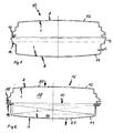
- FIG. 1 a housing part 10 is shown in section.
- the housing entire part 10 is in a mold cavity mold (not shown) made in one piece as a large hollow part, wherein it has a wall thickness s.
- the wall thickness s is almost constant in the housing entire part 10, wherein it extends between an outer side A and an inner side I.
- the entire housing part 10 has an area which forms the lower housing part 11. Another area forms the upper housing part 12.
- the two housing parts 11, 12 are connected along the dash-dotted line with a waste piece 13.
- the geometries of the housing parts 11, 12 are designed such that they can mesh with each other after the removal of the waste piece 13 and sealingly connected to each other.
- the lower housing part 11 on an insert 14, which is geometrically formed by the outer side A of the lower housing part 11.
- the upper housing part 12 has a receptacle 15, which after removing the waste piece 13 receives the insert 14.
- the receptacle 15 is geometrically formed by the inner side I of the upper housing part 12.
- FIG. 2 a filter housing 16 is shown in section. Of the FIG. 1 corresponding components are provided with the same reference numerals.
- the filter housing 16 has the upper housing part 12 and the lower housing part 11.
- a filter element 17 is introduced in the lower housing part 11.
- the filter element 17 is sealingly introduced between the lower housing part 11 and the upper housing part 12, whereby a raw area 18 is separated from a clean area 19.
- the raw area 18 is arranged in the upper housing part 12, this having an inlet 20, which was introduced by mechanical processing in the upper housing part 12 has.
- the clean area 19 is arranged in the lower housing part 11, wherein the lower housing part 11 has an outlet 21, which was also produced by a mechanical processing of the lower housing part 11.
- the inlet 20 or outlet 21 can of course also be formed by a special geometry of the mold cavity mold during the production of the housing part.
- the fluid to be cleaned flows in the direction of the arrow through the inlet 20 into the filter housing 16, is cleaned by the filter element 17 and then flows out through the outlet 21, also in the direction of arrow, from the filter housing 16 again.
- FIG. 3 is a double-walled upper housing part 12 'shown in section.
- the outer side A is designed such that it encloses the inner side I on all sides.
- the upper housing part 12 'on all sides over a, by the mold cavity form geometrically defined outside A, which has low tolerances. Due to these small tolerances, the insert 14 'is geometrically defined exactly and is not subject to the wall thickness fluctuations of the housing part 12'.
- the inner side I encloses a closed inner volume 22, which is not flowed through.
- This interior volume 22 has acoustic properties that can dampen the intake noise of an internal combustion engine.
- this upper housing part 12 'by its double-walled design has a higher rigidity.
- FIG. 4 the lower housing part 11 'is shown, which is also double-walled.
- corresponding components are provided with the same reference numerals, the comments on the outside A, inside I and inner volume 22 also apply to the lower housing part 11 '.
- the receptacle 15 ' is, as the insert 14' according to FIG. 3 completely formed by the outside A.
- the receptacle 15 ' has an exactly geometrically defined contour.
- a filter element (not shown) can be used and fixed by the insert 14' of the upper housing part 12 '.
Landscapes
- Engineering & Computer Science (AREA)
- Mechanical Engineering (AREA)
- Chemical & Material Sciences (AREA)
- Chemical Kinetics & Catalysis (AREA)
- Combustion & Propulsion (AREA)
- General Engineering & Computer Science (AREA)
- Filtering Of Dispersed Particles In Gases (AREA)
- Filtering Materials (AREA)
- Moulding By Coating Moulds (AREA)
- Glass Compositions (AREA)
Claims (4)
- Procédé de fabrication d'un boîtier de filtre avec élément filtrant (17) se composant au moins des opérations suivantes: remplissage de poudre de matière plastique dans un moule creux d'outil, le moule creux d'outil correspondant à la partie de boîtier à fabriquer, chauffage du moule creux d'outil, rotation du moule creux d'outil autour des axes équatorial et polaire, refroidissement et ouverture du moule creux d'outil et démoulage de la partie de boîtier (11, 12), les deux parties de boîtier (12) et (11) étant reliées l'une à l'autre, la face extérieure (A) d'au moins une partie de boîtier (11, 12) étant reliée à la face extérieure ou la face intérieure (A), (I) de l'autre partie de boîtier (11, 12), caractérisé en ce que les deux parties de boîtier (11, 12) sont fabriquées en un bloc et en une seule opération, le refroidissement étant réalisé de manière à ce que la partie soit refroidie de façon uniforme et soit divisée en deux ou plusieurs parties après le démoulage, les parties de boîtier (11, 12) étant ainsi formées, puis les parties de boîtier (11, 12) étant reliées l'une à l'autre, de sorte que l'élément filtrant (17) soit mis en place de manière étanche entre la partie inférieure de boîtier (11) et la partie supérieure de boîtier (12) et qu'ainsi, une zone non-filtrée (18) soit séparée d'une zone filtrée (19).
- Procédé selon la revendication 1, caractérisé en ce qu'une pièce de rebut (13) est extraite d'entre les parties de boîtier (11, 12).
- Procédé selon l'une des revendications précédentes, caractérisé en ce que la poudre de matière plastique utilisée est un polyéthylène ou un polypropylène.
- Procédé selon l'une des revendications précédentes, caractérisé en ce que les parties de boîtier (11, 12) sont reliées les unes aux autres au moyen de crochets, de vis ou d'autres éléments.
Applications Claiming Priority (2)
| Application Number | Priority Date | Filing Date | Title |
|---|---|---|---|
| DE10360230A DE10360230A1 (de) | 2003-12-20 | 2003-12-20 | Herstellverfahren für Filtergehäuse |
| PCT/EP2004/053600 WO2005061880A1 (fr) | 2003-12-20 | 2004-12-20 | Boitier de filtre et procede de realisation |
Publications (2)
| Publication Number | Publication Date |
|---|---|
| EP1702154A1 EP1702154A1 (fr) | 2006-09-20 |
| EP1702154B1 true EP1702154B1 (fr) | 2011-03-23 |
Family
ID=34683703
Family Applications (1)
| Application Number | Title | Priority Date | Filing Date |
|---|---|---|---|
| EP04804936A Expired - Lifetime EP1702154B1 (fr) | 2003-12-20 | 2004-12-20 | Boitier de filtre et procede de realisation |
Country Status (7)
| Country | Link |
|---|---|
| US (1) | US20080157420A1 (fr) |
| EP (1) | EP1702154B1 (fr) |
| JP (1) | JP2007515587A (fr) |
| AT (1) | ATE503103T1 (fr) |
| BR (1) | BRPI0417835A (fr) |
| DE (2) | DE10360230A1 (fr) |
| WO (1) | WO2005061880A1 (fr) |
Families Citing this family (4)
| Publication number | Priority date | Publication date | Assignee | Title |
|---|---|---|---|---|
| DE202007018599U1 (de) * | 2007-12-17 | 2009-01-08 | Carl Freudenberg Kg | Filtergehäuse für ein stationäres Aggregat |
| DK3250475T3 (da) * | 2015-01-27 | 2019-12-09 | Airopack Tech Group B V | Trykstyresystem |
| WO2022036356A1 (fr) | 2020-08-10 | 2022-02-17 | Vayu Global Health Innovations, LLC | Boîtier de filtre à gaz avec support de filtre à gaz remplaçable pour systèmes de ventilation médicale |
| US12479708B2 (en) | 2020-09-24 | 2025-11-25 | John A. Eisler | Lift system for contaminant mitigation |
Family Cites Families (12)
| Publication number | Priority date | Publication date | Assignee | Title |
|---|---|---|---|---|
| NL6706661A (fr) * | 1966-05-26 | 1967-11-27 | ||
| SE359749B (fr) * | 1972-01-26 | 1973-09-10 | Flodin B | |
| US4292015A (en) * | 1979-03-12 | 1981-09-29 | Michael Hritz | Apparatus for rotational molding |
| DE4141823C2 (de) * | 1991-12-18 | 1994-12-15 | Mann & Hummel Filter | Flüssigkeitsfilter |
| DE4218396B4 (de) * | 1992-06-04 | 2004-04-01 | Mann + Hummel Gmbh | Filtereinrichtung, insbesondere zum Filtrieren der Ansaugluft eines Verbrennungsmotors |
| AUPM399094A0 (en) * | 1994-02-18 | 1994-03-17 | Automated Plastic Systems Pty Ltd | Automatic rotamoulding apparatus and method of control |
| DE19539463B4 (de) * | 1995-02-08 | 2005-07-14 | Mann + Hummel Gmbh | Gehäuse, insbesondere für ein Luftfilter für die Ansaugluft einer Brennkraftmaschine |
| DE19529400C2 (de) | 1995-08-10 | 1997-05-15 | Funken & Co Gmbh | Verfahren zur Herstellung eines Dachventilatorgehäuses |
| GB9619126D0 (en) * | 1996-09-13 | 1996-10-23 | Rotational Mouldings Ltd | Acoustic hood |
| JPH1174337A (ja) * | 1997-08-28 | 1999-03-16 | Nippon Zeon Co Ltd | 熱可塑性樹脂製容器 |
| US20030090024A1 (en) * | 2001-11-14 | 2003-05-15 | Rubbermaid Incorporated | Method and apparatus for separating molded articles |
| US6692347B1 (en) * | 2002-09-27 | 2004-02-17 | L&L Products, Inc. | Filter housing assembly for transportation vehicles |
-
2003
- 2003-12-20 DE DE10360230A patent/DE10360230A1/de not_active Withdrawn
-
2004
- 2004-12-20 AT AT04804936T patent/ATE503103T1/de active
- 2004-12-20 JP JP2006544459A patent/JP2007515587A/ja active Pending
- 2004-12-20 WO PCT/EP2004/053600 patent/WO2005061880A1/fr not_active Ceased
- 2004-12-20 EP EP04804936A patent/EP1702154B1/fr not_active Expired - Lifetime
- 2004-12-20 DE DE502004012337T patent/DE502004012337D1/de not_active Expired - Lifetime
- 2004-12-20 BR BRPI0417835-1A patent/BRPI0417835A/pt not_active IP Right Cessation
-
2007
- 2007-06-21 US US11/766,554 patent/US20080157420A1/en not_active Abandoned
Also Published As
| Publication number | Publication date |
|---|---|
| DE502004012337D1 (de) | 2011-05-05 |
| BRPI0417835A (pt) | 2007-04-10 |
| DE10360230A1 (de) | 2005-07-21 |
| US20080157420A1 (en) | 2008-07-03 |
| EP1702154A1 (fr) | 2006-09-20 |
| JP2007515587A (ja) | 2007-06-14 |
| WO2005061880A1 (fr) | 2005-07-07 |
| ATE503103T1 (de) | 2011-04-15 |
Similar Documents
| Publication | Publication Date | Title |
|---|---|---|
| EP2507083B1 (fr) | Elément filtrant et procédé de fabrication d'un élément filtrant | |
| DE10058478B4 (de) | Flaches Filterelement mit angegossenem Rahmen | |
| EP0726389B1 (fr) | Carter d'un filtre à air pour moteur à combustion interne | |
| EP0824950A1 (fr) | Elément filtrant et procédé pour sa production | |
| DE2620816A1 (de) | Kunststoff-formkoerper und verfahren zu seiner herstellung | |
| EP2296776B1 (fr) | Adaptateur de fixation d'un élément filtrant | |
| EP2334399B1 (fr) | Procédé de fabrication d'un disque terminal de filtre et d'un filtre à fluide, disque terminal de filtre | |
| EP1527867B1 (fr) | Procédé de fabrication d'une roue ventilateur et roue ventilateur selon ce procédé | |
| EP1702154B1 (fr) | Boitier de filtre et procede de realisation | |
| DE102011111366A1 (de) | Filterelement und Verfahren zu dessen Herstellung | |
| DE69504532T2 (de) | Verfahren und vorrichtung zum ummanteln von glassscheibenkanten mit einer polyurethandichtung | |
| DE1729108A1 (de) | Verfahren zum Herstellen von geschlossenen und offenen Behaeltern und Formteilen ausKunststoffen und auf diese Weise hergestellte Behaelter und Formteile | |
| EP3009250B1 (fr) | Outil de moulage par injection en plastique destine a fabriquer un composant de moulage par multi-injection de plusieurs composants | |
| EP1204516A1 (fr) | Procede de realisation d'un corps creux par la technique de moulage a noyau fusible | |
| EP0767309B1 (fr) | Procédé de fabrication d'un boítier pour un ventilateur de toit | |
| DE102013222362A1 (de) | Verrfahren zur Herstellung eines Kunststoffbauteils | |
| DE102015218142A1 (de) | Verfahren zur Herstellung eines Verbundbauteils | |
| WO1994006613A1 (fr) | Procede de fabrication d'une buse | |
| DE19518124C1 (de) | Vorrichtung zur Erzeugung von Formteilen aus thermoplastischem Kunststoff | |
| DE10315913A1 (de) | Hohlkörper aus Metall mit einer Innenauskleidung aus synthetischem Material und Vorrichtung zu deren Ausführung | |
| WO2004090455A1 (fr) | Reservoir accumulateur, echangeur thermique et procede pour realiser un reservoir accumulateur | |
| DE102006009344B4 (de) | Verfahren zur Herstellung einer Baueinheit aus mittels eines Filmscharniers miteinander verbundenen Profilformteilen | |
| WO2002014046A1 (fr) | Composant presentant une fonction de joint, en particulier de joint creux profile, et procede de fabrication | |
| DE102017128333B3 (de) | Adapter und Verfahren zur Herstellung eines Behälters unter Verwendung des Adapters sowie Behälter mit dem Adapter | |
| DE10221478A1 (de) | Formvorrichtung zum Herstellen von Kunststoffformhäuten |
Legal Events
| Date | Code | Title | Description |
|---|---|---|---|
| PUAI | Public reference made under article 153(3) epc to a published international application that has entered the european phase |
Free format text: ORIGINAL CODE: 0009012 |
|
| 17P | Request for examination filed |
Effective date: 20060612 |
|
| AK | Designated contracting states |
Kind code of ref document: A1 Designated state(s): AT BE BG CH CY CZ DE DK EE ES FI FR GB GR HU IE IS IT LI LT LU MC NL PL PT RO SE SI SK TR |
|
| 17Q | First examination report despatched |
Effective date: 20061204 |
|
| DAX | Request for extension of the european patent (deleted) | ||
| GRAP | Despatch of communication of intention to grant a patent |
Free format text: ORIGINAL CODE: EPIDOSNIGR1 |
|
| GRAS | Grant fee paid |
Free format text: ORIGINAL CODE: EPIDOSNIGR3 |
|
| GRAA | (expected) grant |
Free format text: ORIGINAL CODE: 0009210 |
|
| AK | Designated contracting states |
Kind code of ref document: B1 Designated state(s): AT BE BG CH CY CZ DE DK EE ES FI FR GB GR HU IE IS IT LI LT LU MC NL PL PT RO SE SI SK TR |
|
| REG | Reference to a national code |
Ref country code: GB Ref legal event code: FG4D Free format text: NOT ENGLISH |
|
| REG | Reference to a national code |
Ref country code: CH Ref legal event code: EP |
|
| REG | Reference to a national code |
Ref country code: IE Ref legal event code: FG4D |
|
| REF | Corresponds to: |
Ref document number: 502004012337 Country of ref document: DE Date of ref document: 20110505 Kind code of ref document: P |
|
| REG | Reference to a national code |
Ref country code: DE Ref legal event code: R096 Ref document number: 502004012337 Country of ref document: DE Effective date: 20110505 |
|
| REG | Reference to a national code |
Ref country code: NL Ref legal event code: VDEP Effective date: 20110323 |
|
| PG25 | Lapsed in a contracting state [announced via postgrant information from national office to epo] |
Ref country code: SE Free format text: LAPSE BECAUSE OF FAILURE TO SUBMIT A TRANSLATION OF THE DESCRIPTION OR TO PAY THE FEE WITHIN THE PRESCRIBED TIME-LIMIT Effective date: 20110323 Ref country code: LT Free format text: LAPSE BECAUSE OF FAILURE TO SUBMIT A TRANSLATION OF THE DESCRIPTION OR TO PAY THE FEE WITHIN THE PRESCRIBED TIME-LIMIT Effective date: 20110323 Ref country code: GR Free format text: LAPSE BECAUSE OF FAILURE TO SUBMIT A TRANSLATION OF THE DESCRIPTION OR TO PAY THE FEE WITHIN THE PRESCRIBED TIME-LIMIT Effective date: 20110624 |
|
| LTIE | Lt: invalidation of european patent or patent extension |
Effective date: 20110323 |
|
| PG25 | Lapsed in a contracting state [announced via postgrant information from national office to epo] |
Ref country code: CY Free format text: LAPSE BECAUSE OF FAILURE TO SUBMIT A TRANSLATION OF THE DESCRIPTION OR TO PAY THE FEE WITHIN THE PRESCRIBED TIME-LIMIT Effective date: 20110323 Ref country code: SI Free format text: LAPSE BECAUSE OF FAILURE TO SUBMIT A TRANSLATION OF THE DESCRIPTION OR TO PAY THE FEE WITHIN THE PRESCRIBED TIME-LIMIT Effective date: 20110323 Ref country code: FI Free format text: LAPSE BECAUSE OF FAILURE TO SUBMIT A TRANSLATION OF THE DESCRIPTION OR TO PAY THE FEE WITHIN THE PRESCRIBED TIME-LIMIT Effective date: 20110323 Ref country code: BG Free format text: LAPSE BECAUSE OF FAILURE TO SUBMIT A TRANSLATION OF THE DESCRIPTION OR TO PAY THE FEE WITHIN THE PRESCRIBED TIME-LIMIT Effective date: 20110623 |
|
| REG | Reference to a national code |
Ref country code: IE Ref legal event code: FD4D |
|
| PG25 | Lapsed in a contracting state [announced via postgrant information from national office to epo] |
Ref country code: EE Free format text: LAPSE BECAUSE OF FAILURE TO SUBMIT A TRANSLATION OF THE DESCRIPTION OR TO PAY THE FEE WITHIN THE PRESCRIBED TIME-LIMIT Effective date: 20110323 Ref country code: PT Free format text: LAPSE BECAUSE OF FAILURE TO SUBMIT A TRANSLATION OF THE DESCRIPTION OR TO PAY THE FEE WITHIN THE PRESCRIBED TIME-LIMIT Effective date: 20110725 |
|
| PG25 | Lapsed in a contracting state [announced via postgrant information from national office to epo] |
Ref country code: SK Free format text: LAPSE BECAUSE OF FAILURE TO SUBMIT A TRANSLATION OF THE DESCRIPTION OR TO PAY THE FEE WITHIN THE PRESCRIBED TIME-LIMIT Effective date: 20110323 Ref country code: CZ Free format text: LAPSE BECAUSE OF FAILURE TO SUBMIT A TRANSLATION OF THE DESCRIPTION OR TO PAY THE FEE WITHIN THE PRESCRIBED TIME-LIMIT Effective date: 20110323 Ref country code: IS Free format text: LAPSE BECAUSE OF FAILURE TO SUBMIT A TRANSLATION OF THE DESCRIPTION OR TO PAY THE FEE WITHIN THE PRESCRIBED TIME-LIMIT Effective date: 20110723 Ref country code: RO Free format text: LAPSE BECAUSE OF FAILURE TO SUBMIT A TRANSLATION OF THE DESCRIPTION OR TO PAY THE FEE WITHIN THE PRESCRIBED TIME-LIMIT Effective date: 20110323 Ref country code: ES Free format text: LAPSE BECAUSE OF FAILURE TO SUBMIT A TRANSLATION OF THE DESCRIPTION OR TO PAY THE FEE WITHIN THE PRESCRIBED TIME-LIMIT Effective date: 20110704 |
|
| PG25 | Lapsed in a contracting state [announced via postgrant information from national office to epo] |
Ref country code: NL Free format text: LAPSE BECAUSE OF FAILURE TO SUBMIT A TRANSLATION OF THE DESCRIPTION OR TO PAY THE FEE WITHIN THE PRESCRIBED TIME-LIMIT Effective date: 20110323 |
|
| PLBE | No opposition filed within time limit |
Free format text: ORIGINAL CODE: 0009261 |
|
| STAA | Information on the status of an ep patent application or granted ep patent |
Free format text: STATUS: NO OPPOSITION FILED WITHIN TIME LIMIT |
|
| PG25 | Lapsed in a contracting state [announced via postgrant information from national office to epo] |
Ref country code: IE Free format text: LAPSE BECAUSE OF FAILURE TO SUBMIT A TRANSLATION OF THE DESCRIPTION OR TO PAY THE FEE WITHIN THE PRESCRIBED TIME-LIMIT Effective date: 20110323 |
|
| 26N | No opposition filed |
Effective date: 20111227 |
|
| PG25 | Lapsed in a contracting state [announced via postgrant information from national office to epo] |
Ref country code: DK Free format text: LAPSE BECAUSE OF FAILURE TO SUBMIT A TRANSLATION OF THE DESCRIPTION OR TO PAY THE FEE WITHIN THE PRESCRIBED TIME-LIMIT Effective date: 20110323 Ref country code: PL Free format text: LAPSE BECAUSE OF FAILURE TO SUBMIT A TRANSLATION OF THE DESCRIPTION OR TO PAY THE FEE WITHIN THE PRESCRIBED TIME-LIMIT Effective date: 20110323 |
|
| REG | Reference to a national code |
Ref country code: DE Ref legal event code: R097 Ref document number: 502004012337 Country of ref document: DE Effective date: 20111227 |
|
| PG25 | Lapsed in a contracting state [announced via postgrant information from national office to epo] |
Ref country code: IT Free format text: LAPSE BECAUSE OF FAILURE TO SUBMIT A TRANSLATION OF THE DESCRIPTION OR TO PAY THE FEE WITHIN THE PRESCRIBED TIME-LIMIT Effective date: 20110323 |
|
| BERE | Be: lapsed |
Owner name: MANN + HUMMEL G.M.B.H. Effective date: 20111231 |
|
| PG25 | Lapsed in a contracting state [announced via postgrant information from national office to epo] |
Ref country code: MC Free format text: LAPSE BECAUSE OF NON-PAYMENT OF DUE FEES Effective date: 20111231 |
|
| REG | Reference to a national code |
Ref country code: CH Ref legal event code: PL |
|
| GBPC | Gb: european patent ceased through non-payment of renewal fee |
Effective date: 20111220 |
|
| REG | Reference to a national code |
Ref country code: FR Ref legal event code: ST Effective date: 20120831 |
|
| PG25 | Lapsed in a contracting state [announced via postgrant information from national office to epo] |
Ref country code: GB Free format text: LAPSE BECAUSE OF NON-PAYMENT OF DUE FEES Effective date: 20111220 Ref country code: CH Free format text: LAPSE BECAUSE OF NON-PAYMENT OF DUE FEES Effective date: 20111231 Ref country code: LI Free format text: LAPSE BECAUSE OF NON-PAYMENT OF DUE FEES Effective date: 20111231 Ref country code: BE Free format text: LAPSE BECAUSE OF NON-PAYMENT OF DUE FEES Effective date: 20111231 |
|
| REG | Reference to a national code |
Ref country code: AT Ref legal event code: MM01 Ref document number: 503103 Country of ref document: AT Kind code of ref document: T Effective date: 20111220 |
|
| PG25 | Lapsed in a contracting state [announced via postgrant information from national office to epo] |
Ref country code: FR Free format text: LAPSE BECAUSE OF NON-PAYMENT OF DUE FEES Effective date: 20120102 |
|
| PG25 | Lapsed in a contracting state [announced via postgrant information from national office to epo] |
Ref country code: LU Free format text: LAPSE BECAUSE OF NON-PAYMENT OF DUE FEES Effective date: 20111220 |
|
| PG25 | Lapsed in a contracting state [announced via postgrant information from national office to epo] |
Ref country code: AT Free format text: LAPSE BECAUSE OF NON-PAYMENT OF DUE FEES Effective date: 20111220 |
|
| PG25 | Lapsed in a contracting state [announced via postgrant information from national office to epo] |
Ref country code: TR Free format text: LAPSE BECAUSE OF FAILURE TO SUBMIT A TRANSLATION OF THE DESCRIPTION OR TO PAY THE FEE WITHIN THE PRESCRIBED TIME-LIMIT Effective date: 20110323 |
|
| PG25 | Lapsed in a contracting state [announced via postgrant information from national office to epo] |
Ref country code: HU Free format text: LAPSE BECAUSE OF FAILURE TO SUBMIT A TRANSLATION OF THE DESCRIPTION OR TO PAY THE FEE WITHIN THE PRESCRIBED TIME-LIMIT Effective date: 20110323 |
|
| PGFP | Annual fee paid to national office [announced via postgrant information from national office to epo] |
Ref country code: DE Payment date: 20141211 Year of fee payment: 11 |
|
| REG | Reference to a national code |
Ref country code: DE Ref legal event code: R119 Ref document number: 502004012337 Country of ref document: DE |
|
| PG25 | Lapsed in a contracting state [announced via postgrant information from national office to epo] |
Ref country code: DE Free format text: LAPSE BECAUSE OF NON-PAYMENT OF DUE FEES Effective date: 20160701 |