EP1702155B1 - Procede pour optimiser l'avance a l'injection de carburant dans un moteur de locomotive - Google Patents
Procede pour optimiser l'avance a l'injection de carburant dans un moteur de locomotive Download PDFInfo
- Publication number
- EP1702155B1 EP1702155B1 EP04800619.1A EP04800619A EP1702155B1 EP 1702155 B1 EP1702155 B1 EP 1702155B1 EP 04800619 A EP04800619 A EP 04800619A EP 1702155 B1 EP1702155 B1 EP 1702155B1
- Authority
- EP
- European Patent Office
- Prior art keywords
- helix
- plunger
- notch
- emissions
- idle
- Prior art date
- Legal status (The legal status is an assumption and is not a legal conclusion. Google has not performed a legal analysis and makes no representation as to the accuracy of the status listed.)
- Expired - Lifetime
Links
- 239000000446 fuel Substances 0.000 title claims description 71
- 238000002347 injection Methods 0.000 title claims description 49
- 239000007924 injection Substances 0.000 title claims description 49
- 238000000034 method Methods 0.000 title claims description 13
- 230000003137 locomotive effect Effects 0.000 title description 25
- 238000002485 combustion reaction Methods 0.000 claims description 18
- 238000004519 manufacturing process Methods 0.000 claims description 5
- 230000007246 mechanism Effects 0.000 claims description 4
- 229910002089 NOx Inorganic materials 0.000 description 43
- 230000008859 change Effects 0.000 description 10
- 230000009467 reduction Effects 0.000 description 8
- 230000000979 retarding effect Effects 0.000 description 8
- 238000002474 experimental method Methods 0.000 description 7
- 230000007704 transition Effects 0.000 description 7
- 229910000831 Steel Inorganic materials 0.000 description 6
- 239000010959 steel Substances 0.000 description 6
- 238000013461 design Methods 0.000 description 5
- 229930195733 hydrocarbon Natural products 0.000 description 5
- 150000002430 hydrocarbons Chemical class 0.000 description 5
- VYZAMTAEIAYCRO-UHFFFAOYSA-N Chromium Chemical compound [Cr] VYZAMTAEIAYCRO-UHFFFAOYSA-N 0.000 description 4
- MWUXSHHQAYIFBG-UHFFFAOYSA-N Nitric oxide Chemical compound O=[N] MWUXSHHQAYIFBG-UHFFFAOYSA-N 0.000 description 4
- 239000011651 chromium Substances 0.000 description 4
- 238000012360 testing method Methods 0.000 description 4
- MGWGWNFMUOTEHG-UHFFFAOYSA-N 4-(3,5-dimethylphenyl)-1,3-thiazol-2-amine Chemical compound CC1=CC(C)=CC(C=2N=C(N)SC=2)=C1 MGWGWNFMUOTEHG-UHFFFAOYSA-N 0.000 description 3
- CURLTUGMZLYLDI-UHFFFAOYSA-N Carbon dioxide Chemical compound O=C=O CURLTUGMZLYLDI-UHFFFAOYSA-N 0.000 description 3
- 229910052804 chromium Inorganic materials 0.000 description 3
- 230000007613 environmental effect Effects 0.000 description 3
- 238000003754 machining Methods 0.000 description 3
- JCXJVPUVTGWSNB-UHFFFAOYSA-N nitrogen dioxide Inorganic materials O=[N]=O JCXJVPUVTGWSNB-UHFFFAOYSA-N 0.000 description 3
- 239000007921 spray Substances 0.000 description 3
- IJGRMHOSHXDMSA-UHFFFAOYSA-N Atomic nitrogen Chemical compound N#N IJGRMHOSHXDMSA-UHFFFAOYSA-N 0.000 description 2
- 239000004215 Carbon black (E152) Substances 0.000 description 2
- UGFAIRIUMAVXCW-UHFFFAOYSA-N Carbon monoxide Chemical compound [O+]#[C-] UGFAIRIUMAVXCW-UHFFFAOYSA-N 0.000 description 2
- XEEYBQQBJWHFJM-UHFFFAOYSA-N Iron Chemical compound [Fe] XEEYBQQBJWHFJM-UHFFFAOYSA-N 0.000 description 2
- 230000001174 ascending effect Effects 0.000 description 2
- 238000000889 atomisation Methods 0.000 description 2
- 230000008901 benefit Effects 0.000 description 2
- 229910002092 carbon dioxide Inorganic materials 0.000 description 2
- 239000001569 carbon dioxide Substances 0.000 description 2
- 229910002091 carbon monoxide Inorganic materials 0.000 description 2
- 150000001875 compounds Chemical class 0.000 description 2
- 230000001186 cumulative effect Effects 0.000 description 2
- 230000003247 decreasing effect Effects 0.000 description 2
- 239000000463 material Substances 0.000 description 2
- 230000008569 process Effects 0.000 description 2
- 229910000851 Alloy steel Inorganic materials 0.000 description 1
- 229910000599 Cr alloy Inorganic materials 0.000 description 1
- 229910000990 Ni alloy Inorganic materials 0.000 description 1
- ODUCDPQEXGNKDN-UHFFFAOYSA-N Nitrogen oxide(NO) Natural products O=N ODUCDPQEXGNKDN-UHFFFAOYSA-N 0.000 description 1
- 238000003916 acid precipitation Methods 0.000 description 1
- 238000013459 approach Methods 0.000 description 1
- 230000000295 complement effect Effects 0.000 description 1
- 239000000470 constituent Substances 0.000 description 1
- 230000001955 cumulated effect Effects 0.000 description 1
- 230000003111 delayed effect Effects 0.000 description 1
- 230000006866 deterioration Effects 0.000 description 1
- 230000001627 detrimental effect Effects 0.000 description 1
- 238000005553 drilling Methods 0.000 description 1
- 230000000694 effects Effects 0.000 description 1
- 238000005516 engineering process Methods 0.000 description 1
- 230000006870 function Effects 0.000 description 1
- 239000007789 gas Substances 0.000 description 1
- 230000006872 improvement Effects 0.000 description 1
- 229910052742 iron Inorganic materials 0.000 description 1
- 238000005259 measurement Methods 0.000 description 1
- 229910052751 metal Inorganic materials 0.000 description 1
- 239000002184 metal Substances 0.000 description 1
- 150000002739 metals Chemical class 0.000 description 1
- 238000012986 modification Methods 0.000 description 1
- 230000004048 modification Effects 0.000 description 1
- 229910052757 nitrogen Inorganic materials 0.000 description 1
- 239000003129 oil well Substances 0.000 description 1
- 238000005457 optimization Methods 0.000 description 1
- 239000013618 particulate matter Substances 0.000 description 1
- 230000037361 pathway Effects 0.000 description 1
- 238000010248 power generation Methods 0.000 description 1
- 238000005086 pumping Methods 0.000 description 1
- 230000001105 regulatory effect Effects 0.000 description 1
- 230000002459 sustained effect Effects 0.000 description 1
Images


Classifications
-
- F—MECHANICAL ENGINEERING; LIGHTING; HEATING; WEAPONS; BLASTING
- F02—COMBUSTION ENGINES; HOT-GAS OR COMBUSTION-PRODUCT ENGINE PLANTS
- F02M—SUPPLYING COMBUSTION ENGINES IN GENERAL WITH COMBUSTIBLE MIXTURES OR CONSTITUENTS THEREOF
- F02M59/00—Pumps specially adapted for fuel-injection and not provided for in groups F02M39/00 -F02M57/00, e.g. rotary cylinder-block type of pumps
- F02M59/20—Varying fuel delivery in quantity or timing
- F02M59/24—Varying fuel delivery in quantity or timing with constant-length-stroke pistons having variable effective portion of stroke
- F02M59/26—Varying fuel delivery in quantity or timing with constant-length-stroke pistons having variable effective portion of stroke caused by movements of pistons relative to their cylinders
- F02M59/265—Varying fuel delivery in quantity or timing with constant-length-stroke pistons having variable effective portion of stroke caused by movements of pistons relative to their cylinders characterised by the arrangement or form of spill port of spill contour on the piston
-
- F—MECHANICAL ENGINEERING; LIGHTING; HEATING; WEAPONS; BLASTING
- F02—COMBUSTION ENGINES; HOT-GAS OR COMBUSTION-PRODUCT ENGINE PLANTS
- F02M—SUPPLYING COMBUSTION ENGINES IN GENERAL WITH COMBUSTIBLE MIXTURES OR CONSTITUENTS THEREOF
- F02M57/00—Fuel-injectors combined or associated with other devices
- F02M57/02—Injectors structurally combined with fuel-injection pumps
- F02M57/022—Injectors structurally combined with fuel-injection pumps characterised by the pump drive
- F02M57/023—Injectors structurally combined with fuel-injection pumps characterised by the pump drive mechanical
Definitions
- Embodiments of the present invention relate to methods for reducing engine emissions in a diesel engine, such as a locomotive diesel engine.
- Exhaust from a locomotive diesel engine includes various gaseous constituents, such as NO x , carbon monoxide (CO), carbon dioxide (CO 2 ), and hydrocarbons (HC), as well as particulate matter. Severe environmental and economic consequences may ensure if locomotive engine emissions do not comply with applicable EPA standards.
- U.S. Patent No. 6,470,844 to Biess et al. discloses a system and method that automatically shuts down a primary engine of a locomotive after the primary engine has been idling for a predetermined period of time. A small secondary engine is started to perform useful functions on behalf of the shut-down primary engine. Because it reduces locomotive idle time, this approach reduces engine emissions. However, engine emissions remain a cause for concern, when the primary engine is running.
- PCT Publication No. WO 81/01314 to Henson, et al discloses, in fuel injector types including a rotating plunger having a double helix and control edge, a control edge configuration which improves the starting characteristics of certain internal combustion engines.
- a starting groove and a starting projection are provided in the control edges which simultaneously greatly increase the amount of fuel injected into the combustion space and retard engine timing. Further disclosed therein is a control mechanism which prevents the injectors from accidentally or intentionally rotating to the start position when the engine is running. A similar system is disclosed in US 35 66 849 . Therefore, what is needed is a method for reducing engine emissions in a locomotive. Accordingly, the present invention a method of manufacturing a fuel injector as set out in claim 1.
- FIG. 12 is a graph illustrating an experiment that compares another switcher helix (switcher helix 2) and a standard helix for a switcher engine that had the timing thereof retarded for notches N6 down through the idle positions.
- FIG. 13 is a graph illustrating NOx emissions profile for the experiment shown in FIG. 12 .
- FIG. 14 is a graph illustrating an experiment in which a switcher helix (switcher helix 2) was uniformly retarded by changing the fly-wheel pointer position.
- FIG. 15 is a graph illustrating NOx emissions profile for the experiment shown in FIG. 14 .
- FIG. 16 is a graph illustrating NOx emissions profile in gms/hr for a line-haul locomotive engine employing a prior art unit injector.
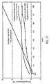
- FIG. 17 is a graph illustrating helix performance for a line-haul locomotive engine.
- FIG. 18 is a graph illustrating NOx emissions profile in gms/hr for a line-haul locomotive engine.
- a fuel injection mechanism includes a fuel injector (unit injector) or fuel injection pump.
- the fuel injector or fuel injection pump includes a plunger with an upper helix whose angle changes between points on the plunger that correspond to an idle throttle position and a full throttle position. As such, injection timing is optimized, and engine emissions are reduced.
- the fuel injection mechanism employs a nozzle tip formed of a chromium hot-work steel. Accordingly, reductions in engine emissions may be sustained over long periods of time.
- FIG. 1 is a partially broken away cross-sectional view of a fuel injector 100 made according to the present invention.
- injector 100 may be a unit injector for a fuel system of an engine, such as a diesel engine manufactured by GM EMD (General Motors Electro-motive Division).
- EMD-type engines employ mechanical control of injection timing and may be implemented effectively in various settings, such as, for example, locomotive (line-haul, switcher, passenger, or road), marine propulsion, offshore- and land-based oil well drilling rigs, stationary electric power generation, nuclear power generating plants, and pipeline and dredge pump applications.
- injector 100 is implemented in an EMD 567, 645, or 710 series engine.
- drawings herein depict a unit injector and associated plungers for EMD-type engines.
- teachings herein may be similarly applied to engines that employ fuel injection pumps, such as diesel engines manufactured by GE Transportation Systems, including the GE 7FDL and 7HDL engines, and diesel engines manufactured by ALCO.
- each fuel injection pump includes a plunger that supplies fuel to an injector via a high pressure fuel line.
- Helices of such plungers may be modified consistent with principles presented herein.
- a nozzle tip as described herein also may be utilized.
- Fuel injector 100 includes a body 150, a plunger 110, a housing nut 115, a bushing 120, a nozzle tip 130, and spray holes 140. Other components of injector 100 are not shown in FIG. 1 and are known in the art. Injector 100 is located and seated in a hole of a cylinder head of an engine fuel system.
- nozzle tip 130 of injector 100 may be formed of a chromium hot-work steel.
- the steel may be substantially through-hardened, and may conform, for example, to the H11 specification of the American Iron and Steel Institute (AISI) or the T20811 specification of the Unified Numbering System (UNS).
- AISI American Iron and Steel Institute
- UNS Unified Numbering System
- nozzle tip 130 may create effective atomization for longer periods of time, without deterioration of spray holes 140. Accordingly, injector 100 may have an extended life of use in an injection system.
- Bushing 120 includes an upper port 160 and a lower port 170.
- Upper port 160 and lower port 170 are pathways for fuel. The amount of fuel injected into a cylinder depends on the extent to which the ports are closed, as described below.
- plunger 110 may vary depending on the implementation. Diameters of plungers may vary depending on the amount of fuel that is needed for injection. In an exemplary implementation, plunger 110 may have a diameter of between about 8 and 22 mm. Materials for plunger 110 may be chosen to prevent plunger 110 from substantially wearing down over time, and thus to prevent performance of plunger 110 from being degraded. Plunger 110 may be formed, for example, of bearing quality or high alloy steel, such as a chromium/nickel alloy. For example, the steel may conform to the 51501 or 52100 specifications of the Society of Automotive Engineers (SAE). Use of appropriate metals may ensure that helices described below maintain their shape for longer periods of time.
- SAE Society of Automotive Engineers
- Plunger 110 includes an upper helix 180 and a lower helix 190.
- Upper helix 180 and lower helix 190 determine the opening and closing of upper port 160 and lower port 170 of bushing 120.
- Upper helix 180 determines when injection starts, and lower helix 190 determines when injection ends. As such, the helices determine the volume of fuel that is injected.
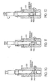
- Figs. 1B-1F illustrate a complete stroke of the plunger 110 with respect to bushing 120 for a switcher-type engine.
- the upper and lower ports 160, 170 open to admit fuel as shown in Fig. 1B .
- fuel escapes through the upper port 160 as shown in Fig. 1C .
- Fig. 1D as both the upper and lower ports 160, 170 are closed by the plunger 110, the high pressure created forces fuel into the cylinder.
- Fig. 1F illustrates the bottom of the stroke at which the lower port 170 is fully open.
- Upper helix 180 and lower helix 190 include ridges that define a shallow fuel channel 195 encircling an axial portion of plunger 110.
- Upper helix 180 and lower helix 190 may be formed in various ways. In some embodiments, upper helix 180 and/or lower helix 190 are formed as a part of a machining operation that produces plunger 110. In other embodiments, an existing plunger is modified by a selective machining operation to produce upper helix 180 and/or lower helix 190.
- upper helix 180 includes a ridge portion that slopes from a first point on the plunger surface towards a second point on the plunger surface. Sloping may involve one or more instances of ascending, descending, or neither ascending nor descending, between the first and second points.
- the first point may be associated with an idle throttle position of injector 100
- the second point may be associated with a full throttle position of injector 100.
- Changes in slope of the ridge portion imply that the ridge portion may include multiple segments of predetermined length and/or height.
- changes in slope may occur gradually such that one or more portions of the ridge portion are curved in perspective; for such embodiments, segments of the ridge portion may be extremely short.
- changes in slope may be abrupt such that the ridge portion appears to have one or more clearly distinct portions.
- Plunger 110 may be given a constant stroke reciprocating motion by an injector cam acting through a rocker arm and plunger follower (not shown). Timing of the injection period during the plunger stroke may be set by an adjusting screw at the end of the rocker arm.
- Plunger 110 may be rotated via a rack and gear (not shown), as known in the art. Rotation of plunger 110 regulates the time that upper port 160 and lower port 170 may open and close during the downward stroke, thus determining the quantity of fuel injected into the cylinder.
- the pumping part of the stroke is lengthened, injection is started earlier, and more fuel is injected.
- Figs. 1G-1I illustrate plunger rotation at an idle position, a half throttle position (half load), and a full throttle position (full load) for a switcher-type engine. As illustrated, the effective stroke of the plunger is lengthened from idle to full load.
- a "helix angle" of a helix is the angle between a tangent to the helix and a line perpendicular to the internal axis of the helix and intersecting the tangent point. Changes in helix angle generally correspond to changes in the observed slope of a helix of a plunger. That is, when the helix angle changes, one may observe a change in slope (also called “lead") of the helix.
- a plunger is described as having one helix with multiple helix angles (i.e., multiple slopes or leads). However, it is to be understood that the upper helix of a plunger herein actually has one or more portions of respective helices that have associated helix angles.
- plunger 110 has an upper helix whose helix angle changes at least once from a first point on plunger 110 which corresponds to an idle throttle position to a second point on plunger 110 which corresponds to a full throttle position.
- injection timing of injector 100 may be optimized as plunger 110 is rotated within bushing 120.
- the helix angle changes such as to advance injection timing.
- the helix angle changes such as to retard, or neither advance nor retard, injection timing.
- degrees of rotation of plunger 110 within bushing 120 may be associated with predetermined discrete throttle positions.
- Table 1 lists exemplary associations that may be implemented in a diesel-electric locomotive. Plunger 110 in Table 1 may have a diameter ranging from about (10.67 mm to 10.72 mm) (.420 to .422 inches), for example,
- adjacent throttle positions are uniformly separated by 25°. For instance, when a locomotive engineer moves a throttle selector from notch 4 to notch 5, the plunger 110 is rotated 25° within bushing 120. Similarly, when the throttle selector is moved from notch 5 to notch 6, plunger 110 is rotated another 25°.
- Table 1 represents an exemplary division into discrete throttle positions, and that 25° is an exemplary division.
- the operating of a lever may gradually and continuously increase or decrease the throttle, i.e., rotate a plunger within a bushing.
- helix angles on a plunger, and point(s) on the plunger at which transitions in helix angle occur are selected based on emissions data and/or empirical engine performance testing. For example, weighted emissions duty cycles or other relevant data may be studied. If, for example, it is demonstrated that emission levels are problematic for an engine running in idle, notch 1, and notch 2, then the upper helix of a plunger may have different helix angles at points on the plunger, such as points corresponding to those throttle settings, in order to retard or advance injection timing.
- the form of lower helix 190 also may be varied, which may impact upon the injection process.
- helix angles may be engine- and implementation-specific, may be studied to determine optimal helix angles and transition points on a plunger for throttle settings ranging from full to idle.
- Exemplary criteria for evaluating implementations may include emissions levels and combustion efficiency.
- helix angles and transition points may be chosen to ensure compliance with regulatory emissions limits, while minimizing fuel penalties associated with compliance.
- FIGS. 2A, 2B , and 2C illustrate plunger 110 in various degrees of rotation made according to the present invention.
- Upper helix 180 generally slopes from a point 210 corresponding to an idle throttle position ( FIG. 2A ) to a point 240 corresponding to a notch 8 throttle position ( FIG. 2C ).
- FIG. 2A shows that upper helix 180 generally slopes downward from point 210.
- FIG. 2B shows a change in slope (helix angle) of upper helix 180 at a point 220 corresponding to a notch 5 throttle position, and another change in slope (helix angle) at a point 230 corresponding to a notch 6 throttle position.
- FIG. 2C shows upper helix 180 slope to a point 240 corresponding to a notch 8 throttle position.
- FIGS. 2A, 2B , and 2C are merely illustrative of an exemplary plunger 110 made according to the present invention.
- the precise form of upper helix 180, including the number of transitions in slope (helix angle), and the points on plunger 110 at which transitions occur, as well as the angular measurements of each helix angle, may vary depending on the implementation.
- FIGS. 3A , 3B , and 3C illustrate planar views of an axial portion of plunger 110 between lines B and B' of FIG. 2A made according to the present invention.
- Upper and lower helices are shown in each figure.
- Parallel lines identify points along the upper helix that correspond to particular throttle settings.
- FIG. 3A shows a reference upper helix 310 and a reference lower helix 320.
- Reference upper helix 310 has a helix angle that does not substantially change from idle (0°) to notch 8 (200°). As seen in FIG. 3A , the slope of reference upper helix 310 is substantially constant from idle to notch 8.
- FIG. 3B shows an exemplary upper helix 330 and lower helix 340 according to an embodiment of the present invention.
- reference upper helix 310 and reference lower helix 320 of FIG. 3A are shown in dashed lines in FIG. 3B .
- Portions of upper helix 330 that coincide with reference upper helix 310 are indicated with x's.
- Coinciding portions of lower helix 340 and reference lower helix 320 are similarly indicated.
- Upper helix 330 has associated helix angles that change from idle to notch 8. Specifically, from idle to notch 6, upper helix 330 has an associated slope (helix angle). From notch 6 to notch 8, upper helix 330 has a different slope (helix angle).
- the helix angle of upper helix 330 is greater than that of reference upper helix 310. That is, between the parallel lines corresponding to idle and notch 6 in FIG. 3B , the slope of upper helix 330 (with respect to a line perpendicular to the internal axis of the helix) is greater than the slope of reference upper helix 310.
- upper helix 330 is displaced towards a top of plunger 110 (away from reference lower helix 320) as compared with reference upper helix 310.
- the helix angle of upper helix 330 is substantially the same as that of reference upper helix 310. That is, between the parallel lines corresponding to notch 6 and notch 8, the slope of upper helix 330 and that of reference upper helix 310 are substantially the same, and the respective helices are coincident.
- upper helix 330 of FIG. 3B retards injection timing for idle to notch 6 relative to a design incorporating reference upper helix 310. Such retarding may improve emissions for an engine whose fuel injection system includes plunger 110.
- FIG. 3C shows an exemplary upper helix 350 and lower helix 360 made according to the present invention.
- reference upper helix 310 and reference lower helix 320 of FIG. 3A are shown in dashed lines in FIG. 3C .
- Portions of upper helix 350 that coincide with reference upper helix 310 are indicated with x's.
- Coinciding portions of lower helix 360 and reference lower helix 320 are similarly indicated.
- Upper helix 350 has associated helix angles that change from idle to notch 8. Specifically, from idle to notch 5, upper helix 350 has an associated slope (helix angle). From notch 5 to notch 7, upper helix 350 has a different slope (helix angle). From notch 7 to notch 8, upper helix 350 has yet a different slope (helix angle).
- upper helix 350 is displaced towards a top of plunger 110 (away from reference lower helix 320) as compared with reference upper helix 310.
- the slope of upper helix 350 is substantially the same as the slope of reference upper helix 310.
- the helix angle of upper helix 330 is greater than that of reference upper helix 310. That is, between the parallel lines corresponding to notch 5 and notch 7, the slope of upper helix 350 is greater than that of reference upper helix 310.
- the helix angle of upper helix 330 is substantially the same as that of reference upper helix 310. That is, between the parallel lines corresponding to notch 7 and notch 8, the slope of upper helix 350 and that of reference upper helix 310 are substantially the same, and the respective helices are coincident.
- upper helix 350 of FIG. 3C retards injection timing for idle to notch 7 relative to a design incorporating reference upper helix 310. Such retarding may improve emissions for an engine whose fuel injection system includes plunger 110.
- FIG. 4 illustrates a selected portion of plunger 110 made according to the present invention.
- the portion shown corresponds to portion A identified in FIG. 1 .
- Upper helix 480 is generally shown in FIG. 4 .
- Parallel lines identify points along upper helix 480 that correspond to particular throttle settings. Although only portions of upper helix 480 corresponding to idle, notch 1, notch 2, and notch 3 throttle settings are shown, teachings herein may be applied for other throttle settings.
- Reference helix 401 is shown for purposes of comparison.
- Reference helix 401 has an associated helix angle (slope) that does not change between an idle and notch 3 throttle setting.
- Exemplary helices 420 and 410 are also shown in FIG. 4 .
- Helix 420 has a helix angle less than that of reference helix 401. As such, helix 420 may retard injection timing for idle, notch 1, notch 2, and notch 3 settings as compared to a plunger that includes reference helix 401.
- helix 410 has a helix angle greater than that of reference helix 401. As such, helix 410 may advance injection timing for idle, notch 1, notch 2, and notch 3 settings as compared to a plunger that includes reference helix 401.
- FIG. 5 illustrates a selected portion of plunger 110 made according to the present invention.
- the portion shown corresponds to portion A identified in FIG. 1 .
- Upper helix 580 is shown in FIG. 5 .
- Parallel lines identify points along upper helix 580 that correspond to particular throttle settings. Although only portions of upper helix 580 corresponding to idle, notch 1, notch 2, and notch 3 throttle settings are shown, teachings herein may be applied for other throttle settings.
- Upper helix 580 has three associated helix angles (slopes) between idle and notch 3 settings.
- upper helix 580 has a first helix angle (slope) between the idle and notch 1 positions.
- the helix angle increases-the illustrated slope becomes steeper-and injection timing is thus advanced.
- the helix angle decreases-the illustrated slope becomes less steep-and injection timing is thus retarded.
- the helix angle conforms to a helix angle of a reference helix (not shown), and timing is neither advanced nor retarded relative to the reference helix.
- helix timing changes may be complementary to flywheel timing changes. Accordingly, in some embodiments, both the design of an upper helix and flywheel timing adjustments may be employed to optimize injection timing.
- helix angles for upper helix 580 of FIG. 5 may be chosen such that, exclusive of flywheel timing adjustments, injection timing is altered by about -2° relative to a reference helix (not shown) at notch 1; +2° at notch 2; and 0° at notch 3. Further optimization of injection timing may be achieved by adjusting flywheel timing.
- upper helix 330 may be modified such that, (1) from idle to notch 5, the helix angle of upper helix 330 is greater than that of reference upper helix 310, and at idle, upper helix 330 is displaced towards a top of plunger 110; and (2) from notches 5 to 8, the helix angle of upper helix 330 is substantially the same as that of reference upper helix 310, and those helices are coincident
- Exemplary injection timing for such a modified injector is shown in Table 2. For purposes of comparison, timing values for an injector with reference upper helix 310 are also shown. Table 2.
- Exemplary Injection Timings Throttle Position Injection Timing of Reference Injector with Reference Upper Helix 310 Injection Timing of Injector with Upper Helix 330 (as modified) Difference Notch 8 19° BTDC (Before Top Dead Center) 19° BTDC 0° Notch 7 17° BTDC 17° BTDC 0° Notch 6 15° BTDC 15° BTDC 0° Notch 5 14° BTDC 13° BTDC -1° Notch 4 13° BTDC 11° BTDC -2° Notch 3 9° BTDC 6.5° BTDC -2.5° Notch 2 7° BTDC 4.5° BTDC -2.5° Notch 1 5° BTDC 1.5° BTDC -3.5° Idle 4° BTDC 0.5°ATDC (After Top Dead Center) -4.5°
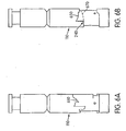
- FIG. 6A illustrates a plunger 110 with an upper helix 610 made according to the present invention.
- Upper helix 610 may optimize injection timing for an engine that includes plunger 110. As shown, upper helix 610 somewhat resembles a staircase. The specific form of upper helix 610 may depend on emissions data and/or empirical engine performance testing, as described above.
- transitions in steps may be related to transitions in discrete throttle settings. For instance, for certain embodiments, the width of certain steps may span about 25° of the circumference of plunger 110. Height of the various steps may vary.
- FIG. 6B illustrates an exemplary embodiment of a plunger 110 that includes an upper helix 650 and a reference helix 670.
- Upper helix 650 may reduce emissions for higher notches as compared with reference helix 670.
- the helix angle of an upper helix may not substantially change or may change only slightly (resembling a straight line, for example) at lower notches, and then may change more substantially at higher notches to optimize injection timing at those notches.
- FIG. 7 illustrates a manufacturing process 700 according to an embodiment of the present invention.
- an engine throttle setting in need of optimized injection timing is identified.
- a helix angle capable of optimizing injection timing for the identified engine throttle setting is determined. The determined helix angle may advance, retard, or not alter injection timing.
- a plunger for a fuel injector is formed.
- An upper helix of the plunger may include at least two segmented portions between points on the plunger respectively corresponding to a first and second throttle position. The segmented portions have unequal associated helix angles.
- One of the segmented portions may correspond to the throttle setting identified in task 701 and may have an associated helix angle substantially equal to the helix angle determined in task 710.
- a fuel injector that includes the plunger is assembled.
- the fuel injector may include a through-hardened chromium hot-work steel nozzle tip such as that described above.
- a machining device such as a programmable device, may be employed to manufacture the plunger.
- a plunger with an upper helix having multiple unequal helix angles may be formed from scratch.
- an existing plunger such as a plunger whose upper helix has substantially one helix angle, may be modified, such that the modified plunger has an upper helix having multiple unequal helix angles at desired positions of the plunger.
- This may be accomplished, for example, by adding or subtracting material in the region of the lower helix, preferably without changing the slope of the lower helix, (i.e., either moving the lower helix towards or away from the upper helix without changing the slope of the lower helix).
- the timing can be customized in accordance with the present invention to address difference types of emissions or contaminates.
- the present invention may relate to the railroad industry, there is a particular desire to reduce the amount of NOx emissions (nitrogen oxide and nitrogen dioxide emissions).
- NOx emissions nitrogen oxide and nitrogen dioxide emissions
- the emissions thereof is directly related to combustion temperature. Specifically, as combustion temperature goes down, NOx emissions goes down. As combustion temperature goes up, NOx emissions goes up. By retarding the timing or onset of combustion by changing the configuration of the upper helix at a particular notch in relation to a reference or prior art plunger, this will reduce the combustion temperature and hence reduce NOx emissions.
- a desired weighted NOx emissions is predetermined, and the upper or timing helix is cut or angled in a manner that achieves that desired level of emissions while simultaneously obtaining the best fuel efficiency for that emissions level. For example, in the event that a particular maximum emissions level is desired (e.g., as a maximum threshold that might be set by the Environmental Protection Agency for a particular type of engine) as measured in grams/BHP-HR.
- the emissions at each throttle position is measured to determine the throttle position or range of positions that are most detrimental to emissions.
- retarding the timing to reduce NOx emissions for example, at the most critical throttle positions (or notches in the case of a locomotive engine) a significant benefit to the total weighted emissions can be achieved with a relatively insignificant impact on fuel efficiency.
- retarding the timing at the throttle position(s) that have the greatest impact on emissions output a significant reduction in emissions can be achieved with the least fuel penalty.
- fuel efficiency is likewise decreased.
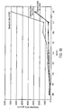
- Figure 8 illustrates the NOx emissions profile in grams per hour plotted against notch position for a switcher-type locomotive engine.
- the locomotive used was GP38-2 and the engine used was General Motors EMD (Model 16-645E).
- the engine utilizes a conventional prior art unit fuel injector having a standard, single slope timing helix. As shown towards the top of the graph, the EPA has conducted tests to determine the duty cycle of operation for a standard switcher-type locomotive at each notch position.
- the EPA has determined that an engine of this type runs 59.8% of the time in the idle position, 12.4% of the time at notch 1, 12.3% of the time at notch 2, 5.8% of the time at notch 3, 3.6% of the time in notch 4, 3.6% of the time at notch 5, 1.5% of the time at notch 6, .2% of the time at notch 7, and .8% of the time at notch 8.
- the cumulative duty cycle numbers are illustrated in the chart.
- the cumulative weighted NOx in grams per hour, taken as a percentage. For example, as illustrated, 81.10% of the cumulated weighted NOx emissions takes place at notches N5 and below.
- the inventors have determined that because 81.1% of accumulative weighted NOx emissions and grams per hour reside in notches N5 and below, it would be advantageous to reduce NOx emissions at those levels by retarding the timing at notches N5 and below to achieve the desired net total NOx emissions in grams per BHP-hour of 14.0.
- the timing may be retarded at at least one notch level (if not more) to achieve the reduction in NOx emissions as desired, while minimizing the fuel penalty associated with achieving that level of NOx emissions.
- the degree of retardation at the one or more throttle or notch positions may be established by trial and error after determining which notch positions are most critical in relation to NOx emissions. For example, once the data of Figure 9 is established, it becomes readily apparent that retarding the timing at notch 5 and perhaps notches below that level is particularly desirable. The extent to which each of the notches has its timing retarded in relation to the original reference plunger is one that may be established experimentally through trial and error. Alternatively complex algorithmic formula and software may be developed to derive the optimal level of retardation or advancement (if any) to achieve a desired emissions output with a minimized fuel penalty.
- Figure 10 illustrates a comparison of a plunger employing a standard or reference helix (prior art) for a switcher engine versus a plunger sample ("Switcher Helix #1") having a modified slope in comparison with a standard helix for that engine such that the timing thereof was retarded for notches N5 down through the idle positions.
- the amount of retardation at each notch is compared to the standard timing and is illustrated by reference to the timing in degrees relative to top dead center. As illustrated in Figure 11 , this retardation in the timing illustrated in Fig. 10 resulted in a total reduction of 1.8 grams/BHP-HR in comparison with the standard or reference helix.
- the weighted NOx emissions was reduced from 13.7 grams/bhp-hour to 11.9 grams of NOx/bhp-hour. In addition, this was achieved with only a 0.75% fuel penalty (i.e., a .75% decrease in combustion efficiency.)
- Figure 12 illustrates the test results using the same engine, but with another plunger (Switcher Helix 2) in which the timing was retarded for notches N6 and below, and a comparison with the standard or reference helix.
- Switchcher Helix 2 another plunger in which the timing was retarded for notches N6 and below, and a comparison with the standard or reference helix.
- this resulted in a reduction of weighted NOx from 13.7 grams/BHP-hour to 9.3 grams/BHP-hour, for a reduction of 4.4 grams/BHP-hour.
- this was achieved at a 1.9% fuel penalty.
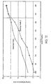
- Figure 14 illustrates an experiment that was conducted in order to determine what would happen if the timing for switcher helix 2 was uniformly retarded by changing the fly-wheel pointer position. This was conducted at four degrees after top dead center. As illustrated in Fig. 15 , this resulted in an undesirable fuel penalty of 12.8%.
- Figures 16-18 illustrate data derived for a different type of engine than the switcher engine discussed above with respect to Figures 8-15 .
- Figures 16-18 relate to a line-haul type engine (General Motors EMD 16-645E3B) used in locomotive model SD40-2.
- notch 8 represents a significantly high percentage of the total weighted NOx emissions when using the reference prior art plunger. Accordingly, it would be desirable to significantly retard the timing at notch 8 to improve NOx efficiency.
- the line hall helix at 4 degrees after top dead center had its slope modified relative to the standard helix for that engine by having the slope altered so that the timing is substantially retarded at notches N8-N3 in comparison with the standard helix.
- the timing was advanced in order to improve upon fuel efficiency at these lower notch levels since the retarded timing at the higher notches, e.g. notch 8 significantly improves upon the emissions characteristics at the higher level, thus enabling some room for improved fuel efficiencies at the lower notch levels to improve upon fuel economies in those lower notches so that the resulting weighted NOx level resulted in 6.7 grams/BHP-HR, with a 4% fuel penalty.
- Results are also shown where at 6 degrees after top dead center the timing was modified, and resulted in NOx level of 6.0 grams/BHP-HR, with an 8% fuel penalty.
- Fig. 18 illustrates NOx emissions with line-haul helixes at 4 and 6 degrees after top dead center in comparison with the standard helix. As illustrated, the total weighted NOx emissions at the higher notches (N6, N7, N8) was substantially reduced, especially N8, when line-haul helixes were used.
- helix or “helices” do not necessarily refer to a timing ridge of what is in fact a helix or of a helical shape.
- the upper timing line or ridge that has been formed in injector plungers have been helical in shape and have thus been referred to as the "upper timing helix” or the like.
- the upper timing structure formed in the plunger need not at all be shaped as a helix, as can be appreciated, for example, from the shape of the timing structures or helixes 330, 610, 650, etc.
- the term “helix” should refer broadly to the upper timing structure formed on the plunger.
Landscapes
- Engineering & Computer Science (AREA)
- Chemical & Material Sciences (AREA)
- Combustion & Propulsion (AREA)
- Mechanical Engineering (AREA)
- General Engineering & Computer Science (AREA)
- Fuel-Injection Apparatus (AREA)
Claims (5)
- Procédé de fabrication d'un injecteur de carburant, comprenant le fait :d'obtenir des données d'émissions pour ledit moteur à combustion à différentes positions de papillon de gaz (repos, N1, N2, N3, N4, N5, N6, N7 et N8), ledit moteur ayant des émissions différentes au moins aux première et deuxième positions de papillon de gaz dans lesdites positions de papillon de gaz différentes (repos, N1, N2, N3, N4, N5, N6, N7 et N8) ;de déterminer un premier angle d'hélice pour ledit piston plongeur (110) sur la base desdites données d'émissions pour une première position desdites positions de papillon de gaz (repos, N1, N2, N3, N4, N5, N6, N7 et N8),de déterminer un deuxième angle d'hélice pour ledit piston plongeur (110) sur la base desdites données d'émissions pour une deuxième position desdites positions de papillon de gaz (repos, N1, N2, N3, N4, N5, N6, N7 et N8),ledit premier angle d'hélice étant différent dudit deuxième angle d'hélice, etde former ledit piston plongeur (110) avec une hélice (180) comprenant au moins une partie de celle-ci avec ledit premier angle d'hélice et une partie de celle-ci avec ledit deuxième angle d'hélice.
- Procédé selon la revendication 1, comprenant en outre le fait
de déterminer un rendement de combustion auxdites positions de papillon de gaz différentes (repos, N1, N2, N3, N4, N5, N6, N7 et N8) ; et
d'utiliser ledit rendement de combustion dans la détermination dudit premier angle d'hélice et dudit deuxième angle d'hélice. - Procédé selon la revendication 2, dans lequel lesdites positions de papillon de gaz (repos, N1, N2, N3, N4, N5, N6, N7 et N8) sont des positions d'encoche discrètes.
- Procédé selon la revendication 1, dans lequel ladite obtention des données d'émission comprend le fait :d'obtenir lesdites données d'émissions en utilisant un mécanisme d'injection avec un piston plongeur de référence ayant une hélice de référence (310), ladite hélice de référence ayant un angle d'hélice de référence, ledit angle d'hélice de référence définissant un calage d'injection,ladite détermination desdits premier et deuxième angles d'hélice comprend le fait de déterminer, sur la base desdites données d'émissions, des angles d'hélice optimaux au moins à ladite première position desdites positions de papillon de gaz et à ladite deuxième position des positions de papillon de gaz dans lesdites positions de papillon de gaz différentes, etladite formation dudit piston plongeur (110) comprend le fait de former un piston plongeur optimal qui comporte lesdits angles d'hélice optimaux.
- Procédé selon la revendication 4, dans lequel ladite première position desdites positions de papillon de gaz se trouve à une position de papillon de gaz inférieure à ladite deuxième position desdites positions de papillon de gaz, et
dans lequel ladite formation dudit piston plongeur optimal (110) comprend le fait de modifier l'angle d'hélice optimal à ladite position de papillon de gaz inférieure de manière à ce que le calage d'injection soit retardé par rapport à celui pour ladite hélice de référence.
Applications Claiming Priority (2)
| Application Number | Priority Date | Filing Date | Title |
|---|---|---|---|
| US10/702,050 US6945233B2 (en) | 2002-12-23 | 2003-11-06 | System and method of optimizing fuel injection timing in a locomotive engine |
| PCT/US2004/036500 WO2005047687A1 (fr) | 2003-11-06 | 2004-11-03 | Systeme et procede pour optimiser l'avance a l'injection de carburant dans un moteur de locomotive |
Publications (2)
| Publication Number | Publication Date |
|---|---|
| EP1702155A1 EP1702155A1 (fr) | 2006-09-20 |
| EP1702155B1 true EP1702155B1 (fr) | 2013-05-29 |
Family
ID=34590701
Family Applications (1)
| Application Number | Title | Priority Date | Filing Date |
|---|---|---|---|
| EP04800619.1A Expired - Lifetime EP1702155B1 (fr) | 2003-11-06 | 2004-11-03 | Procede pour optimiser l'avance a l'injection de carburant dans un moteur de locomotive |
Country Status (7)
| Country | Link |
|---|---|
| US (1) | US6945233B2 (fr) |
| EP (1) | EP1702155B1 (fr) |
| JP (1) | JP2007510848A (fr) |
| AU (1) | AU2004288914B2 (fr) |
| CA (1) | CA2544927A1 (fr) |
| MX (1) | MXPA06005151A (fr) |
| WO (1) | WO2005047687A1 (fr) |
Families Citing this family (3)
| Publication number | Priority date | Publication date | Assignee | Title |
|---|---|---|---|---|
| US8656891B2 (en) * | 2005-01-27 | 2014-02-25 | Ted Stewart | Horizontal control surface for a fuel injector |
| US20070227508A1 (en) * | 2006-04-04 | 2007-10-04 | Haynes Corporation | Method of retarding injection timing of mechanical unit injectors using a modified pump barrel |
| US10989155B2 (en) | 2017-04-19 | 2021-04-27 | Progress Rail Services Corporation | Method of retarding injection timing of a fuel injector |
Family Cites Families (21)
| Publication number | Priority date | Publication date | Assignee | Title |
|---|---|---|---|---|
| GB723982A (en) | 1950-12-09 | 1955-02-16 | Gen Motors Corp | Improvements in internal combustion engines |
| US3567346A (en) * | 1969-07-14 | 1971-03-02 | Gen Motors Corp | Unit fuel injector with modulated injection |
| US3566849A (en) * | 1969-07-28 | 1971-03-02 | Gen Motors Corp | Fuel injector pump and limiting speed governor for internal combustion engine |
| US3885995A (en) | 1973-04-10 | 1975-05-27 | Boeing Co | Process for carburizing high alloy steels |
| DE2430668A1 (de) * | 1974-06-26 | 1976-01-15 | Maschf Augsburg Nuernberg Ag | Brennstoffeinspritzvorrichtung fuer eine selbstzuendende brennkraftmaschine |
| US4327694A (en) * | 1979-11-01 | 1982-05-04 | Caterpillar Tractor Co. | Unit fuel pump-injector with overfuel capability and timing retardation |
| WO1981001314A1 (fr) * | 1979-11-01 | 1981-05-14 | R Henson | Unite de pompe-injecteur de carburant avec possibilite de suralimentation et de retardement de la distribution |
| AT388214B (de) * | 1983-02-17 | 1989-05-26 | Steyr Daimler Puch Ag | Kraftstoff-einspritzaggregat fuer je einen zylinder eines dieselmotors |
| US4838232A (en) * | 1984-08-14 | 1989-06-13 | Ail Corporation | Fuel delivery control system |
| JPS6217364A (ja) | 1985-07-13 | 1987-01-26 | Niigata Eng Co Ltd | 内燃機関の燃料噴射ノズル |
| DE3804018A1 (de) * | 1987-06-10 | 1989-08-24 | Kloeckner Humboldt Deutz Ag | Einspritzpumpe mit voreinspritzung |
| US4886640A (en) * | 1988-08-22 | 1989-12-12 | Carpenter Technology Corporation | Hot work tool steel with good temper resistance |
| US5033442A (en) * | 1989-01-19 | 1991-07-23 | Cummins Engine Company, Inc. | Fuel injector with multiple variable timing |
| DE3923306A1 (de) * | 1989-07-14 | 1991-01-24 | Daimler Benz Ag | Schraegkantengesteuerte kraftstoffeinspritzpumpe fuer brennkraftmaschinen |
| US5048480A (en) * | 1990-03-15 | 1991-09-17 | Jacobs Brake Technology Corporation | Variable timing process and mechanism for a compression release engine retarder |
| US5409165A (en) * | 1993-03-19 | 1995-04-25 | Cummins Engine Company, Inc. | Wear resistant fuel injector plunger assembly |
| US5685273A (en) * | 1996-08-07 | 1997-11-11 | Bkm, Inc. | Method and apparatus for controlling fuel injection in an internal combustion engine |
| US6009850A (en) * | 1998-04-10 | 2000-01-04 | Alfred J. Buescher | High-pressure dual-feed-rate injector pump with grooved port-closing edge |
| US6305358B1 (en) * | 1998-12-21 | 2001-10-23 | Caterpillar Inc. | Method and apparatus for dynamic trimming of fuel system |
| US6321723B1 (en) * | 2000-08-07 | 2001-11-27 | Alfred J. Buescher | Method of retarding injection timing |
| US6470844B2 (en) | 2001-01-31 | 2002-10-29 | Csx Transportation, Inc. | System and method for supplying auxiliary power to a large diesel engine |
-
2003
- 2003-11-06 US US10/702,050 patent/US6945233B2/en not_active Expired - Lifetime
-
2004
- 2004-11-03 CA CA002544927A patent/CA2544927A1/fr not_active Abandoned
- 2004-11-03 JP JP2006538444A patent/JP2007510848A/ja not_active Withdrawn
- 2004-11-03 EP EP04800619.1A patent/EP1702155B1/fr not_active Expired - Lifetime
- 2004-11-03 AU AU2004288914A patent/AU2004288914B2/en not_active Expired
- 2004-11-03 WO PCT/US2004/036500 patent/WO2005047687A1/fr not_active Ceased
- 2004-11-03 MX MXPA06005151A patent/MXPA06005151A/es active IP Right Grant
Also Published As
| Publication number | Publication date |
|---|---|
| WO2005047687A1 (fr) | 2005-05-26 |
| CA2544927A1 (fr) | 2005-05-26 |
| US20040139948A1 (en) | 2004-07-22 |
| US6945233B2 (en) | 2005-09-20 |
| AU2004288914A1 (en) | 2005-05-26 |
| JP2007510848A (ja) | 2007-04-26 |
| MXPA06005151A (es) | 2007-01-26 |
| EP1702155A1 (fr) | 2006-09-20 |
| AU2004288914B2 (en) | 2010-04-15 |
Similar Documents
| Publication | Publication Date | Title |
|---|---|---|
| CN100529336C (zh) | 多级燃料喷射内燃机 | |
| JP2021536544A (ja) | 内燃機関の再始動される気筒に対する分割直接噴射 | |
| EP0454439B1 (fr) | Pompe-injecteur de combustible | |
| US10024223B2 (en) | Two-stroke internal combustion engine | |
| US6799561B2 (en) | System and method of optimizing fuel injection timing in locomotive engine | |
| EP1702155B1 (fr) | Procede pour optimiser l'avance a l'injection de carburant dans un moteur de locomotive | |
| US5823168A (en) | Fuel injection pump | |
| Russell et al. | Modulation of injection rate to improve direct injection diesel engine noise | |
| US5911207A (en) | Fuel injection pump | |
| JP2003056390A (ja) | 直噴内燃エンジン用の燃料噴射制御方法 | |
| CA2465771C (fr) | Dispositif d'optimisation d'injecteurs pour ameliorer la consommation et les emissions | |
| US10711685B2 (en) | Internal combustion engine | |
| US10989155B2 (en) | Method of retarding injection timing of a fuel injector | |
| EP3626960A1 (fr) | Injecteurs diesel et procédé de fabrication d'injecteurs de diesel | |
| US10378464B2 (en) | Control device for internal combustion engine | |
| JP2008025491A (ja) | 内燃機関 | |
| Schulte et al. | The Contribution of the fuel injection system to meeting future demands on truck diesel engines | |
| CN217129671U (zh) | 一种船用柴油机凸轮轴 | |
| CN114992023B (zh) | 一种适应负碳生物燃料的航空发动机喷油控制方法 | |
| KR100350876B1 (ko) | 디젤엔진의 연료 분사펌프 | |
| JPS61229930A (ja) | 内燃機関用分配型燃料噴射ポンプ | |
| Aghav et al. | Optimization of Off-highway Engine for TIER-II Emission Norms Using Cost Effective Fuel Injection Equipment | |
| JPH11117828A (ja) | 内燃機関用燃料噴射装置 | |
| DE102007031523A1 (de) | Steuervorrichtung für einen Direkteinspritzmotor | |
| JPH10213050A (ja) | 蓄圧式燃料噴射装置 |
Legal Events
| Date | Code | Title | Description |
|---|---|---|---|
| PUAI | Public reference made under article 153(3) epc to a published international application that has entered the european phase |
Free format text: ORIGINAL CODE: 0009012 |
|
| 17P | Request for examination filed |
Effective date: 20060606 |
|
| AK | Designated contracting states |
Kind code of ref document: A1 Designated state(s): AT BE BG CH CY CZ DE DK EE ES FI FR GB GR HU IE IS IT LI LU MC NL PL PT RO SE SI SK TR |
|
| DAX | Request for extension of the european patent (deleted) | ||
| 17Q | First examination report despatched |
Effective date: 20071126 |
|
| GRAP | Despatch of communication of intention to grant a patent |
Free format text: ORIGINAL CODE: EPIDOSNIGR1 |
|
| GRAS | Grant fee paid |
Free format text: ORIGINAL CODE: EPIDOSNIGR3 |
|
| GRAA | (expected) grant |
Free format text: ORIGINAL CODE: 0009210 |
|
| AK | Designated contracting states |
Kind code of ref document: B1 Designated state(s): AT BE BG CH CY CZ DE DK EE ES FI FR GB GR HU IE IS IT LI LU MC NL PL PT RO SE SI SK TR |
|
| REG | Reference to a national code |
Ref country code: GB Ref legal event code: FG4D |
|
| REG | Reference to a national code |
Ref country code: CH Ref legal event code: EP |
|
| REG | Reference to a national code |
Ref country code: AT Ref legal event code: REF Ref document number: 614568 Country of ref document: AT Kind code of ref document: T Effective date: 20130615 |
|
| REG | Reference to a national code |
Ref country code: IE Ref legal event code: FG4D |
|
| REG | Reference to a national code |
Ref country code: DE Ref legal event code: R096 Ref document number: 602004042307 Country of ref document: DE Effective date: 20130725 |
|
| REG | Reference to a national code |
Ref country code: AT Ref legal event code: MK05 Ref document number: 614568 Country of ref document: AT Kind code of ref document: T Effective date: 20130529 |
|
| PG25 | Lapsed in a contracting state [announced via postgrant information from national office to epo] |
Ref country code: AT Free format text: LAPSE BECAUSE OF FAILURE TO SUBMIT A TRANSLATION OF THE DESCRIPTION OR TO PAY THE FEE WITHIN THE PRESCRIBED TIME-LIMIT Effective date: 20130529 Ref country code: SE Free format text: LAPSE BECAUSE OF FAILURE TO SUBMIT A TRANSLATION OF THE DESCRIPTION OR TO PAY THE FEE WITHIN THE PRESCRIBED TIME-LIMIT Effective date: 20130529 Ref country code: FI Free format text: LAPSE BECAUSE OF FAILURE TO SUBMIT A TRANSLATION OF THE DESCRIPTION OR TO PAY THE FEE WITHIN THE PRESCRIBED TIME-LIMIT Effective date: 20130529 Ref country code: SI Free format text: LAPSE BECAUSE OF FAILURE TO SUBMIT A TRANSLATION OF THE DESCRIPTION OR TO PAY THE FEE WITHIN THE PRESCRIBED TIME-LIMIT Effective date: 20130529 Ref country code: ES Free format text: LAPSE BECAUSE OF FAILURE TO SUBMIT A TRANSLATION OF THE DESCRIPTION OR TO PAY THE FEE WITHIN THE PRESCRIBED TIME-LIMIT Effective date: 20130909 Ref country code: GR Free format text: LAPSE BECAUSE OF FAILURE TO SUBMIT A TRANSLATION OF THE DESCRIPTION OR TO PAY THE FEE WITHIN THE PRESCRIBED TIME-LIMIT Effective date: 20130830 Ref country code: PT Free format text: LAPSE BECAUSE OF FAILURE TO SUBMIT A TRANSLATION OF THE DESCRIPTION OR TO PAY THE FEE WITHIN THE PRESCRIBED TIME-LIMIT Effective date: 20130930 Ref country code: IS Free format text: LAPSE BECAUSE OF FAILURE TO SUBMIT A TRANSLATION OF THE DESCRIPTION OR TO PAY THE FEE WITHIN THE PRESCRIBED TIME-LIMIT Effective date: 20130929 |
|
| REG | Reference to a national code |
Ref country code: NL Ref legal event code: VDEP Effective date: 20130529 |
|
| PG25 | Lapsed in a contracting state [announced via postgrant information from national office to epo] |
Ref country code: BG Free format text: LAPSE BECAUSE OF FAILURE TO SUBMIT A TRANSLATION OF THE DESCRIPTION OR TO PAY THE FEE WITHIN THE PRESCRIBED TIME-LIMIT Effective date: 20130829 Ref country code: PL Free format text: LAPSE BECAUSE OF FAILURE TO SUBMIT A TRANSLATION OF THE DESCRIPTION OR TO PAY THE FEE WITHIN THE PRESCRIBED TIME-LIMIT Effective date: 20130529 |
|
| PG25 | Lapsed in a contracting state [announced via postgrant information from national office to epo] |
Ref country code: DK Free format text: LAPSE BECAUSE OF FAILURE TO SUBMIT A TRANSLATION OF THE DESCRIPTION OR TO PAY THE FEE WITHIN THE PRESCRIBED TIME-LIMIT Effective date: 20130529 Ref country code: EE Free format text: LAPSE BECAUSE OF FAILURE TO SUBMIT A TRANSLATION OF THE DESCRIPTION OR TO PAY THE FEE WITHIN THE PRESCRIBED TIME-LIMIT Effective date: 20130529 Ref country code: CZ Free format text: LAPSE BECAUSE OF FAILURE TO SUBMIT A TRANSLATION OF THE DESCRIPTION OR TO PAY THE FEE WITHIN THE PRESCRIBED TIME-LIMIT Effective date: 20130529 Ref country code: BE Free format text: LAPSE BECAUSE OF FAILURE TO SUBMIT A TRANSLATION OF THE DESCRIPTION OR TO PAY THE FEE WITHIN THE PRESCRIBED TIME-LIMIT Effective date: 20130529 Ref country code: SK Free format text: LAPSE BECAUSE OF FAILURE TO SUBMIT A TRANSLATION OF THE DESCRIPTION OR TO PAY THE FEE WITHIN THE PRESCRIBED TIME-LIMIT Effective date: 20130529 |
|
| PG25 | Lapsed in a contracting state [announced via postgrant information from national office to epo] |
Ref country code: NL Free format text: LAPSE BECAUSE OF FAILURE TO SUBMIT A TRANSLATION OF THE DESCRIPTION OR TO PAY THE FEE WITHIN THE PRESCRIBED TIME-LIMIT Effective date: 20130529 Ref country code: RO Free format text: LAPSE BECAUSE OF FAILURE TO SUBMIT A TRANSLATION OF THE DESCRIPTION OR TO PAY THE FEE WITHIN THE PRESCRIBED TIME-LIMIT Effective date: 20130529 Ref country code: IT Free format text: LAPSE BECAUSE OF FAILURE TO SUBMIT A TRANSLATION OF THE DESCRIPTION OR TO PAY THE FEE WITHIN THE PRESCRIBED TIME-LIMIT Effective date: 20130529 |
|
| PLBE | No opposition filed within time limit |
Free format text: ORIGINAL CODE: 0009261 |
|
| STAA | Information on the status of an ep patent application or granted ep patent |
Free format text: STATUS: NO OPPOSITION FILED WITHIN TIME LIMIT |
|
| 26N | No opposition filed |
Effective date: 20140303 |
|
| REG | Reference to a national code |
Ref country code: DE Ref legal event code: R097 Ref document number: 602004042307 Country of ref document: DE Effective date: 20140303 |
|
| REG | Reference to a national code |
Ref country code: CH Ref legal event code: PL |
|
| GBPC | Gb: european patent ceased through non-payment of renewal fee |
Effective date: 20131103 |
|
| PG25 | Lapsed in a contracting state [announced via postgrant information from national office to epo] |
Ref country code: MC Free format text: LAPSE BECAUSE OF FAILURE TO SUBMIT A TRANSLATION OF THE DESCRIPTION OR TO PAY THE FEE WITHIN THE PRESCRIBED TIME-LIMIT Effective date: 20130529 Ref country code: LI Free format text: LAPSE BECAUSE OF NON-PAYMENT OF DUE FEES Effective date: 20131130 Ref country code: CH Free format text: LAPSE BECAUSE OF NON-PAYMENT OF DUE FEES Effective date: 20131130 |
|
| REG | Reference to a national code |
Ref country code: FR Ref legal event code: ST Effective date: 20140731 |
|
| REG | Reference to a national code |
Ref country code: IE Ref legal event code: MM4A |
|
| REG | Reference to a national code |
Ref country code: DE Ref legal event code: R119 Ref document number: 602004042307 Country of ref document: DE Effective date: 20140603 |
|
| PG25 | Lapsed in a contracting state [announced via postgrant information from national office to epo] |
Ref country code: DE Free format text: LAPSE BECAUSE OF NON-PAYMENT OF DUE FEES Effective date: 20140603 |
|
| PG25 | Lapsed in a contracting state [announced via postgrant information from national office to epo] |
Ref country code: IE Free format text: LAPSE BECAUSE OF NON-PAYMENT OF DUE FEES Effective date: 20131103 |
|
| PG25 | Lapsed in a contracting state [announced via postgrant information from national office to epo] |
Ref country code: GB Free format text: LAPSE BECAUSE OF NON-PAYMENT OF DUE FEES Effective date: 20131103 Ref country code: FR Free format text: LAPSE BECAUSE OF NON-PAYMENT OF DUE FEES Effective date: 20131202 |
|
| PG25 | Lapsed in a contracting state [announced via postgrant information from national office to epo] |
Ref country code: CY Free format text: LAPSE BECAUSE OF FAILURE TO SUBMIT A TRANSLATION OF THE DESCRIPTION OR TO PAY THE FEE WITHIN THE PRESCRIBED TIME-LIMIT Effective date: 20130529 Ref country code: TR Free format text: LAPSE BECAUSE OF FAILURE TO SUBMIT A TRANSLATION OF THE DESCRIPTION OR TO PAY THE FEE WITHIN THE PRESCRIBED TIME-LIMIT Effective date: 20130529 |
|
| PG25 | Lapsed in a contracting state [announced via postgrant information from national office to epo] |
Ref country code: HU Free format text: LAPSE BECAUSE OF FAILURE TO SUBMIT A TRANSLATION OF THE DESCRIPTION OR TO PAY THE FEE WITHIN THE PRESCRIBED TIME-LIMIT; INVALID AB INITIO Effective date: 20041103 Ref country code: LU Free format text: LAPSE BECAUSE OF NON-PAYMENT OF DUE FEES Effective date: 20131103 |