EP1702176B1 - Wärmekraftanlage mit sequentieller verbrennung und reduziertem co2-ausstoss sowie verfahren zum betreiben einer derartigen anlage - Google Patents
Wärmekraftanlage mit sequentieller verbrennung und reduziertem co2-ausstoss sowie verfahren zum betreiben einer derartigen anlage Download PDFInfo
- Publication number
- EP1702176B1 EP1702176B1 EP04820847A EP04820847A EP1702176B1 EP 1702176 B1 EP1702176 B1 EP 1702176B1 EP 04820847 A EP04820847 A EP 04820847A EP 04820847 A EP04820847 A EP 04820847A EP 1702176 B1 EP1702176 B1 EP 1702176B1
- Authority
- EP
- European Patent Office
- Prior art keywords
- pressure turbine
- combustion
- turbine stage
- exhaust gas
- low
- Prior art date
- Legal status (The legal status is an assumption and is not a legal conclusion. Google has not performed a legal analysis and makes no representation as to the accuracy of the status listed.)
- Expired - Lifetime
Links
- 0 CCCC=C1**CC*1 Chemical compound CCCC=C1**CC*1 0.000 description 1
Images


Classifications
-
- F—MECHANICAL ENGINEERING; LIGHTING; HEATING; WEAPONS; BLASTING
- F23—COMBUSTION APPARATUS; COMBUSTION PROCESSES
- F23C—METHODS OR APPARATUS FOR COMBUSTION USING FLUID FUEL OR SOLID FUEL SUSPENDED IN A CARRIER GAS OR AIR
- F23C13/00—Apparatus in which combustion takes place in the presence of catalytic material
-
- C—CHEMISTRY; METALLURGY
- C01—INORGANIC CHEMISTRY
- C01B—NON-METALLIC ELEMENTS; COMPOUNDS THEREOF; METALLOIDS OR COMPOUNDS THEREOF NOT COVERED BY SUBCLASS C01C
- C01B3/00—Hydrogen; Gaseous mixtures containing hydrogen; Separation of hydrogen from mixtures containing it; Purification of hydrogen; Reversible storage of hydrogen
- C01B3/02—Production of hydrogen; Production of gaseous mixtures containing hydrogen
- C01B3/32—Production of hydrogen; Production of gaseous mixtures containing hydrogen by reaction of gaseous or liquid organic compounds with gasifying agents, e.g. water, carbon dioxide or air
- C01B3/34—Production of hydrogen; Production of gaseous mixtures containing hydrogen by reaction of gaseous or liquid organic compounds with gasifying agents, e.g. water, carbon dioxide or air by reaction of hydrocarbons with gasifying agents
- C01B3/38—Production of hydrogen; Production of gaseous mixtures containing hydrogen by reaction of gaseous or liquid organic compounds with gasifying agents, e.g. water, carbon dioxide or air by reaction of hydrocarbons with gasifying agents using catalysts
- C01B3/386—Catalytic partial combustion
-
- F—MECHANICAL ENGINEERING; LIGHTING; HEATING; WEAPONS; BLASTING
- F02—COMBUSTION ENGINES; HOT-GAS OR COMBUSTION-PRODUCT ENGINE PLANTS
- F02C—GAS-TURBINE PLANTS; AIR INTAKES FOR JET-PROPULSION PLANTS; CONTROLLING FUEL SUPPLY IN AIR-BREATHING JET-PROPULSION PLANTS
- F02C1/00—Gas-turbine plants characterised by the use of hot gases or unheated pressurised gases, as the working fluid
- F02C1/04—Gas-turbine plants characterised by the use of hot gases or unheated pressurised gases, as the working fluid the working fluid being heated indirectly
- F02C1/08—Semi-closed cycles
-
- F—MECHANICAL ENGINEERING; LIGHTING; HEATING; WEAPONS; BLASTING
- F02—COMBUSTION ENGINES; HOT-GAS OR COMBUSTION-PRODUCT ENGINE PLANTS
- F02C—GAS-TURBINE PLANTS; AIR INTAKES FOR JET-PROPULSION PLANTS; CONTROLLING FUEL SUPPLY IN AIR-BREATHING JET-PROPULSION PLANTS
- F02C3/00—Gas-turbine plants characterised by the use of combustion products as the working fluid
- F02C3/34—Gas-turbine plants characterised by the use of combustion products as the working fluid with recycling of part of the working fluid, i.e. semi-closed cycles with combustion products in the closed part of the cycle
-
- F—MECHANICAL ENGINEERING; LIGHTING; HEATING; WEAPONS; BLASTING
- F02—COMBUSTION ENGINES; HOT-GAS OR COMBUSTION-PRODUCT ENGINE PLANTS
- F02C—GAS-TURBINE PLANTS; AIR INTAKES FOR JET-PROPULSION PLANTS; CONTROLLING FUEL SUPPLY IN AIR-BREATHING JET-PROPULSION PLANTS
- F02C6/00—Plural gas-turbine plants; Combinations of gas-turbine plants with other apparatus; Adaptations of gas-turbine plants for special use
- F02C6/003—Gas-turbine plants with heaters between turbine stages
-
- F—MECHANICAL ENGINEERING; LIGHTING; HEATING; WEAPONS; BLASTING
- F02—COMBUSTION ENGINES; HOT-GAS OR COMBUSTION-PRODUCT ENGINE PLANTS
- F02C—GAS-TURBINE PLANTS; AIR INTAKES FOR JET-PROPULSION PLANTS; CONTROLLING FUEL SUPPLY IN AIR-BREATHING JET-PROPULSION PLANTS
- F02C6/00—Plural gas-turbine plants; Combinations of gas-turbine plants with other apparatus; Adaptations of gas-turbine plants for special use
- F02C6/18—Plural gas-turbine plants; Combinations of gas-turbine plants with other apparatus; Adaptations of gas-turbine plants for special use using the waste heat of gas-turbine plants outside the plants themselves, e.g. gas-turbine power heat plants
-
- F—MECHANICAL ENGINEERING; LIGHTING; HEATING; WEAPONS; BLASTING
- F23—COMBUSTION APPARATUS; COMBUSTION PROCESSES
- F23C—METHODS OR APPARATUS FOR COMBUSTION USING FLUID FUEL OR SOLID FUEL SUSPENDED IN A CARRIER GAS OR AIR
- F23C6/00—Combustion apparatus characterised by the combination of two or more combustion chambers or combustion zones, e.g. for staged combustion
- F23C6/04—Combustion apparatus characterised by the combination of two or more combustion chambers or combustion zones, e.g. for staged combustion in series connection
- F23C6/042—Combustion apparatus characterised by the combination of two or more combustion chambers or combustion zones, e.g. for staged combustion in series connection with fuel supply in stages
-
- F—MECHANICAL ENGINEERING; LIGHTING; HEATING; WEAPONS; BLASTING
- F23—COMBUSTION APPARATUS; COMBUSTION PROCESSES
- F23C—METHODS OR APPARATUS FOR COMBUSTION USING FLUID FUEL OR SOLID FUEL SUSPENDED IN A CARRIER GAS OR AIR
- F23C9/00—Combustion apparatus characterised by arrangements for returning combustion products or flue gases to the combustion chamber
- F23C9/08—Combustion apparatus characterised by arrangements for returning combustion products or flue gases to the combustion chamber for reducing temperature in combustion chamber, e.g. for protecting walls of combustion chamber
-
- F—MECHANICAL ENGINEERING; LIGHTING; HEATING; WEAPONS; BLASTING
- F23—COMBUSTION APPARATUS; COMBUSTION PROCESSES
- F23R—GENERATING COMBUSTION PRODUCTS OF HIGH PRESSURE OR HIGH VELOCITY, e.g. GAS-TURBINE COMBUSTION CHAMBERS
- F23R3/00—Continuous combustion chambers using liquid or gaseous fuel
- F23R3/28—Continuous combustion chambers using liquid or gaseous fuel characterised by the fuel supply
- F23R3/34—Feeding into different combustion zones
- F23R3/346—Feeding into different combustion zones for staged combustion
-
- C—CHEMISTRY; METALLURGY
- C01—INORGANIC CHEMISTRY
- C01B—NON-METALLIC ELEMENTS; COMPOUNDS THEREOF; METALLOIDS OR COMPOUNDS THEREOF NOT COVERED BY SUBCLASS C01C
- C01B2203/00—Integrated processes for the production of hydrogen or synthesis gas
- C01B2203/02—Processes for making hydrogen or synthesis gas
- C01B2203/025—Processes for making hydrogen or synthesis gas containing a partial oxidation step
- C01B2203/0261—Processes for making hydrogen or synthesis gas containing a partial oxidation step containing a catalytic partial oxidation step [CPO]
-
- C—CHEMISTRY; METALLURGY
- C01—INORGANIC CHEMISTRY
- C01B—NON-METALLIC ELEMENTS; COMPOUNDS THEREOF; METALLOIDS OR COMPOUNDS THEREOF NOT COVERED BY SUBCLASS C01C
- C01B2203/00—Integrated processes for the production of hydrogen or synthesis gas
- C01B2203/06—Integration with other chemical processes
-
- C—CHEMISTRY; METALLURGY
- C01—INORGANIC CHEMISTRY
- C01B—NON-METALLIC ELEMENTS; COMPOUNDS THEREOF; METALLOIDS OR COMPOUNDS THEREOF NOT COVERED BY SUBCLASS C01C
- C01B2203/00—Integrated processes for the production of hydrogen or synthesis gas
- C01B2203/80—Aspect of integrated processes for the production of hydrogen or synthesis gas not covered by groups C01B2203/02 - C01B2203/1695
- C01B2203/84—Energy production
-
- F—MECHANICAL ENGINEERING; LIGHTING; HEATING; WEAPONS; BLASTING
- F23—COMBUSTION APPARATUS; COMBUSTION PROCESSES
- F23C—METHODS OR APPARATUS FOR COMBUSTION USING FLUID FUEL OR SOLID FUEL SUSPENDED IN A CARRIER GAS OR AIR
- F23C2201/00—Staged combustion
- F23C2201/40—Intermediate treatments between stages
-
- F—MECHANICAL ENGINEERING; LIGHTING; HEATING; WEAPONS; BLASTING
- F23—COMBUSTION APPARATUS; COMBUSTION PROCESSES
- F23C—METHODS OR APPARATUS FOR COMBUSTION USING FLUID FUEL OR SOLID FUEL SUSPENDED IN A CARRIER GAS OR AIR
- F23C2202/00—Fluegas recirculation
- F23C2202/30—Premixing fluegas with combustion air
-
- F—MECHANICAL ENGINEERING; LIGHTING; HEATING; WEAPONS; BLASTING
- F23—COMBUSTION APPARATUS; COMBUSTION PROCESSES
- F23C—METHODS OR APPARATUS FOR COMBUSTION USING FLUID FUEL OR SOLID FUEL SUSPENDED IN A CARRIER GAS OR AIR
- F23C2900/00—Special features of, or arrangements for combustion apparatus using fluid fuels or solid fuels suspended in air; Combustion processes therefor
- F23C2900/09001—Cooling flue gas before returning them to flame or combustion chamber
-
- F—MECHANICAL ENGINEERING; LIGHTING; HEATING; WEAPONS; BLASTING
- F23—COMBUSTION APPARATUS; COMBUSTION PROCESSES
- F23D—BURNERS
- F23D2210/00—Noise abatement
-
- F—MECHANICAL ENGINEERING; LIGHTING; HEATING; WEAPONS; BLASTING
- F23—COMBUSTION APPARATUS; COMBUSTION PROCESSES
- F23R—GENERATING COMBUSTION PRODUCTS OF HIGH PRESSURE OR HIGH VELOCITY, e.g. GAS-TURBINE COMBUSTION CHAMBERS
- F23R2900/00—Special features of, or arrangements for continuous combustion chambers; Combustion processes therefor
- F23R2900/00014—Reducing thermo-acoustic vibrations by passive means, e.g. by Helmholtz resonators
-
- F—MECHANICAL ENGINEERING; LIGHTING; HEATING; WEAPONS; BLASTING
- F23—COMBUSTION APPARATUS; COMBUSTION PROCESSES
- F23R—GENERATING COMBUSTION PRODUCTS OF HIGH PRESSURE OR HIGH VELOCITY, e.g. GAS-TURBINE COMBUSTION CHAMBERS
- F23R2900/00—Special features of, or arrangements for continuous combustion chambers; Combustion processes therefor
- F23R2900/00016—Retrofitting in general, e.g. to respect new regulations on pollution
-
- F—MECHANICAL ENGINEERING; LIGHTING; HEATING; WEAPONS; BLASTING
- F23—COMBUSTION APPARATUS; COMBUSTION PROCESSES
- F23R—GENERATING COMBUSTION PRODUCTS OF HIGH PRESSURE OR HIGH VELOCITY, e.g. GAS-TURBINE COMBUSTION CHAMBERS
- F23R2900/00—Special features of, or arrangements for continuous combustion chambers; Combustion processes therefor
- F23R2900/03341—Sequential combustion chambers or burners
Definitions
- the invention relates to a thermal power plant, preferably a gas turbine plant, with sequential combustion and reduced CO 2 emission, the following via at least one flow channel in series interconnected components comprising a Verbrennungszuluft compressor unit, a first combustion chamber, a high-pressure turbine stage, a second Combustion chamber and a low-pressure turbine stage, wherein the second combustion chamber and / or the low-pressure turbine stage can be supplied with a cooling gas flow for cooling purposes.
- US. 6 199 363 B discloses such a thermal power plant. Further, a method of operating a thermal power plant of the above type will be described.
- it is compressed in a manner known per se by means of the combustion air compressor unit of the gas turbine plant, wherein the recirculated exhaust gas is diluted with fresh air, whereby on the one hand the oxygen content of the combustion air to be compressed in the way of the compressor unit and the CO 2 concentration of the recirculated Be reduced exhaust gas.
- the invention has the object of providing a thermal power plant preferably a gas turbine plant with sequential combustion and reduced CO 2 emissions according to the preamble of claim 1 such that with As efficient as possible a CO 2 separation from the exhaust gas stream of a gas turbine plant is possible as little as possible, plant technical effort, without affecting the operating behavior and in particular the emission behavior of the gas turbine plant sustainable.
- the measure according to the invention is also intended to allow the possibility of retrofitting on gas turbines already in operation. It is also necessary to specify a corresponding method for operating a gas turbine plant of this type.
- claim 16 is a method for operating a thermal power plant, preferably gas turbine plant.
- the concept of the invention advantageously further features are the subject of the dependent claims and in particular the description with reference to the exemplary embodiments.
- a thermal power plant preferably gas turbine plant with sequential combustion and reduced CO 2 discharge, the following connected via at least one flow channel in series components comprising a Verbrennungszu poverty compressor unit, a first combustion chamber, a high-pressure turbine stage, a second combustion chamber and a low-pressure turbine stage, wherein the second combustion chamber and / or the low-pressure turbine stage can be supplied with a cooling gas stream for cooling purposes, further developed such that a recirculation line is provided which feeds at least a portion of an exhaust gas stream emerging from the low-pressure turbine stage to a cooling unit.
- At least a portion of the compressed exhaust gas stream exiting the cooling unit is supplied as cooling gas flow via a second combustion chamber and / or low pressure turbine stage cooling line for cooling purposes, whereby the gas turbine components exposed to the hot gases generated within the second combustion chamber can be effectively cooled.
- a CO 2 -Abborgeiki is provided which separates at least parts of CO 2 from the cooling gas stream.
- the invention thus essentially builds on a gas turbine plant with sequential combustion at the recirculated exhaust gas is compressed via an appropriately provided compressor unit to an intermediate pressure on which the CO 2 separation takes place and which moreover allows the CO 2 depleted offgas stream to flow as the cooling gas stream at the intermediate pressure level for purposes of cooling into the second combustion chamber and preferably also to feed into the low-pressure turbine stage.
- the precompressed, recirculated exhaust stream is passed through a radiator prior to entering the CO 2 separation unit.
- the used for cooling the second combustion chamber part of the cooling gas flow is heated by the sequential combustion back to the working temperature of the low-pressure turbine, whereby no loss of efficiency arises. Further details may be taken from the embodiments with reference to the following figures.
- the firing of the second combustion chamber provides for the use of a partial oxidation in which the second combustion chamber is combined with an oxidation unit to set a stoichiometric combustion by the fuel for firing the second combustion chamber at least partially is oxidized with release of hydrogen and at least with the CO 2 used as the cooling gas depleted exhaust gas stream is brought to form a stoichiometric fuel-oxygen mixture for ignition.
- the hot gases emerging from the high-pressure turbine stage can be proportionally admixed with the cooling gas stream.
- an extra for the compression of the Recirculated exhaust gas flow provided exhaust gas compressor unit for increasing the pressure of the exhaust gas flow to a certain intermediate pressure level for further feeding as cooling gas flow into the sequential combustion unit described above and in the low-pressure turbine stage.
- the method according to the invention for operating a sequential combustion and reduced CO 2 thermal power plant is characterized in that at least a portion of the exhaust gas leaving the low-pressure turbine stage is recirculated, compressed and supplied to CO 2 capture for CO 2 recovery and that the CO 2 depleted offgas stream is also provided as a cooling gas stream for cooling the second combustion chamber and / or the low-pressure turbine stage at the same time.
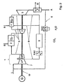
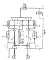
- FIG. 2 shows a simplified schematic process diagram of a gas turbine plant with sequential combustion known per se.
- the gas turbine plant consists essentially of a high-pressure turbine stage 3 and a low-pressure turbine stage 5 with an intervening sequential combustion 4.
- Supply air L is compressed in a Verbrennungszu Kunststoff compressor unit 1 via two compressor stages LP, HP to a high pressure level in a standard combustion chamber 2, this air with fuel B premixed and burned.
- the hot gas generated in the combustion chamber 3 is then expanded in the high-pressure turbine stage 3 to the intermediate pressure. Since the hot gas originating from the first lean premix combustion still contains more than half of its original oxygen content, fuel B is again added immediately before a special sequential combustion chamber 4 and ignited.
- This reheated hot gas relaxes downstream in a low-pressure turbine stage 5 to atmospheric pressure, which ultimately the relaxed hot gases are released in the form of an exhaust stream A in the free atmosphere.
- a portion of the pre-compressed in the low-pressure compressor LP combustion air supply is diverted and cooled by a cooling unit KA1 and fed to the sequential combustion chamber 4 and also the low-pressure turbine stage 5 for cooling purposes
- the exiting from the low-pressure turbine stage 5 exhaust gas A is recirculated via a recirculation line 6 in the supply air of the low-pressure compressor unit 7 in which the recirculated exhaust gas is mixed with the supply air and compressed to an intermediate pressure level.
- the recirculated exhaust gas A along the recirculation line 6 passes through a heat exchanger unit D, at which a heat transfer to a steam cycle, for example, to drive a steam turbine, not shown, takes place.
- the recirculation line 6 provides a cooler unit KA1 in which, on the one hand, the exhaust gas is cooled and dehumidified by way of condensation.
- the depleted from CO 2 -Abscheideiki 9 CO 2 exiting the exhaust gas stream is supplied in addition for cooling purposes the sequential burner unit 4 and the low-pressure turbine stage. 5 Wherein the part of the cooling gas flow used for cooling the second combustion chamber is heated again to the working temperature of the low-pressure turbine by the sequential combustion, whereby no loss of efficiency arises.
- admixture of the recirculated exhaust gas into the combustion air L takes place to an extent in which the oxygen content in the supply air of the combustion chamber 2 is just sufficient for the combustion of the supplied fuel B.
- the sequential combustion takes place in the combustion chamber 4 under oxygen deficiency.
- fuel B is first reacted under oxygen deficiency in the context of a so-called oxidation unit 11.
- the oxidation unit 11 is advantageously designed as a catalyst unit, which is supplied to the one to be oxidized fuel B and the other an amount of oxygen in the range between 20 and 75% of the theoretical oxygen demand for a complete oxidation of the fuel.
- part of the hydrogen is separated off from the hydrocarbon compounds of the fuel B and is present after the partial oxidation stage 11 as free hydrogen in the hot exit mixture before entering the sequential firing stage 4. If the hot gases emerging from the high-pressure turbine stage 3 are now supplied to the sequential firing stage 4 with this gas mixture containing hydrogen, the high temperature and the high reactivity of the hydrogen contained lead to a spontaneous reaction and the complete burnout of the hydrogen, CO and hydrogen residual hydrocarbons remaining fuel.
- the high reactivity of the burner mixture leads to a stable forming combustion within the sequential firing stage 4, so that the aforementioned disadvantages with regard to the occurrence of thermoacoustic vibrations, high CO emissions and extinguishing the premix burner flame can be completely avoided.
- a separate exhaust compressor unit 7 is provided on a common shaft W, along which the combustion air compressor unit 1 and the high and low pressure turbine stage 3, 5 are arranged, in which exclusively the recirculated exhaust gas via the recirculation line 6 and compressed via the cooler unit KA2 CO 2 separation unit 9 is supplied.
- the high CO 2 concentration in the exhaust gas is maintained, whereby an increase in efficiency of the CO 2 separation unit 9 can be achieved.
- the exhaust gas contains no more oxygen and, as a result, can no longer be used for combustion, for example by way of partial oxidation.
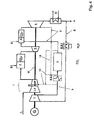
- the process scheme of the embodiment can be seen in Fig. 4 no partial oxidation stage, but the CO 2 -reduced exhaust gas is only used for cooling purposes within the sequential combustion stage 4 and the low-pressure turbine stage 5.
- return lines 13 are provided, via which the recirculated exhaust gas compressed in the exhaust gas compressor unit 7 either directly, cooled or CO 2 -reduced after passing through the CO 2 separation unit 9 of the high-pressure compressor stage HP is supplied for purposes of metered admixture to the supply air L.
- Optionally serves a bypass line 14 for bridging the CO 2 -Abscheideiki 9 of a portion of the compressed and cooled recirculated exhaust gas stream in cases where the recirculated exhaust gas stream exceeds the absorption capacity of the CO 2 -Abscheideappel 9.
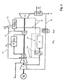
- a further embodiment is shown, which is comparable to the embodiment in Fig. 4 a separate CO 2 -Ver emphasizertre 7 provides, in addition, the sequential combustion takes place by way of partial oxidation, wherein the partial oxidation stage 11 supplied amount of oxygen via a bypass line 15, the downstream of the low-pressure compressor section LP targeted removal of a portion of the precompressed Zu Kunststoff L into the oxidation unit 11 in which the fuel is partially oxidized to release hydrogen. It would also be possible, alternatively or in combination with the bypass line 15 via the supply line 12 from the high-pressure turbine stage third exiting hot gases of the oxidation unit 11 to carry out the partial oxidation of the fuel B to use.
- FIG. 6 A process diagram of such a gas turbine plant is in Fig. 6 shown.
- the gas turbine plant differs according to Fig. 6 in that in addition a second shaft W 'is provided which is driven by a separate gas turbine consisting of the high-pressure turbine part 3' and low-pressure turbine part 5 '.
- the high-pressure turbine part 3 'and the low-pressure turbine part 5' are each charged with hot gases, which respectively emerge from the combustion chambers 2 'and 4'.
- the high-pressure compressor stage HP ' is likewise supplied, like the high-pressure compressor stage HP, from the precompressed supply air L which originates from the low-pressure compressor stage LP of the combustion supply compressor unit 1.
- the recirculated exhaust gas supplied via the recirculation line 6 to the low-pressure compressor stage LP 'of the combustion air-compressor unit 1' and compressed to an intermediate pressure is not mixed with the combustion air, but conducted exclusively via a cooled discharge into the CO 2 separation unit 9.
Landscapes
- Engineering & Computer Science (AREA)
- Chemical & Material Sciences (AREA)
- Combustion & Propulsion (AREA)
- Mechanical Engineering (AREA)
- General Engineering & Computer Science (AREA)
- Chemical Kinetics & Catalysis (AREA)
- Organic Chemistry (AREA)
- General Health & Medical Sciences (AREA)
- Inorganic Chemistry (AREA)
- Health & Medical Sciences (AREA)
- Life Sciences & Earth Sciences (AREA)
- Sustainable Development (AREA)
- Engine Equipment That Uses Special Cycles (AREA)
- Treating Waste Gases (AREA)
Description
- Die Erfindung bezieht sich auf eine Wärmekraftanlage, vorzugsweise eine Gasturbinenanlage, mit sequentieller Verbrennung und reduziertem CO2-Ausstoß, die folgende über jeweils wenigstens einen Strömungskanal in Serie miteinander verbundene Komponenten aufweist: eine Verbrennungszuluft-Kompressoreinheit, eine erste Brennkammer, eine Hochdruckturbinenstufe, eine zweite Brennkammer sowie eine Niederdruckturbinenstufe, wobei die zweite Brennkammer und/oder die Niederdruckturbinenstufe zu Kühlzwecken mit einem Kühlgasstrom versorgbar sind.
US. 6 199 363 B offenbart eine solche Wärmekraftanlage. Ferner wird ein Verfahren zum Betreiben eine Wärmekraftanlage der vorstehenden Art beschrieben. - Im Rahmen des Klimaschutzes sind seit geraumer Zeit Bestrebungen im Gange die Emission von Treibhausgasen, insbesondere von CO2 in die Atmosphäre zu vermindern. Hierzu sind bereits eine Vielzahl von Vorstößen unternommen worden, durch die eine teilweise bis vollständige Abscheidung des bei der Verbrennung fossiler Brennstoffe erzeugten CO2 erreicht wird. Besonderes Interesse gilt dabei der Erzeugung elektrischer Energie durch Befeuerung von Brennkammern zum Antrieb von Gasturbinenanlagen, deren Abgasemissionsvermögen einen nicht unbeträchtlichen Anteil an dem antropogen in die Atmosphäre ausgebrachten Emissionsvolumen ausmacht. Im Bestreben den durch Gasturbinenanlagen verursachten CO2-Austrag in die freie Atmosphäre zu verringern, sind Techniken zur CO2-Abscheidung aus den Abgasströmen von Gasturbinenanlagen bekannt, die im Wege einer Rezirkulation des Abgasstromes eine CO2 Abscheidung unter möglichst hohem Druck bewirken. Grundsätzlich gilt, je höher der CO2-Partialdruck im Abgasstrom, umso besser ist die Effizienz der CO2-Abscheidung. Zur Druckerhöhung des Abgasstromes wird dieser in an sich bekannter Weise mittels der Verbrennungszuluft-Kompressoreinheit der Gasturbinenanlage komprimiert, wobei das rezirkulierte Abgas mit Frischluft verdünnt wird, wodurch einerseits der Sauerstoffgehalt der im Wege der Kompressoreinheit zu verdichtenden Verbrennungszuluft als auch die CO2-Konzentration des rezirkulierten Abgases reduziert werden. Durch den geringeren Sauerstoffgehalt der durch die rezirkulierte Abgasführung entstehenden komprimierten Mischluft, die im weiteren Strömungsverlauf der Gasturbinenanlage dem Brenner zugeführt wird, in dem die Mischluft durch Beimischung von Brennstoff in ein zündfähiges Brennstoff Luftgemisch überführt wird und letztlich in der Brennkammer zur Zündung gebracht wird, kommt es insbesondere in Fällen zu so genannten Verbrennungsinstabilitäten, in denen die Verbrennung innerhalb der Brennkammer ohne jeglichen Sauerstoffüberschuss erfolgt. Derartige Verbrennungsinstabilitäten führen einerseits zu hohen CO-Emissionen und andererseits zur Ausbildung thermoakustischer Schwingungen, die den Betrieb der Gasturbinenanlage stark beeinträchtigen können. Andererseits führt der durch die Mischung mit Verbrennungszuluft verringerte CO2-Gehalt in der rezirkulierten, verdichteten Abgasströmung zu einer geringeren Effizienz der CO2-Abscheidung. Hierzu soll die Erfindung Abhilfe schaffen und einen Weg zum Betreiben von Gasturbinenanlagen aufzeigen, mit dem eine effiziente CO2-Abscheidung aus der rezirkulierten Abgasströmung möglich wird, ohne dabei das stabile Brennerverhalten nachhaltig zu beeinflussen.
- Der Erfindung liegt die Aufgabe zugrunde, eine Wärmekraftanlage vorzugsweise einer Gasturbinenanlage mit sequentieller Verbrennung und reduziertem CO2-Ausstoß gemäß dem Oberbegriff des Anspruches 1 derart weiterzubilden, dass mit einem möglichst geringen, anlagetechnischen Aufwand eine möglichst effiziente CO2-Abscheidung aus dem Abgasstrom einer Gasturbinenanlage möglich wird, ohne dabei das Betriebsverhalten und insbesondere das Emissionsverhalten der Gasturbinenanlage nachhaltig zu beeinträchtigen. Die erfindungsgemäße Maßnahme Soll überdies die Möglichkeit der Retrofitierbarkeit an bereits in Betrieb befindlichen Gasturbinen gestatten. Ferner gilt es, ein entsprechendes Verfahren zum Betreiben einer diesbezüglichen Gasturbinenanlage anzugeben.
- Die Lösung der der Erfindung zugrunde liegenden Aufgabe ist im Anspruch 1 angegeben. Gegenstand des Anspruches 16 ist ein Verfahren zum Betreiben einer Wärmekraftanlage, vorzugsweise Gasturbinenanlage. Den Erfindungsgedanken vorteilhaft weiterbildende Merkmale sind Gegenstand der Unteransprüche und insbesondere der Beschreibung unter Bezugnahme auf die Ausführungsbeispiele zu entnehmen.
- Erfindungsgemäß ist eine Wärmekraftanlage, vorzugsweise Gasturbinenanlage mit sequentieller Verbrennung und reduziertem CO2Ausstoß, die folgende über jeweils wenigstens einen Strömungskanal in Serie miteinander verbundene Komponenten aufweist: eine Verbrennungszuluft-Kompressoreinheit, eine erste Brennkammer, eine Hochdruckturbinenstufe, eine zweite Brennkammer sowie eine Niederdruckturbinenstufe, wobei die zweite Brennkammer und/oder die Niederdruckturbinenstufe zu Kühlzwecken mit einem Kühlgasstrom versorgbar sind, derart weitergebildet, dass eine Rezirkulationsleitung vorgesehen ist, die wenigstens einen Teil eines aus der Niederdruckturbinenstufe austretenden Abgasstromes einer Kühleinheit zuführt. Wenigstens ein Teil des aus der Kühleinheit austretenden komprimierten Abgasstromes wird als Kühlgasstrom über eine Kühlleitung der zweiten Brennkammer und/oder der Niederdruckturbinenstufe zu Kühlzwecken zugeführt, wodurch die mit den innerhalb der zweiten Brennkammer entstehenden Heißgasen exponierten Gasturbinenkomponenten effektiv gekühlt werden können. Überdies ist in der Kühlleitung eine CO2-Abscheideeinheit vorgesehen, die zumindest Teile von CO2 aus dem Kühlgasstrom separiert. Die Erfindung baut somit im Wesentlichen auf einer Gasturbinenanlage mit sequentieller Verbrennung auf, bei der das rezirkulierte Abgas über eine entsprechend vorgesehene Verdichtereinheit auf einen Zwischendruck komprimiert wird, auf dem die CO2-Separation erfolgt und der es überdies gestattet, den CO2 abgereicherten Abgasstrom als Kühlgasstrom auf dem Zwischendruckniveau zu Zwecken der Kühlung in die zweite Brennkammer sowie vorzugsweise auch in die Niederdruckturbinenstufe einzuspeisen. Zu Zwecken einer effektiven Kühlung wird der vorverdichtete, rezirkulierte Abgasstrom vor Eintritt in die CO2-Abscheideeinheit durch einen Kühler geleitet. Der zur Kühlung der zweiten Brennkammer benutzte Teil des Kühlgasstroms wird durch die sequentielle Verbrennung wieder auf die Arbeitstemperatur der Niederdruckturbine erwärmt, wodurch kein Wirkungsgradverlust entsteht. Weitere Einzelheiten können den Ausführungsbeispielen unter Bezugnahme auf die folgenden Figuren entnommen werden.
- In einer bevorzugten Ausführungsform sieht die Befeuerung der zweiten Brennkammer, der so genannten sequentiellen Brennerstufe, den Einsatz einer partiellen Oxidation vor, bei der zur Einstellung einer stöchiometrischen Verbrennung die zweite Brennkammer mit einer Oxidationseinheit kombiniert ist, durch die Brennstoff zur Befeuerung der zweiten Brennkammer wenigstens teilweise unter Freisetzung von Wasserstoff oxidiert wird und zumindest mit dem als Kühlgas dienenden CO2 abgereicherten Abgasstrom unter Ausbildung eines stöchiometrischen Brennstoff-Sauerstoffgemisches zur Zündung gebracht wird. Je nach vorhandenem Sauerstoffgehalt innerhalb des gekühlten, CO2-abgereicherten Abgasstromes kann anteilsmäßig die aus der Hochdruckturbinenstufe austretenden Heißgase dem Kühlgasstrom beigemischt werden. Auch in diesem Zusammenhang stehende, weitere Einzelheiten können den im Weiteren beschriebenen Ausführungsbeispielen entnommen werden.
- Grundsätzlich ist es möglich, die Verdichtung des rezirkulierten Abgasstromes im Rahmen eines Niederdruckkompressorteils der Verbrennungszuluft-Kompressoreinheit vorzunehmen, wobei jedoch eine Zumischung mit Frischluft die Folge ist, mit den eingangs beschriebenen Nachteilen. In einer besonders vorteilhaften Ausführungsform dient eine extra für die Komprimierung des rezirkulierten Abgasstromes vorgesehene Abgasverdichtereinheit zur Drucksteigerung des Abgasstromes auf ein bestimmtes Zwischendruckniveau zur weiteren Einspeisung als Kühlgasströmung in die vorstehend beschriebene sequentielle Verbrennereinheit sowie in die Niederdruckturbinenstufe.
- Somit zeichnet sich das erfindungsgemäße Verfahren zum Betreiben einer Wärmekraftanlage mit sequentieller Verbrennung und reduziertem CO2-Ausstoß dadurch aus, dass wenigstens ein Teil des aus der Niederdruckturbinenstufe austretenden Abgases rezirkuliert, verdichtet und einer CO2-Abscheidung zur Gewinnung von CO2 zugeführt wird und dass der CO2 abgereicherte Abgasstrom zugleich auch als Kühlgasstrom zur Kühlung der zweiten Brennkammer und/oder der Niederdruckturbinenstufe bereitgestellt wird.
- Die Erfindung wird nachstehend ohne Beschränkung des allgemeinen Erfindungsgedankens anhand von Ausführungsbeispielen unter Bezugnahme auf die Zeichnungen exemplarisch beschrieben. Es zeigen:
- Fig. 1
- an sich bekannte Gasturbine mit sequentieller Verbrennung (Stand der Technik),
- Fig. 2-7
- schematisierte Prozessschemata für erfindungsgemäß ausgebildete Gasturbinenanlage mit sequentieller Verbrennung und einem CO2-reduziertem Abgasstrom.
- In
Fig. 1 ist ein schematisiertes vereinfachtes Prozessschema einer an sich bekannten Gasturbinenanlage mit sequentieller Verbrennung dargestellt. Die Gasturbinenanlage besteht im Wesentlichen aus einer Hochdruckturbinenstufe 3 sowie einer Niederdruckturbinenstufe 5 mit einer dazwischen liegenden sequentiellen Verbrennung 4. Zuluft L wird in einer Verbrennungszuluft-Kompressoreinheit 1 über zwei Kompressorstufen LP, HP auf ein hohes Druckniveau verdichtet In einer Standardbrennkammer 2 wird diese Luft mit Brennstoff B vorgemischt und verbrannt. Das in der Brennkammer 3 erzeugte Heißgas wird anschließend in der Hochdruckturbinenstufe 3 auf den Zwischendruck entspannt. Da das aus der ersten mageren Vormischverbrennung stammende Heißgas noch mehr als die Hälfte seines ursprünglichen Sauerstoffgehaltes enthält, wird nochmals Brennstoff B unmittelbar vor einer speziellen sequentiellen Brennkammer 4 zugemischt und zur Zündung gebracht. Dieses nochmals erhitzte Heißgas entspannt sich stromab in einer Niederdruckturbinenstufe 5 auf Atmosphärendruck, wobei letztlich die entspannten Heißgase in Form eines Abgasstromes A in die freie Atmosphäre freigesetzt werden. In besonders vorteilhafter Weise wird ein Teil der in den Niederdruckkompressorteil LP vorverdichteten Verbrennungszuluft abgezweigt und über eine Kühleinheit KA1 gekühlt und zu Kühlzwecken der sequentiellen Brennkammer 4 sowie auch der Niederdruckturbinenstufe 5 zugeleitet - Ausgehend von der vorstehend beschriebenen, an sich bekannten gestuft betriebenen Gasturbinenanlage mit sequentieller Verbrennung wird gemäß Ausführungsbeispiel in
Fig. 2 das aus der Niederdruckturbinenstufe 5 austretende Abgas A über eine Rezirkulationsleitung 6 in den Zuluftstrom der Niederdruckkompressoreinheit 7 rezirkuliert in der das rezirkulierte Abgas mit der Zuluft gemischt und auf ein Zwischendruckniveau verdichtet wird. In vorteilhafter Weise tritt das rezirkulierte Abgas A längs der Rezirkulationsleitung 6 durch eine Wärmetauschereinheit D hindurch, an der ein Wärmeübergang zu einem Dampfkreislauf, beispielsweise zum Antrieb einer nicht weiter dargestellten Dampfturbine, erfolgt. Des Weiteren sieht die Rezirkulationsleitung 6 eine Kühlereinheit KA1 vor, in der zum einen das Abgas gekühlt und im Wege einer Kondensation entfeuchtet wird. - Das durch den Niederdruckkompressorteil LP auf Zwischendruck vorverdichtete Abgas gelangt nun über eine so genannte Kühlleitung 8 in eine CO2-Abscheideeinheit 9, in der aufgrund des vorherrschenden hohen Zwischendruckniveaus eine durchaus effiziente CO2-Abscheidung erfolgt. In vorteilhafter Weise ist stromauf zur CO2-Abscheideeinheit 9 eine weitere Kühlereinheit KA2 vorgesehen. Für die CO2-Abscheideeinheit eignen sich an sich bekannte Abscheidevorrichtungen wie beispielsweise chemische Absorption, z.B. auf Basis von MEA oder physikalisch wirkende Abscheider, z.B. auf Basis von Membranen. Mit Hilfe derartiger CO2-Abscheideeinheiten können CO2-Separatorwirkungen zwischen 70 und 99% erzielt werden. Der aus der CO2-Abscheideeinheit 9 austretende CO2 abgereicherte Abgasstrom wird im Weiteren zu Kühlzwecken der sequentiellen Brennereinheit 4 sowie der Niederdruckturbinenstufe 5 zugeleitet. Wobei der zur Kühlung der zweiten Brennkammer benutzte Teil des Kühlgasstroms durch die sequentielle Verbrennung wieder auf die Arbeitstemperatur der Niederdruckturbine erwärmt wird, wodurch kein Wirkungsgradverlust entsteht.
- Solange die sequentielle Verbrennerstufe 4 mit Sauerstoffüberschuss betrieben wird, bildet sich eine aerodynamisch stabile Vormischflammenfront innerhalb der Brennkammer aus, d.h. der Verbrennungsvorgang erfolgt stabil. Wird jedoch die rezirkulierte Abgasmenge in einem Maße erhöht, bei dem der Sauerstoffgehalt in der der ersten Brennkammer 2 zugeführten, hochverdichteten Verbrennungsluft gerade noch zur vollständigen Verbrennung des zugeführten Brennstoffes B ausreicht, so erfolgt die Verbrennung in der sequentiellen Verbrennerstufe 4 bei einem noch geringeren Eintrittsauerstoffgehalt ohne Sauerstoffüberschuss. Dieser Zustand ist zwar aus Gründen eines besonders hohen CO2-Abscheidegrades bei einer maximal möglichen Abgasrezirkulation besonders wünschenswert. Zudem kommt, dass bei einer derartigen Betriebsweise der minimale Sauerstoffgehalt innerhalb der jeweiligen Verbrennungszonen zu sehr geringen NOx-Emissionswerten führt. Jedoch treten bei diesen Verbrennungsbedingungen erfahrungsgemäß Verbrennungsinstabilitäten auf, beispielsweise in Form thermoakustischer Schwingungen, hohen CO-Emissionen sowie auch dem plötzlichen Verlöschen der Vormischflamme. Um diesen negativen Verbrennungserscheinungen entgegen zu treten und zugleich die beschriebenen Vorteile einer Verbrennung unter stöchiometrischen Sauerstoffbedingungen nutzen zu können, bedient man sich der so genannten partiellen Oxidation. In diesem Zusammenhang sei auf das Ausführungsbeispiel in
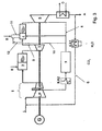
Fig. 3 verwiesen, in dem ein Prozessschema für eine Gasturbinenanlage dargestellt ist, die mit Ausnahme einer an der sequentiellen Verbrennerstufe 4 vorgenommenen Modifikation im Übrigen mit dem inFig. 2 dargestellten Prozessschema identisch ist. Bezüglich Erklärungen von Bezugszeichen, die bereits inFig. 2 erläutert worden sind, wird, um Wiederholungen zu vermeiden, auf das entsprechende vorstehende Ausführungsbeispiel verwiesen. - Es sei im Weiteren angenommen, dass die Beimischung des rezirkulierten Abgases in die Verbrennungszuluft L in einem Maße erfolgt, bei dem der Sauerstoffgehalt in der Zuluft der Brennkammer 2 gerade noch zur Verbrennung des zugeführten Brennstoffes B ausreicht. Wie vorstehend erläutert erfolgt die sequentielle Verbrennung in der Brennkammer 4 unter Sauerstoffmangel. Um die damit verbundenen, vorstehend beschriebenen Nachteile zu vermeiden, wird Brennstoff B zunächst unter Sauerstoffmangel im Rahmen einer so genannten Oxidationseinheit 11 zur Reaktion gebracht. Die Oxidationseinheit 11 ist in vorteilhafter Weise als Katalysatoreinheit ausgeführt, der zum einen der zu oxidierende Brennstoff B und zum anderen eine Sauerstoffmenge im Bereich zwischen 20 und 75% des theoretischen Sauerstoffbedarfes für eine vollständige Oxidation des Brennstoffes zugeführt wird. Die zugeführte Sauerstoffmenge erfolgt über die Zuleitung 10, die einen Teil des COrabgereicherten Abgases aus der Kühlleitung 8 abzweigt. Sollte der im CO2-abgereicherten Abgasstrom enthaltene Sauerstoffgehalt nicht den geforderten Sauerstoffgehalt zur Durchführung einer partiellen Oxidation entsprechen, so können zusätzlich Teile des aus der Hochdruckturbinenstufe 3 austretenden Heißgase über die Zuleitung 12 im CO2-abgereicherten Abgasstrom zur Einspeisung in die Oxidationsstufe 11 beigemischt werden.
- Durch die partielle Oxidation innerhalb der Oxidationsstufe 11 wird aus den Kohlenwasserstoffverbindungen des Brennstoffes B ein Teil des Wasserstoffes abgetrennt und liegt nach der partiellen Oxidationsstufe 11 als freier Wasserstoff in der heißen Austrittsmischung vor Eintritt in die sequentielle Brennstufe 4 vor. Werden nun die aus der Hochdruckturbinenstufe 3 austretenden Heißgase mit dieser Wasserstoffanteile enthaltenden Gasmischung der sequentiellen Brennstufe 4 zugeführt, so kommt es durch die hohe Temperatur und die hohe Reaktivität des enthaltenen Wasserstoffes zu einer spontanen Reaktion und dem vollständigen Ausbrand des in Form von Wasserstoff, CO und restlichen Kohlenwasserstoffen noch vorhandenen Brennstoffes. In besonders vorteilhafter Weise führt die hohe Reaktivität des Brennergemisches zu einer sich stabil ausbildenden Verbrennung innerhalb der sequentiellen Brennstufe 4, so dass die eingangs erwähnten Nachteile hinsichtlich des Auftretens von thermoakustischen Schwingungen, hohen CO-Emissionen sowie dem Verlöschen der Vormischbrennerflamme vollständig vermieden werden können.
- In einer vorteilhaften Ausführungsform zur Durchführung der partiellen Oxidation eignet sich der Einsatz einer Brennstoffzuführungslanze innerhalb der sequentiellen Brennstufe 4, innerhalb der die zur Freisetzung von Wasserstoff erforderliche Reaktion des zugeführten Brennstoffes B durch den Einsatz eines Katalysators erfolgt.
- Zwar dienen die vorstehend beschriebenen Maßnahmen zur Optimierung der in den Brennkammern 2 und 4 erfolgenden Verbrennungsprozesse, doch gilt es erfindungsgemäß in erster Linie, den CO2-Gehalt der von der Gasturbinenanlage freigesetzten Abgase zu reduzieren. Die erfindungsgemäß in die Kühlleitung 8 eingesetzte CO2-Abscheideeinheit 9 arbeitet umso effektiver, je größer die der Abscheideeinheit zugeführte CO2-Konzentration in der Zuströmung ist. Um hierfür Sorge zu tragen, erfolgt in den Ausführungsbeispielen gemäß der
Fig. 2 und3 eine Vorverdichtung des rezirkulierten Abgases mittels des Niederdruckkompressorteils LP der Verbrennungszuluft-Kompressoreinheit 1. Nachteilhaft bei dieser Ausführungsform ist es jedoch, dass das rezirkulierte Abgas mit der zugeführten Zuluft L vermischt und somit gemeinsam innerhalb des Niederdruckkompressorteils LP verdichtet wird. Somit gelangt ein verdünnter, vorverdichteter Abgasstrom in die CO2-Abscheideeinheit 9. Um diesen "Verdünnungseffekt" zu vermeiden, wird unter Bezugnahme auf das Ausführungsbeispiel inFig. 4 vorgeschlagen, einen separaten Kompressor für das rezirkulierte Abgas zu verwenden. Hierzu ist auf einer gemeinsamen Welle W, längs der der Verbrennungszuluft-Kompressoreinheit 1 sowie die Hoch- und Niederdruckturbinenstufe 3, 5 angeordnet sind, eine separate Abgasverdichtereinheit 7 vorgesehen, in der ausschließlich das rezirkulierte Abgas über die Rezirkulationsleitung 6 komprimiert und über die Kühlereinheit KA2 der CO2-Abscheideeinheit 9 zugeführt wird. Auf diese Weise bleibt die hohe CO2-Konzentration im Abgas erhalten, wodurch eine Effizienzsteigerung der CO2-Abscheideeinheit 9 erzielt werden kann. Im Falle einer stöchiometrischen Betriebsweise des Verbrennungsprozesses, wie vorstehend beschrieben, enthält das Abgas keinen Sauerstoff mehr und kann infolgedessen auch nicht mehr zur Verbrennung, beispielsweise im Wege einer partiellen Oxidation, genutzt werden. Somit sieht das Prozessschema des Ausführungsbeispiels inFig. 4 keine partielle Oxidationsstufe vor, vielmehr wird das CO2-reduzierte Abgas nur noch zu Kühlzwecken innerhalb der sequentiellen Verbrennerstufe 4 sowie der Niederdruckturbinenstufe 5 genutzt. Zur Einstellung der stöchiometrischen Betriebsweise der Verbrennungsprozesse innerhalb der Brennkammern 2, 4 sind Rückführleitungen 13 vorgesehen, über die das im Rahmen der Abgasverdichtereinheit 7 komprimierte rezirkulierte Abgas entweder direkt, gekühlt oder CO2-reduziert nach Durchtritt durch die CO2-Abscheideeinheit 9 der Hochdruckkompressorstufe HP zugeführt wird, zu Zwecken einer dosierten Beimischung zur Zuluft L. - Optional dient eine Umgehungsleitung 14 zur Überbrückung der CO2-Abscheideeinheit 9 eines Teils des verdichteten und gekühlten rezirkulierten Abgasstromes in Fällen, in denen der rezirkulierte Abgasstrom die Aufnahmekapazität der CO2-Abscheideeinheit 9 übersteigt.
- In
Fig. 5 ist ein weiteres Ausführungsbeispiel dargestellt, das vergleichbar mit dem Ausführungsbeispiel inFig. 4 eine separate CO2-Verdichterstufe 7 vorsieht, zusätzlich erfolgt die sequentielle Verbrennung im Wege einer partiellen Oxidation, wobei die der partiellen Oxidationsstufe 11 zugeführte Sauerstoffmenge über eine Bypassleitung 15 erfolgt, die stromab zum Niederdruck-Kompressorteil LP eine gezielte Ableitung eines Teils der vorkomprimierten Zuluft L in die Oxidationseinheit 11 ermöglicht, in der der Brennstoff unter Freisetzung von Wasserstoff partiell oxidiert wird. Ebenso wäre es möglich, alternativ oder in Kombination zur Bypassleitung 15 über die Zuleitung 12 aus der Hochdruckturbinenstufe 3 austretende Heißgase der Oxidationseinheit 11 zur Durchführung der partiellen Oxidation des Brennstoffes B zu nutzen. - Alle vorstehend beschriebenen Ausführungsbeispiele betreffen Gasturbinenanlagen, längs deren einzige Welle W die Generatoreinheit G, die Verbrennungszuluft-Kompressoreinheit 1 sowie die Hochdruckturbinenstufe 3 und Niederdruckturbinenstufe 5 angeordnet sind. In Fällen, in denen das rezirkulierte Abgas in einer separaten Abgasverdichtereinheit 7 komprimiert wird, ist auch diese längs der gemeinsamen Welle W angebracht.
- Nicht zuletzt aus Gründen einer leichteren Retrofitierbarkeit der erfindungsgemäßen Maßnahme an bereits in Betrieb befindlichen Gasturbinenanlagen, bietet es sich an, die Verdichtereinheit, mit der das rezirkulierte Abgas komprimiert wird, auf einer getrennt angetriebenen Welle anzubringen. Ein Prozessschema einer derartigen Gasturbinenanlage ist in
Fig. 6 dargestellt. Legt man zunächst einmal das inFig. 2 beschriebene Prozessschema zugrunde, so unterscheidet sich die Gasturbinenanlage gemäßFig. 6 dadurch, dass zusätzlich eine zweite Welle W' vorgesehen ist, die von einer getrennten Gasturbine, bestehend aus dem Hochdruckturbinenteil 3' und Niederdruckturbinenteil 5' angetrieben wird. Der Hochdruckturbinenteil 3' sowie Niederdruckturbinenteil 5' wird jeweils mit Heißgasen beschickt, die jeweils aus den Brennkammern 2' und 4' austreten. Zur Versorgung der Brennkammern 2' und 4' mit der für die Verbrennung erforderlichen Verbrennungszuluft wird die Hochdruckkompressorstufe HP' gleichfalls wie die Hochdruckkompressorstufe HP von der vorkomprimierten Zuluft L, die aus der Niederdruckkompressorstufe LP der Verbrennungszuluft-Kompressoreinheit 1 herrührt, versorgt. Hingegen wird das rezirkulierte Abgas, das über die Rezirkulationsleitung 6 der Niederdruckkompressorstufe LP' der Verbrennungszuluft-Kompressoreinheit 1' zugeführt und auf einen Zwischendruck komprimiert wird nicht der Verbrennungszuluft beigemischt, sondern ausschließlich über eine gekühlte Ableitung in die CO2-Abscheideeinheit 9 geleitet. - Durch die getrennte Kompression des rezirkulierten Abgases im Rahmen der Niederdruckkompressorstufe LP' wird der CO2-Abscheideeinheit ein hoch verdichteter und vor allem konzentrationsreicher CO2-Abgasstrom zugeführt, aus dem höchst effizient CO2 abgeschieden werden kann. Der deutlich an CO2-reduzierte Abgasstrom wird ebenfalls, wie bereits in den vorstehenden Ausführungsbeispielen beschrieben, zu Kühlzwecken der sequentiellen Brennkammer 4 sowie 4' sowie auch den Niederdruckturbinenstufen 5 sowie auch 5' zugeführt.
- Mit Hilfe der in
Fig. 6 dargestellten Gasturbinenanlage kann der CO2-Anteil des aus der Gasturbinenanlage austretenden Abgasstrom A zwar deutlich reduziert werden, eine vollständige CO2-Separation aus dem in die freie Atmosphäre austretenden Abgasstromes ist jedoch systembedingt nicht möglich. Dies liegt daran, dass Abgasanteile aus der Niederdruckturbinenstufe 5 im Abgasstrom A enthalten sind, die aufgrund fehlender Rezirkulation im Abgasstrom verbleiben. Um jedoch auch diese Anteile möglichst gering zu halten, sieht das letzte Ausführungsbeispiel gemäßFig. 7 den Einsatz der partiellen Oxidation vor. Das inFig. 7 dargestellte Prozessschema ist eine Weiterbildung des inFig. 6 dargestellten Prozessschemas im Sinne der unter Bezugnahme aufFig. 5 beschriebenen partiellen Oxidation. Auch im Ausführungsbeispiel gemäßFig. 7 dient die Bypassleitung 15, 15' zur gezielten Sauerstoffzufuhr im Rahmen zwischen 20 und 75% des theoretischen Sauerstoffbedarfes für eine vollständige Oxidation, die in Verbindung mit der Wasserstofffreisetzung bedingt durch die katalytische Brennstoffumsetzung zu einem reaktiven, zündfähigen Gemisch führt, das einen stabilen Verbrennungsprozess gewährleistet. -
- 1,1'
- Verbrennungszuluft-Kompressoreinheit
- 2, 2'
- Erste Brennkammer
- 3, 3'
- Hochdruckturbinenstufe
- 4, 4'
- Zweite Brennkammer, sequentielle Brennkammer
- 5, 5'
- Niederdruckturbinenstufe
- 6
- Rezirkulationsleitung
- 7
- Verdichtereinheit
- 8
- Kühlleitung
- 9
- CO2-Abscheideeinheit
- 10
- Ableitung
- 11
- Oxidationseinheit
- 12
- Ableitung
- 13
- Rückführleitung
- 14
- Umgehungsleitung
- 15
- Bypassleitung
- A
- Abgas
- D
- Wärmetauschereinsheit
- KA1, KA2
- Kühlereinheit
- G
- Generator
- LP, LP'
- Niederdruckkompressorstufe
- HP, HP'
- Hochdruckkompressorstufe
- B
- Brennstoff
- L
- Zuluft
- S
- Heißgasströmung
- W, W'
- Welle
Claims (25)
- Wärmekraftanlage mit sequentieller Verbrennung und reduziertem CO2-Ausstoß, die folgende über jeweils wenigstens einen Strömungskanal (S) in Serie miteinander verbundene Komponenten aufweist:eine Verbrennungszuluft-Kompressoreinheit (1), eine erste Brennkammer (2), eine Hochdruckturbinenstufe (3), eine zweite Brennkammer (4) sowie eine Niederdruckturbinenstufe (5), wobei die zweite Brennkammer (4) und/oder die Niederdruckturbinenstufe (5) zu Kühlzwecken mit einem Kühlgasstrom versorgbar sind,dadurch gekennzeichnet, dass eine Rezirkulationsleitung (6) vorgesehen ist, die wenigstens einen Teil eines aus der Niederdruckturbinenstufe (5) austretenden Abgasstroms einer Verdichtereinheit (7) zuführt,dass eine Kühlleitung (8) vorgesehen ist, die wenigstens einen Teil des aus der Verdichtereinheit (7) austretenden komprimierten Abgasstroms als Kühlgasstrom der zweiten Brennkammer (4) und/oder der Niederdruckturbinenstufe (5) zu Kühlzwecken zuführt, unddass in der Kühlleitung (8) eine CO2-Abscheideeinheit (9) vorgesehen ist, die zumindest Anteile von CO2 aus dem Kühlgasstrom separiert.
- Wärmekraftanlage nach Anspruch 1,
dadurch gekennzeichnet, dass in der Kühlleitung (8) nach der Verdichtereinheit (7) und vor der CO2-Abscheideeinheit (9) eine Kühleinheit KA2 vorgesehen ist. - Wärmekraftanlage nach Anspruch 1 oder 2,
dadurch gekennzeichnet, dass die Verbrennungszuluft-Kompressoreinheit (1) eine wenigstens zweistufige Kompressoreinheit ist, die einen Niederdruck- (LP) und einen Hochdruck-(HP) Kompressorteil aufweist, und
dass die Verdichtereinheit (7) dem Niederdruck-Kompressorteil (LP) der Verbrennungszuluft-Kompressoreinheit (1) entspricht - Wärmekraftanlage nach einem der Ansprüche 1 bis 3,
dadurch gekennzeichnet, dass stromab der CO2-Separationseinheit (9) die Kühlleitung (8) eine Ableitung (10) vorsieht, die mit einer Oxidationseinheit (11) verbunden ist, durch die Brennstoff zur Befeuerung der zweiten Brennkammer (4) unter Freisetzung von Wasserstoff partiell oxidiert wird, bevor der partiell oxidierte Brennstoff innerhalb der zweiten Brennkammer zur Zündung gebracht wird. - Wärmekraftanlage nach Anspruch 4,
dadurch gekennzeichnet, dass zwischen der Hochdruckturbinenstufe (3) und der zweiten Brennkammer (4) eine Ableitung (12) im Strömungskanal (S) vorgesehen ist, die vor Eintritt in die Oxidationseinheit (11) in die Ableitung (10) mündet. - Wärmekraftanlage nach einem der Ansprüche 1 bis 5,
dadurch gekennzeichnet, dass die Verdichtereinheit (7), die Verbrennungszuluft-Kompressoreinheit (1), die Hoch- (3) und Niederdruckturbinenstufe (5) sowie ein Generator (G) auf einer gemeinsamen Welle (W) angeordnet sind. - Wärmekraftanlage nach einem der Ansprüche 1 bis 6,
dadurch gekennzeichnet, dass die Verbrennungszuluft-Kompressoreinheit (1) eine wenigstens zweistufige Kompressoreinheit ist, die einen Niederdruck- (LP) und einen Hochdruck-Kompressorteil (HP) aufweist, und dass in der Kühlleitung (8) stromauf und/oder stromab zur CO2-Abscheideeinheit (9) wenigstens eine Rückführleitung (13) vorgesehen ist, die in den Hochdruck-Kompressorteil (HP) mündet. - Wärmekraftanlage nach einem der Ansprüche 1 bis 7,
dadurch gekennzeichnet, dass in der Kühlleitung (8) eine die CO2-Abscheideeinheit (9) überbrückende Umgehungsleitung (14) vorgesehen ist. - Wärmekraftanlage nach einem der Ansprüche 4 bis 8,
dadurch gekennzeichnet, dass stromab zum Niederdruck-Kompressorteil (LP) eine Bypassleitung (15) vorgesehen ist, die mit einer Oxidationseinheit (11) verbunden ist, durch die Brennstoff zur Befeuerung der zweiten Brennkammer (4) wenigstens teilweise oxidiert wird, bevor der teilweise oxidierte Brennstoff innerhalb der zweiten Brennkammer zur Zündung gebracht wird. - Wärmekraftanlage nach einem der Ansprüche 1 bis 9,
dadurch gekennzeichnet, dass längs der Rezirkulationsleitung (6) eine Kühleinheit (KA1) vorgesehen ist, die Wasser aus dem Abgasstrom ausscheidet. - Wärmekraftanlage nach einem der Ansprüche 1 bis 10,
dadurch gekennzeichnet, dass längs der Rezirkulationsleitung (6) unmittelbar stromab der Niederdruckturbinenstufe (5) eine Wärmetauschereinheit D vorgesehen ist, zur Wärmeabgabe an einen Dampfkreislauf. - Wärmekraftanlage nach einem der Ansprüche 1 bis 11,
dadurch gekennzeichnet, dass die Wärmekraftanlage eine gestuft betriebene Gasturbinenanlage ist. - Wärmekraftantage nach einem der Ansprüche 1 bis 5 oder 7 bis 12,
dadurch gekennzeichnet, dass die Verbrennungszuluft-Kompressoreinheit (1), die Hoch- (3) und Niederdruckturbinenstufe (5) sowie ein Generator (G) auf einer gemeinsamen ersten Welle (W) und die Verdichtereinheit (7) auf einer zweiten, angetriebenen Welle angeordnet sind. - Wärmekraftanlage nach Anspruch 13,
dadurch gekennzeichnet, dass längs der zweiten Welle eine weitere Verbrennungszuluft-Kompressoreinheit (1'), eine weitere Hoch- (3') und Niederdruckturbinenstufe (5') sowie ein weiterer Generator (G') angeordnet sind. - Wärmekraftanlage nach Anspruch 14,
dadurch gekennzeichnet, dass die weitere Verbrennungszuluft-Kompressoreinheit (1'), die weitere Hoch- (3') und Niederdruckturbinenstufe (5') sowie der weitere Generator (G') in analoger Weise angeordnet und mit einander verschaltet sind, wie die Verbrennungszuluft-Kompressoreinheit (1), die Hoch- (3) und Niederdruckturbinenstufe (5) sowie der Generator (G) nach einem der Ansprüche 1 bis 12. - Verfahren zum Betreiben einer Wärmekraftanlage mit sequentieller Verbrennung und reduziertem CO2-Ausstoß, die folgende über jeweils wenigstens einen Strömungskanal (S) in Serie miteinander verbundene Komponenten aufweist: eine Verbrennungszuluft-Kompressoreinheit (1), eine erste Brennkammer (2), eine Hochdruckturbinenstufe (3), eine zweite Brennkammer (4) sowie eine Niederdruckturbinenstufe (5), wobei die zweite Brennkammer (4) und/oder die Niederdruckturbinenstufe (5) zu Kühlzwecken mit einem Kühlgasstrom versorgt wird, dadurch gekennzeichnet, dass wenigstens ein Teil des aus der Niederdruckturbinenstufe austretenden Abgases rezirkuliert, verdichtet und einer CO2-Abscheidung, zur Gewinnung von CO2 zugeführt wird und dass der CO2 abgereicherte Abgasstrom als Kühlgasstrom zur Kühlung der zweiten Brennkammer und/oder der Niederdruckturbinenstufe bereitgestellt wird.
- Verfahren nach Anspruch 16,
dadurch gekennzeichnet, dass das aus der Niederdruckturbinenstufe (5) austretende Abgas einem Wärmtauscher D zur thermischen Kopplung eines Dampfkreislaufes und/oder einer Kühleinheit (KA1) zugeführt wird bevor das rezirkulierte Abgas verdichtet wird. - Verfahren nach einem der Ansprüche 16 bis 17,
dadurch gekennzeichnet, dass das rezirkulierte Abgas zur Verdichtung gemeinsam mit der Verbrennungszuluft in die Verbrennungszuluft-Kompressoreinheit (1) eingeleitet wird. - Verfahren nach Anspruch 18,
dadurch gekennzeichnet, dass die Verdichtung gestuft erfolgt, und
dass nach Erreichen einer ersten Verdichtungsstufe ein Teil des vorverdichteten Abgas-/Verbrennungszutuft-Gemisches abgezweigt, gekühlt und der CO2-Abscheidung zugeführt wird. - Verfahren nach einem der Ansprüche 16 bis 19,
dadurch gekennzeichnet, dass ein Teil des CO2 abgereicherten Abgasstroms mit Brennstoff gemischt wird, wobei wenigsten Teile des Brennstoffes unter Bildung von Wasserstoff oxidiert werden, bevor das Gemisch aus CO2 abgereicherten Abgas und teiloxidiertem Brennstoff in der zweiten Brennkammer zur Zündung gebracht wird. - Verfahren nach Anspruch 20,
dadurch gekennzeichnet, dass ein Teil eines aus der Hochdruckturbinenstufe (3) austretenden Heissgasstromes (S) mit dem CO2 abgereicherten Muss folgerichtig "abgereicherten" heissen Abgasstrom vermischt wird, und
dass das Gemisch aus dem Heissgasstrom und dem CO2 abgereicherten Abgasstrom mit Brennstoff gemischt und anschließend unter Freisetzung von Wasserstoff partiell oxidiert wird. - Verfahren nach Anspruch 20 oder 21,
dadurch gekennzeichnet, dass das Gemisch aus CO2 abgereicherten Abgas und dem teiloxidierten Brennstoff derart gewählt wird, dass der vorhandene Sauerstoffanteil etwa 20 % bis 75 % des theoretischen Sauerstoffbedarf für eine vollständige Verbrennung entspricht. - Verfahren nach einem der Ansprüche 16 bis 17,
dadurch gekennzeichnet, dass das rezirkulierte Abgas separat zur Verbrermungszuluft verdichtet, gekühlt und der CO2-Abscheidung zugeführt wird. - Verfahren nach Anspruch 23,
dadurch gekennzeichnet, dass das verdichtete Abgas, das verdichtete gekühlte Abgas oder das verdichtete, gekühlte und CO2 abgereicherte Abgase zumindest teilweise der vorverdichten Verbrennungszuluft beigemischt wird. - Verfahren nach Anspruch 24,
dadurch gekennzeichnet, dass ein Teil der vorverdichteten Verbrennungszuluft mit Brennstoff gemischt wird, wobei wenigsten Teile des Brennstoffes unter Bildung von Wasserstoff oxidiert werden, bevor das Gemisch aus CO2 abgereicherten Abgas und teiloxidierten Brennstoff in der zweiten Brennkammer zur Zündung gebracht wird.
Applications Claiming Priority (2)
| Application Number | Priority Date | Filing Date | Title |
|---|---|---|---|
| DE10360951A DE10360951A1 (de) | 2003-12-23 | 2003-12-23 | Wärmekraftanlage mit sequentieller Verbrennung und reduziertem CO2-Ausstoß sowie Verfahren zum Betreiben einer derartigen Anlage |
| PCT/EP2004/053123 WO2005064232A1 (de) | 2003-12-23 | 2004-11-26 | Wärmekraftanlage mit sequentieller verbrennung und reduziertem co2-ausstoss sowie verfahren zum bertreiben einer derartigen anlage |
Publications (2)
| Publication Number | Publication Date |
|---|---|
| EP1702176A1 EP1702176A1 (de) | 2006-09-20 |
| EP1702176B1 true EP1702176B1 (de) | 2012-03-14 |
Family
ID=34706527
Family Applications (1)
| Application Number | Title | Priority Date | Filing Date |
|---|---|---|---|
| EP04820847A Expired - Lifetime EP1702176B1 (de) | 2003-12-23 | 2004-11-26 | Wärmekraftanlage mit sequentieller verbrennung und reduziertem co2-ausstoss sowie verfahren zum betreiben einer derartigen anlage |
Country Status (8)
| Country | Link |
|---|---|
| US (1) | US7503178B2 (de) |
| EP (1) | EP1702176B1 (de) |
| CN (1) | CN100561046C (de) |
| AT (1) | ATE549577T1 (de) |
| CA (1) | CA2550675A1 (de) |
| DE (1) | DE10360951A1 (de) |
| NO (1) | NO338858B1 (de) |
| WO (1) | WO2005064232A1 (de) |
Families Citing this family (206)
| Publication number | Priority date | Publication date | Assignee | Title |
|---|---|---|---|---|
| DE102004039164A1 (de) * | 2004-08-11 | 2006-03-02 | Alstom Technology Ltd | Verfahren zur Erzeugung von Energie in einer eine Gasturbine umfassenden Energieerzeugungsanlage sowie Energieerzeugungsanlage zur Durchführung des Verfahrens |
| DE102005015151A1 (de) | 2005-03-31 | 2006-10-26 | Alstom Technology Ltd. | Gasturbinenanlage |
| FR2891013B1 (fr) * | 2005-09-16 | 2011-01-14 | Inst Francais Du Petrole | Production d'energie par turbine a gaz sans emission de c02 |
| FR2900061B1 (fr) * | 2006-04-21 | 2008-07-04 | Inst Francais Du Petrole | Procede pour concentrer le dioxyde de carbone present dans des fumees rejetees par une installation de generation d'energie. |
| WO2007141101A1 (de) * | 2006-06-07 | 2007-12-13 | Alstom Technology Ltd | Verfahren zum betrieb einer gasturbine, anwendung des verfahrens in einem kombikraftwerk und kombikraftwerk zur durchführung des verfahrens |
| US7942008B2 (en) | 2006-10-09 | 2011-05-17 | General Electric Company | Method and system for reducing power plant emissions |
| ATE540213T1 (de) * | 2006-10-16 | 2012-01-15 | Alstom Technology Ltd | Verfahren zum betrieb einer gasturbinenanlage |
| US7739864B2 (en) * | 2006-11-07 | 2010-06-22 | General Electric Company | Systems and methods for power generation with carbon dioxide isolation |
| US7827778B2 (en) * | 2006-11-07 | 2010-11-09 | General Electric Company | Power plants that utilize gas turbines for power generation and processes for lowering CO2 emissions |
| CN100462630C (zh) * | 2007-02-14 | 2009-02-18 | 西安交通大学 | 多级高效环保型燃气轮机气体燃料分级燃烧方法及系统 |
| JP5473610B2 (ja) * | 2007-02-14 | 2014-04-16 | アルストム テクノロジー リミテッド | 発電装置および発電装置の駆動方法 |
| EP2118449B1 (de) * | 2007-02-14 | 2018-11-28 | General Electric Technology GmbH | Kraftwerksanlage mit einem verbraucher sowie verfahren zu deren betrieb |
| EP2158388B1 (de) | 2007-06-19 | 2019-09-11 | Ansaldo Energia IP UK Limited | Gasturbinenanlage mit abgasrezirkulation |
| DE102008002610A1 (de) | 2007-07-11 | 2009-01-15 | Alstom Technology Ltd. | Verfahren zur (Online-) Betriebsüberwachung und Regelung einer Gasturbinenanlage |
| US8393160B2 (en) | 2007-10-23 | 2013-03-12 | Flex Power Generation, Inc. | Managing leaks in a gas turbine system |
| US8671658B2 (en) | 2007-10-23 | 2014-03-18 | Ener-Core Power, Inc. | Oxidizing fuel |
| NO328975B1 (no) * | 2008-02-28 | 2010-07-05 | Sargas As | Gasskraftverk med CO2-rensing |
| CN105587351B (zh) * | 2008-03-25 | 2018-12-21 | 通用电器技术有限公司 | 发电站设备及其运行方法 |
| MY156350A (en) | 2008-03-28 | 2016-02-15 | Exxonmobil Upstream Res Co | Low emission power generation and hydrocarbon recovery systems and methods |
| CA2718803C (en) | 2008-03-28 | 2016-07-12 | Exxonmobil Upstream Research Company | Low emission power generation and hydrocarbon recovery systems and methods |
| US8397482B2 (en) * | 2008-05-15 | 2013-03-19 | General Electric Company | Dry 3-way catalytic reduction of gas turbine NOx |
| US8220271B2 (en) * | 2008-09-30 | 2012-07-17 | Alstom Technology Ltd. | Fuel lance for a gas turbine engine including outer helical grooves |
| US8220269B2 (en) * | 2008-09-30 | 2012-07-17 | Alstom Technology Ltd. | Combustor for a gas turbine engine with effusion cooled baffle |
| PL2344738T3 (pl) | 2008-10-14 | 2019-09-30 | Exxonmobil Upstream Research Company | Sposób i układ do sterowania produktami spalania |
| CH699804A1 (de) * | 2008-10-29 | 2010-04-30 | Alstom Technology Ltd | Gasturbinenanlage mit Abgasrückführung sowie Verfahren zum Betrieb einer solchen Anlage. |
| US20100107592A1 (en) * | 2008-11-04 | 2010-05-06 | General Electric Company | System and method for reducing corrosion in a gas turbine system |
| US8701413B2 (en) | 2008-12-08 | 2014-04-22 | Ener-Core Power, Inc. | Oxidizing fuel in multiple operating modes |
| EP2248999A1 (de) * | 2008-12-24 | 2010-11-10 | Alstom Technology Ltd | Kraftwerk mit CO2-Abscheidung |
| US8621869B2 (en) | 2009-05-01 | 2014-01-07 | Ener-Core Power, Inc. | Heating a reaction chamber |
| EA025821B1 (ru) | 2009-06-05 | 2017-02-28 | Эксонмобил Апстрим Рисерч Компани | Топочная система и способы ее применения |
| US20120174622A1 (en) * | 2009-07-13 | 2012-07-12 | Alstom Technology Ltd | System for gas processing |
| EP2287456A1 (de) * | 2009-08-17 | 2011-02-23 | Alstom Technology Ltd | Gasturbine und Verfahren zum Betrieb der Gasturbine |
| US8171718B2 (en) * | 2009-10-05 | 2012-05-08 | General Electric Company | Methods and systems involving carbon sequestration and engines |
| US20110085955A1 (en) * | 2009-10-12 | 2011-04-14 | Alstom Technology Ltd | System and method for reducing no2 poisoning |
| CA2777768C (en) | 2009-11-12 | 2016-06-07 | Exxonmobil Upstream Research Company | Low emission power generation and hydrocarbon recovery systems and methods |
| GB0920094D0 (en) * | 2009-11-17 | 2009-12-30 | Alstom Technology Ltd | Reheat combustor for a gas turbine engine |
| US20110138766A1 (en) * | 2009-12-15 | 2011-06-16 | General Electric Company | System and method of improving emission performance of a gas turbine |
| EP2348256A1 (de) | 2010-01-26 | 2011-07-27 | Alstom Technology Ltd | Verfahren zum Betreiben einer Gasturbine und Gasturbine |
| WO2011116010A1 (en) | 2010-03-15 | 2011-09-22 | Flexenergy, Inc. | Processing fuel and water |
| DE102011102720B4 (de) | 2010-05-26 | 2021-10-28 | Ansaldo Energia Switzerland AG | Kraftwerk mit kombiniertem Zyklus und mit Abgasrückführung |
| CH704118A1 (de) * | 2010-11-17 | 2012-05-31 | Alstom Technology Ltd | Verfahren zum Betreiben eines Kraftwerks mit kombiniertem Zyklus und mit Abgasrückführung. |
| CH703218A1 (de) | 2010-05-26 | 2011-11-30 | Alstom Technology Ltd | Verfahren zum Betreiben eines Gas-und-Dampf-Kombikraftwerk mit Rauchgasrezirkulation sowie Kraftwerk. |
| WO2011156680A2 (en) | 2010-06-11 | 2011-12-15 | Leva Energy, Inc. | Integrated engine exhaust and heat process flexible and low emission combined heat and power process and system |
| JP5535782B2 (ja) * | 2010-06-16 | 2014-07-02 | 三菱重工業株式会社 | 燃焼システム |
| MY156099A (en) | 2010-07-02 | 2016-01-15 | Exxonmobil Upstream Res Co | Systems and methods for controlling combustion of a fuel |
| CA2801476C (en) * | 2010-07-02 | 2017-08-15 | Exxonmobil Upstream Research Company | Low emission triple-cycle power generation systems and methods |
| CN102959202B (zh) | 2010-07-02 | 2016-08-03 | 埃克森美孚上游研究公司 | 集成系统、发电的方法和联合循环发电系统 |
| US9903271B2 (en) | 2010-07-02 | 2018-02-27 | Exxonmobil Upstream Research Company | Low emission triple-cycle power generation and CO2 separation systems and methods |
| CA2801499C (en) | 2010-07-02 | 2017-01-03 | Exxonmobil Upstream Research Company | Low emission power generation systems and methods |
| JP5906555B2 (ja) | 2010-07-02 | 2016-04-20 | エクソンモービル アップストリーム リサーチ カンパニー | 排ガス再循環方式によるリッチエアの化学量論的燃焼 |
| WO2012018457A1 (en) | 2010-08-06 | 2012-02-09 | Exxonmobil Upstream Research Company | Systems and methods for optimizing stoichiometric combustion |
| WO2012018458A1 (en) | 2010-08-06 | 2012-02-09 | Exxonmobil Upstream Research Company | System and method for exhaust gas extraction |
| US8978380B2 (en) | 2010-08-10 | 2015-03-17 | Dresser-Rand Company | Adiabatic compressed air energy storage process |
| CN102330573A (zh) * | 2010-10-22 | 2012-01-25 | 靳北彪 | 有压气体涡轮增压系统 |
| US20120151935A1 (en) * | 2010-12-17 | 2012-06-21 | General Electric Company | Gas turbine engine and method of operating thereof |
| WO2012088516A2 (en) * | 2010-12-23 | 2012-06-28 | Michael Gurin | Top cycle power generation with high radiant and emissivity exhaust |
| TWI564474B (zh) * | 2011-03-22 | 2017-01-01 | 艾克頌美孚上游研究公司 | 於渦輪系統中控制化學計量燃燒的整合系統和使用彼之產生動力的方法 |
| TWI563165B (en) | 2011-03-22 | 2016-12-21 | Exxonmobil Upstream Res Co | Power generation system and method for generating power |
| TWI563166B (en) | 2011-03-22 | 2016-12-21 | Exxonmobil Upstream Res Co | Integrated generation systems and methods for generating power |
| TWI593872B (zh) | 2011-03-22 | 2017-08-01 | 艾克頌美孚上游研究公司 | 整合系統及產生動力之方法 |
| US9057028B2 (en) | 2011-05-25 | 2015-06-16 | Ener-Core Power, Inc. | Gasifier power plant and management of wastes |
| US20120023954A1 (en) * | 2011-08-25 | 2012-02-02 | General Electric Company | Power plant and method of operation |
| US8266913B2 (en) | 2011-08-25 | 2012-09-18 | General Electric Company | Power plant and method of use |
| US8453461B2 (en) | 2011-08-25 | 2013-06-04 | General Electric Company | Power plant and method of operation |
| US8266883B2 (en) | 2011-08-25 | 2012-09-18 | General Electric Company | Power plant start-up method and method of venting the power plant |
| US8453462B2 (en) | 2011-08-25 | 2013-06-04 | General Electric Company | Method of operating a stoichiometric exhaust gas recirculation power plant |
| US8205455B2 (en) | 2011-08-25 | 2012-06-26 | General Electric Company | Power plant and method of operation |
| US8347600B2 (en) * | 2011-08-25 | 2013-01-08 | General Electric Company | Power plant and method of operation |
| US8713947B2 (en) | 2011-08-25 | 2014-05-06 | General Electric Company | Power plant with gas separation system |
| US8245493B2 (en) * | 2011-08-25 | 2012-08-21 | General Electric Company | Power plant and control method |
| US8245492B2 (en) | 2011-08-25 | 2012-08-21 | General Electric Company | Power plant and method of operation |
| US9127598B2 (en) | 2011-08-25 | 2015-09-08 | General Electric Company | Control method for stoichiometric exhaust gas recirculation power plant |
| CN102337936A (zh) * | 2011-09-13 | 2012-02-01 | 华北电力大学 | 一种烟气再热联合循环动力系统 |
| CN102337937B (zh) * | 2011-09-13 | 2014-08-20 | 华北电力大学 | 一种煤整体气化烟气再热联合循环动力系统 |
| CN102305109B (zh) * | 2011-09-13 | 2014-03-26 | 华北电力大学 | 一种富氧-煤气化烟气再热联合循环动力系统 |
| EP2581583B1 (de) | 2011-10-14 | 2016-11-30 | General Electric Technology GmbH | Verfahren zum Betrieb einer Gasturbine und Gasturbine |
| US9273606B2 (en) | 2011-11-04 | 2016-03-01 | Ener-Core Power, Inc. | Controls for multi-combustor turbine |
| US9279364B2 (en) | 2011-11-04 | 2016-03-08 | Ener-Core Power, Inc. | Multi-combustor turbine |
| WO2013095829A2 (en) | 2011-12-20 | 2013-06-27 | Exxonmobil Upstream Research Company | Enhanced coal-bed methane production |
| US9121608B2 (en) * | 2011-12-29 | 2015-09-01 | General Electric Company | Gas turbine engine including secondary combustion chamber integrated with the stator vanes in the turbine/expansion section of the engine and a method of operating the same |
| US9328916B2 (en) | 2012-03-09 | 2016-05-03 | Ener-Core Power, Inc. | Gradual oxidation with heat control |
| US8844473B2 (en) | 2012-03-09 | 2014-09-30 | Ener-Core Power, Inc. | Gradual oxidation with reciprocating engine |
| US9726374B2 (en) | 2012-03-09 | 2017-08-08 | Ener-Core Power, Inc. | Gradual oxidation with flue gas |
| US9359948B2 (en) | 2012-03-09 | 2016-06-07 | Ener-Core Power, Inc. | Gradual oxidation with heat control |
| US9567903B2 (en) | 2012-03-09 | 2017-02-14 | Ener-Core Power, Inc. | Gradual oxidation with heat transfer |
| US9534780B2 (en) | 2012-03-09 | 2017-01-03 | Ener-Core Power, Inc. | Hybrid gradual oxidation |
| US9206980B2 (en) | 2012-03-09 | 2015-12-08 | Ener-Core Power, Inc. | Gradual oxidation and autoignition temperature controls |
| US9359947B2 (en) | 2012-03-09 | 2016-06-07 | Ener-Core Power, Inc. | Gradual oxidation with heat control |
| US9017618B2 (en) | 2012-03-09 | 2015-04-28 | Ener-Core Power, Inc. | Gradual oxidation with heat exchange media |
| US8671917B2 (en) | 2012-03-09 | 2014-03-18 | Ener-Core Power, Inc. | Gradual oxidation with reciprocating engine |
| US9371993B2 (en) | 2012-03-09 | 2016-06-21 | Ener-Core Power, Inc. | Gradual oxidation below flameout temperature |
| US9328660B2 (en) | 2012-03-09 | 2016-05-03 | Ener-Core Power, Inc. | Gradual oxidation and multiple flow paths |
| US8926917B2 (en) | 2012-03-09 | 2015-01-06 | Ener-Core Power, Inc. | Gradual oxidation with adiabatic temperature above flameout temperature |
| US8807989B2 (en) | 2012-03-09 | 2014-08-19 | Ener-Core Power, Inc. | Staged gradual oxidation |
| US9273608B2 (en) | 2012-03-09 | 2016-03-01 | Ener-Core Power, Inc. | Gradual oxidation and autoignition temperature controls |
| US8980193B2 (en) | 2012-03-09 | 2015-03-17 | Ener-Core Power, Inc. | Gradual oxidation and multiple flow paths |
| US9267432B2 (en) | 2012-03-09 | 2016-02-23 | Ener-Core Power, Inc. | Staged gradual oxidation |
| US9353946B2 (en) | 2012-03-09 | 2016-05-31 | Ener-Core Power, Inc. | Gradual oxidation with heat transfer |
| US9381484B2 (en) | 2012-03-09 | 2016-07-05 | Ener-Core Power, Inc. | Gradual oxidation with adiabatic temperature above flameout temperature |
| US9234660B2 (en) | 2012-03-09 | 2016-01-12 | Ener-Core Power, Inc. | Gradual oxidation with heat transfer |
| US8980192B2 (en) | 2012-03-09 | 2015-03-17 | Ener-Core Power, Inc. | Gradual oxidation below flameout temperature |
| US9347664B2 (en) | 2012-03-09 | 2016-05-24 | Ener-Core Power, Inc. | Gradual oxidation with heat control |
| EP2828581B1 (de) * | 2012-03-23 | 2020-05-27 | Ansaldo Energia IP UK Limited | Verbrennungsvorrichtung |
| EP2642098A1 (de) * | 2012-03-24 | 2013-09-25 | Alstom Technology Ltd | Gasturbinenkraftwerk mit inhomogenem Eintrittsgas |
| US20130269310A1 (en) * | 2012-04-12 | 2013-10-17 | General Electric Company | Systems and apparatus relating to reheat combustion turbine engines with exhaust gas recirculation |
| US20130269357A1 (en) * | 2012-04-12 | 2013-10-17 | General Electric Company | Method and system for controlling a secondary flow system |
| US20130269360A1 (en) * | 2012-04-12 | 2013-10-17 | General Electric Company | Method and system for controlling a powerplant during low-load operations |
| US8539749B1 (en) * | 2012-04-12 | 2013-09-24 | General Electric Company | Systems and apparatus relating to reheat combustion turbine engines with exhaust gas recirculation |
| US20130269358A1 (en) * | 2012-04-12 | 2013-10-17 | General Electric Company | Methods, systems and apparatus relating to reheat combustion turbine engines with exhaust gas recirculation |
| US9353682B2 (en) | 2012-04-12 | 2016-05-31 | General Electric Company | Methods, systems and apparatus relating to combustion turbine power plants with exhaust gas recirculation |
| US20130269356A1 (en) * | 2012-04-12 | 2013-10-17 | General Electric Company | Method and system for controlling a stoichiometric egr system on a regenerative reheat system |
| US20130269355A1 (en) * | 2012-04-12 | 2013-10-17 | General Electric Company | Method and system for controlling an extraction pressure and temperature of a stoichiometric egr system |
| US10273880B2 (en) | 2012-04-26 | 2019-04-30 | General Electric Company | System and method of recirculating exhaust gas for use in a plurality of flow paths in a gas turbine engine |
| US9784185B2 (en) | 2012-04-26 | 2017-10-10 | General Electric Company | System and method for cooling a gas turbine with an exhaust gas provided by the gas turbine |
| AU2013219140B2 (en) * | 2012-08-24 | 2015-10-08 | Ansaldo Energia Switzerland AG | Method for mixing a dilution air in a sequential combustion system of a gas turbine |
| EP2888531B1 (de) | 2012-08-24 | 2020-06-17 | Ansaldo Energia Switzerland AG | Sequenzielle verbrennung mit verdünnungsgasmischer |
| US9708977B2 (en) | 2012-12-28 | 2017-07-18 | General Electric Company | System and method for reheat in gas turbine with exhaust gas recirculation |
| US9574496B2 (en) | 2012-12-28 | 2017-02-21 | General Electric Company | System and method for a turbine combustor |
| US9869279B2 (en) | 2012-11-02 | 2018-01-16 | General Electric Company | System and method for a multi-wall turbine combustor |
| US9599070B2 (en) | 2012-11-02 | 2017-03-21 | General Electric Company | System and method for oxidant compression in a stoichiometric exhaust gas recirculation gas turbine system |
| US9803865B2 (en) | 2012-12-28 | 2017-10-31 | General Electric Company | System and method for a turbine combustor |
| US9611756B2 (en) | 2012-11-02 | 2017-04-04 | General Electric Company | System and method for protecting components in a gas turbine engine with exhaust gas recirculation |
| US9631815B2 (en) | 2012-12-28 | 2017-04-25 | General Electric Company | System and method for a turbine combustor |
| US10161312B2 (en) | 2012-11-02 | 2018-12-25 | General Electric Company | System and method for diffusion combustion with fuel-diluent mixing in a stoichiometric exhaust gas recirculation gas turbine system |
| US10107495B2 (en) | 2012-11-02 | 2018-10-23 | General Electric Company | Gas turbine combustor control system for stoichiometric combustion in the presence of a diluent |
| US10215412B2 (en) | 2012-11-02 | 2019-02-26 | General Electric Company | System and method for load control with diffusion combustion in a stoichiometric exhaust gas recirculation gas turbine system |
| US9938895B2 (en) | 2012-11-20 | 2018-04-10 | Dresser-Rand Company | Dual reheat topping cycle for improved energy efficiency for compressed air energy storage plants with high air storage pressure |
| US9341412B2 (en) * | 2012-12-18 | 2016-05-17 | General Electric Company | Methods and systems for reducing silica recession in silicon-containing materials |
| US10208677B2 (en) * | 2012-12-31 | 2019-02-19 | General Electric Company | Gas turbine load control system |
| US9581081B2 (en) | 2013-01-13 | 2017-02-28 | General Electric Company | System and method for protecting components in a gas turbine engine with exhaust gas recirculation |
| US9512759B2 (en) | 2013-02-06 | 2016-12-06 | General Electric Company | System and method for catalyst heat utilization for gas turbine with exhaust gas recirculation |
| US9938861B2 (en) | 2013-02-21 | 2018-04-10 | Exxonmobil Upstream Research Company | Fuel combusting method |
| TW201502356A (zh) | 2013-02-21 | 2015-01-16 | Exxonmobil Upstream Res Co | 氣渦輪機排氣中氧之減少 |
| RU2637609C2 (ru) | 2013-02-28 | 2017-12-05 | Эксонмобил Апстрим Рисерч Компани | Система и способ для камеры сгорания турбины |
| US9115894B1 (en) | 2013-03-01 | 2015-08-25 | The United States Of America As Represented By The Secretary Of The Navy | Two-chamber eductor based incinerator with exhaust gas recirculation |
| US9618261B2 (en) | 2013-03-08 | 2017-04-11 | Exxonmobil Upstream Research Company | Power generation and LNG production |
| JP6143895B2 (ja) | 2013-03-08 | 2017-06-07 | エクソンモービル アップストリーム リサーチ カンパニー | 発電及びメタンハイドレートからのメタン回収 |
| US20140250945A1 (en) | 2013-03-08 | 2014-09-11 | Richard A. Huntington | Carbon Dioxide Recovery |
| TW201500635A (zh) | 2013-03-08 | 2015-01-01 | Exxonmobil Upstream Res Co | 處理廢氣以供用於提高油回收 |
| EP2789915A1 (de) * | 2013-04-10 | 2014-10-15 | Alstom Technology Ltd | Verfahren zum Betrieb einer Brennkammer und Brennkammer |
| US9631542B2 (en) | 2013-06-28 | 2017-04-25 | General Electric Company | System and method for exhausting combustion gases from gas turbine engines |
| TWI654368B (zh) | 2013-06-28 | 2019-03-21 | 美商艾克頌美孚上游研究公司 | 用於控制在廢氣再循環氣渦輪機系統中的廢氣流之系統、方法與媒體 |
| US9617914B2 (en) | 2013-06-28 | 2017-04-11 | General Electric Company | Systems and methods for monitoring gas turbine systems having exhaust gas recirculation |
| US9835089B2 (en) | 2013-06-28 | 2017-12-05 | General Electric Company | System and method for a fuel nozzle |
| US9599017B2 (en) * | 2013-06-28 | 2017-03-21 | General Electric Company | Gas turbine engine and method of operating thereof |
| JP6220586B2 (ja) * | 2013-07-22 | 2017-10-25 | 8 リバーズ キャピタル,エルエルシー | ガスタービン設備 |
| US9903588B2 (en) | 2013-07-30 | 2018-02-27 | General Electric Company | System and method for barrier in passage of combustor of gas turbine engine with exhaust gas recirculation |
| US9587510B2 (en) | 2013-07-30 | 2017-03-07 | General Electric Company | System and method for a gas turbine engine sensor |
| US9951658B2 (en) * | 2013-07-31 | 2018-04-24 | General Electric Company | System and method for an oxidant heating system |
| JP6250332B2 (ja) | 2013-08-27 | 2017-12-20 | 8 リバーズ キャピタル,エルエルシー | ガスタービン設備 |
| CN104234865B (zh) * | 2013-09-13 | 2017-05-10 | 摩尔动力(北京)技术股份有限公司 | 气闭合氪循环发动机 |
| US9556753B2 (en) | 2013-09-30 | 2017-01-31 | Exxonmobil Research And Engineering Company | Power generation and CO2 capture with turbines in series |
| US9755258B2 (en) | 2013-09-30 | 2017-09-05 | Exxonmobil Research And Engineering Company | Integrated power generation and chemical production using solid oxide fuel cells |
| KR20160062139A (ko) * | 2013-09-30 | 2016-06-01 | 엑손모빌 리서치 앤드 엔지니어링 컴퍼니 | 직렬 터빈을 사용한 발전 및 co₂ 포획 방법 |
| CN104564345A (zh) * | 2013-10-23 | 2015-04-29 | 武汉联动设计股份有限公司 | 燃气轮机二氧化碳零排放系统 |
| DE102013112892A1 (de) * | 2013-11-21 | 2015-05-21 | Deutsches Zentrum für Luft- und Raumfahrt e.V. | Mikrogasturbinenanordnung |
| US10030588B2 (en) | 2013-12-04 | 2018-07-24 | General Electric Company | Gas turbine combustor diagnostic system and method |
| US9752458B2 (en) | 2013-12-04 | 2017-09-05 | General Electric Company | System and method for a gas turbine engine |
| US10227920B2 (en) | 2014-01-15 | 2019-03-12 | General Electric Company | Gas turbine oxidant separation system |
| US9863267B2 (en) | 2014-01-21 | 2018-01-09 | General Electric Company | System and method of control for a gas turbine engine |
| US9915200B2 (en) | 2014-01-21 | 2018-03-13 | General Electric Company | System and method for controlling the combustion process in a gas turbine operating with exhaust gas recirculation |
| US10079564B2 (en) | 2014-01-27 | 2018-09-18 | General Electric Company | System and method for a stoichiometric exhaust gas recirculation gas turbine system |
| US10047633B2 (en) | 2014-05-16 | 2018-08-14 | General Electric Company | Bearing housing |
| US10655542B2 (en) | 2014-06-30 | 2020-05-19 | General Electric Company | Method and system for startup of gas turbine system drive trains with exhaust gas recirculation |
| US10060359B2 (en) | 2014-06-30 | 2018-08-28 | General Electric Company | Method and system for combustion control for gas turbine system with exhaust gas recirculation |
| US9885290B2 (en) | 2014-06-30 | 2018-02-06 | General Electric Company | Erosion suppression system and method in an exhaust gas recirculation gas turbine system |
| US11686258B2 (en) | 2014-11-12 | 2023-06-27 | 8 Rivers Capital, Llc | Control systems and methods suitable for use with power production systems and methods |
| US10961920B2 (en) | 2018-10-02 | 2021-03-30 | 8 Rivers Capital, Llc | Control systems and methods suitable for use with power production systems and methods |
| MA40950A (fr) | 2014-11-12 | 2017-09-19 | 8 Rivers Capital Llc | Systèmes et procédés de commande appropriés pour une utilisation avec des systèmes et des procédés de production d'énergie |
| US9819292B2 (en) | 2014-12-31 | 2017-11-14 | General Electric Company | Systems and methods to respond to grid overfrequency events for a stoichiometric exhaust recirculation gas turbine |
| US9869247B2 (en) | 2014-12-31 | 2018-01-16 | General Electric Company | Systems and methods of estimating a combustion equivalence ratio in a gas turbine with exhaust gas recirculation |
| CN104533623B (zh) * | 2015-01-06 | 2016-08-17 | 中国科学院工程热物理研究所 | 一种部分氧化注蒸汽正逆燃气轮机联合循环 |
| US10788212B2 (en) | 2015-01-12 | 2020-09-29 | General Electric Company | System and method for an oxidant passageway in a gas turbine system with exhaust gas recirculation |
| US10316746B2 (en) * | 2015-02-04 | 2019-06-11 | General Electric Company | Turbine system with exhaust gas recirculation, separation and extraction |
| US10253690B2 (en) * | 2015-02-04 | 2019-04-09 | General Electric Company | Turbine system with exhaust gas recirculation, separation and extraction |
| US10094566B2 (en) | 2015-02-04 | 2018-10-09 | General Electric Company | Systems and methods for high volumetric oxidant flow in gas turbine engine with exhaust gas recirculation |
| US10267270B2 (en) | 2015-02-06 | 2019-04-23 | General Electric Company | Systems and methods for carbon black production with a gas turbine engine having exhaust gas recirculation |
| US10145269B2 (en) | 2015-03-04 | 2018-12-04 | General Electric Company | System and method for cooling discharge flow |
| US10480792B2 (en) | 2015-03-06 | 2019-11-19 | General Electric Company | Fuel staging in a gas turbine engine |
| CN107849976B (zh) | 2015-06-15 | 2021-11-02 | 八河流资产有限责任公司 | 用于启动发电设备的系统和方法 |
| US10280760B2 (en) * | 2015-09-30 | 2019-05-07 | General Electric Company | Turbine engine assembly and method of assembling the same |
| EP4234906A3 (de) | 2016-02-26 | 2023-11-08 | 8 Rivers Capital, LLC | Systeme und verfahren zur steuerung eines kraftwerks |
| CN105673206A (zh) * | 2016-03-02 | 2016-06-15 | 马骏 | 一种采用多通道燃气发电的新型发电系统 |
| WO2018208165A1 (en) * | 2017-05-08 | 2018-11-15 | Equinor Energy As | Exhaust gas power and water recovery |
| CN108999701A (zh) * | 2017-12-26 | 2018-12-14 | 上海齐耀动力技术有限公司 | 基于分级燃烧的超临界二氧化碳半闭式纯氧燃烧发电系统 |
| US11424469B2 (en) | 2018-11-30 | 2022-08-23 | ExxonMobil Technology and Engineering Company | Elevated pressure operation of molten carbonate fuel cells with enhanced CO2 utilization |
| AU2019388977B2 (en) | 2018-11-30 | 2025-01-30 | ExxonMobil Technology and Engineering Company | Flow field baffle for molten carbonate fuel cell cathode |
| WO2020112770A1 (en) | 2018-11-30 | 2020-06-04 | Exxonmobil Research And Engineering Company | Regeneration of molten carbonate fuel cells for deep co 2 capture |
| US12355085B2 (en) | 2018-11-30 | 2025-07-08 | ExxonMobil Technology and Engineering Company | Cathode collector structures for molten carbonate fuel cell |
| US11695122B2 (en) | 2018-11-30 | 2023-07-04 | ExxonMobil Technology and Engineering Company | Layered cathode for molten carbonate fuel cell |
| WO2020112812A1 (en) | 2018-11-30 | 2020-06-04 | Exxonmobil Research And Engineering Company | Operation of molten carbonate fuel cells with enhanced co 2 utilization |
| US11742508B2 (en) | 2018-11-30 | 2023-08-29 | ExxonMobil Technology and Engineering Company | Reforming catalyst pattern for fuel cell operated with enhanced CO2 utilization |
| KR102610184B1 (ko) | 2018-11-30 | 2023-12-04 | 퓨얼셀 에너지, 인크 | 용융 탄산염 연료 전지를 위한 연료 전지 스테이징 |
| US11156164B2 (en) | 2019-05-21 | 2021-10-26 | General Electric Company | System and method for high frequency accoustic dampers with caps |
| US11174792B2 (en) | 2019-05-21 | 2021-11-16 | General Electric Company | System and method for high frequency acoustic dampers with baffles |
| US11193421B2 (en) * | 2019-06-07 | 2021-12-07 | Saudi Arabian Oil Company | Cold recycle process for gas turbine inlet air cooling |
| WO2021079324A1 (en) | 2019-10-22 | 2021-04-29 | 8 Rivers Capital, Llc | Control schemes for thermal management of power production systems and methods |
| EP4066303A1 (de) | 2019-11-26 | 2022-10-05 | ExxonMobil Technology and Engineering Company | Brennstoffzellenanordnung mit externem verteiler für parallelströmung |
| CA3162614C (en) | 2019-11-26 | 2024-03-26 | Exxonmobile Research And Engineering Company | Fuel cell module assembly and systems using same |
| WO2021107935A1 (en) | 2019-11-26 | 2021-06-03 | Exxonmobil Research And Engineering Company | Operation of molten carbonate fuel cells with high electrolyte fill level |
| US11859539B2 (en) * | 2021-02-01 | 2024-01-02 | General Electric Company | Aircraft propulsion system with inter-turbine burner |
| US11978931B2 (en) | 2021-02-11 | 2024-05-07 | ExxonMobil Technology and Engineering Company | Flow baffle for molten carbonate fuel cell |
| FR3133403A1 (fr) * | 2022-03-10 | 2023-09-15 | Psa Automobiles Sa | Dispositif de turbomachine a chambres de combustion de configurations differentes et vehicule comprenant un tel dispositif |
| WO2024172924A2 (en) * | 2023-01-05 | 2024-08-22 | University Of Florida Research Foundation, Inc. | Dilute combustion of hydrogen in retrofitted gas turbine engines |
| CN116104645B (zh) * | 2023-02-24 | 2025-06-27 | 清航空天(北京)科技有限公司 | 一种分布式爆震燃烧室的燃气轮机系统 |
| US12612874B2 (en) | 2024-01-18 | 2026-04-28 | General Electric Company | Power system having a gas turbine engine |
Family Cites Families (9)
| Publication number | Priority date | Publication date | Assignee | Title |
|---|---|---|---|---|
| US4498289A (en) * | 1982-12-27 | 1985-02-12 | Ian Osgerby | Carbon dioxide power cycle |
| DE4303174A1 (de) * | 1993-02-04 | 1994-08-18 | Joachim Dipl Ing Schwieger | Verfahren zum Erzeugen elektrischer Energie |
| DE19609912A1 (de) * | 1996-03-14 | 1997-09-18 | Asea Brown Boveri | Verfahren zum Betrieb einer Kraftwerksanlage |
| EP1038094B1 (de) * | 1997-12-09 | 2003-05-07 | Rerum Cognitio | Mehrstufiger dampfkraft-/arbeitsprozess für die elektroenergiegewinnung im kreisprozess sowie anordnung zu seiner durchführung |
| EP0924406A1 (de) * | 1997-12-18 | 1999-06-23 | Asea Brown Boveri AG | Gasturbine mit in der Abgasströmung parallel angeordneten Rekuperator und Dampferzeuger |
| NZ509572A (en) * | 1998-07-13 | 2003-10-31 | Norsk Hydro As | Process for generating electric energy, steam and carbon dioxide from hydrocarbon feedstock |
| DE59912179D1 (de) * | 1998-10-20 | 2005-07-21 | Alstom Technology Ltd Baden | Turbomaschine und Verfahren zum Betrieb derselben |
| FR2825935B1 (fr) * | 2001-06-14 | 2003-08-22 | Inst Francais Du Petrole | Generateur de puissance a faibles rejets de co2 et procede associe |
| CN1231660C (zh) * | 2002-03-22 | 2005-12-14 | 中国科学院工程热物理研究所 | 利用液化天然气冷分离二氧化碳的燃气轮机发电系统及流程 |
-
2003
- 2003-12-23 DE DE10360951A patent/DE10360951A1/de not_active Withdrawn
-
2004
- 2004-11-26 WO PCT/EP2004/053123 patent/WO2005064232A1/de not_active Ceased
- 2004-11-26 CA CA002550675A patent/CA2550675A1/en not_active Abandoned
- 2004-11-26 EP EP04820847A patent/EP1702176B1/de not_active Expired - Lifetime
- 2004-11-26 CN CNB2004800387061A patent/CN100561046C/zh not_active Expired - Fee Related
- 2004-11-26 AT AT04820847T patent/ATE549577T1/de active
-
2006
- 2006-06-16 US US11/453,971 patent/US7503178B2/en not_active Expired - Fee Related
- 2006-07-21 NO NO20063395A patent/NO338858B1/no not_active IP Right Cessation
Also Published As
| Publication number | Publication date |
|---|---|
| US20060272331A1 (en) | 2006-12-07 |
| NO338858B1 (no) | 2016-10-24 |
| EP1702176A1 (de) | 2006-09-20 |
| CN100561046C (zh) | 2009-11-18 |
| WO2005064232A1 (de) | 2005-07-14 |
| NO20063395L (no) | 2006-08-18 |
| CN1898499A (zh) | 2007-01-17 |
| US7503178B2 (en) | 2009-03-17 |
| DE10360951A1 (de) | 2005-07-28 |
| CA2550675A1 (en) | 2005-07-14 |
| ATE549577T1 (de) | 2012-03-15 |
Similar Documents
| Publication | Publication Date | Title |
|---|---|---|
| DE10360951A1 (de) | Wärmekraftanlage mit sequentieller Verbrennung und reduziertem CO2-Ausstoß sowie Verfahren zum Betreiben einer derartigen Anlage | |
| DE69931548T2 (de) | Turbinenanlage | |
| DE3889301T2 (de) | Brennkammer zur Verminderung des Schadstoffaustosses von Gasturbinen. | |
| EP1532400B1 (de) | Verfahren und vorrichtung zum verbrennen eines brennstoff-oxidator-gemischs | |
| DE102004039164A1 (de) | Verfahren zur Erzeugung von Energie in einer eine Gasturbine umfassenden Energieerzeugungsanlage sowie Energieerzeugungsanlage zur Durchführung des Verfahrens | |
| CH698466A2 (de) | Verbrennungssystem mit Gasturbine und Sauerstoffquelle. | |
| DE102007050783A1 (de) | Systeme und Verfahren zur Energieerzeugung mit Kohlendioxydisolation | |
| DE112009001834T5 (de) | System und Verfahren zum Betreiben eines Energieerzeugungssystems mit einem alternativen Arbeitsfluid | |
| DE10064270A1 (de) | Verfahren zum Betrieb einer Gasturbinenanlage sowie eine diesbezügliche Gasturbinenanlage | |
| DE19654472A1 (de) | Verfahren zur Kühlung von thermisch hochbelasteten Aggregaten einer Gasturbogruppe | |
| DE102008037383A1 (de) | Niedrigemissions-Turbinensystem und -verfahren | |
| DE112009001807T5 (de) | System und Verfahren zum Betreiben eines Gasturbinenantriebs mit einem alternativen Arbeitsfluid | |
| DE19952885A1 (de) | Verfahren und Betrieb einer Kraftwerksanlage | |
| DE112010003300T5 (de) | Gasturbine und Verfahren zum Betreiben einer Gasturbine | |
| CH708252A2 (de) | Gasturbinensystem und Verfahren zum Betreiben desselben. | |
| DE102011008009A1 (de) | Verfahren zum Betreiben einer Gasturbine und Gasturbine | |
| CH703761A2 (de) | System und Verfahren zum Produzieren wasserstoffreichen Brennstoffes. | |
| DE19934927A1 (de) | Verfahren zum Kühlen von Leit- und/oder Laufschaufeln in den Turbinenstufen einer Gasturbinenanlage sowie Gasturbinenanlage zur Durchführung des Verfahrens | |
| CH665452A5 (de) | Kombiniertes gas-/dampfturbinenkraftwerk mit co-verbrennung. | |
| WO1996041990A1 (de) | Katalytische gasturbinenbrenner | |
| EP1197257B1 (de) | Verfahren und Vorrichtung zur Erzeugung heisser Arbeitsgase | |
| WO2015140350A1 (de) | Vorrichtung und verfahren zum betreiben einer gasturbine mit direkter beschickung dieser gasturbine | |
| WO1994002728A1 (de) | Verfahren zum betreiben einer gasturbine | |
| DE10236323A1 (de) | Kraftwerksanlage und zugehöriges Startverfahren | |
| DE4325802B4 (de) | Verfahren zum Betrieb einer Gasturbinenanlage mit flüssigem oder gasförmigem Brennstoff |
Legal Events
| Date | Code | Title | Description |
|---|---|---|---|
| PUAI | Public reference made under article 153(3) epc to a published international application that has entered the european phase |
Free format text: ORIGINAL CODE: 0009012 |
|
| 17P | Request for examination filed |
Effective date: 20060613 |
|
| AK | Designated contracting states |
Kind code of ref document: A1 Designated state(s): AT BE BG CH CY CZ DE DK EE ES FI FR GB GR HU IE IS IT LI LU MC NL PL PT RO SE SI SK TR |
|
| DAX | Request for extension of the european patent (deleted) | ||
| GRAP | Despatch of communication of intention to grant a patent |
Free format text: ORIGINAL CODE: EPIDOSNIGR1 |
|
| RIC1 | Information provided on ipc code assigned before grant |
Ipc: C01B 3/38 20060101ALI20110817BHEP Ipc: F23C 9/08 20060101ALI20110817BHEP Ipc: F02C 6/18 20060101ALI20110817BHEP Ipc: F23C 13/00 20060101ALI20110817BHEP Ipc: F23R 3/34 20060101ALI20110817BHEP Ipc: F02C 6/00 20060101ALI20110817BHEP Ipc: F02C 1/08 20060101ALI20110817BHEP Ipc: F23C 6/04 20060101AFI20110817BHEP Ipc: F02C 3/34 20060101ALI20110817BHEP |
|
| GRAS | Grant fee paid |
Free format text: ORIGINAL CODE: EPIDOSNIGR3 |
|
| GRAA | (expected) grant |
Free format text: ORIGINAL CODE: 0009210 |
|
| AK | Designated contracting states |
Kind code of ref document: B1 Designated state(s): AT BE BG CH CY CZ DE DK EE ES FI FR GB GR HU IE IS IT LI LU MC NL PL PT RO SE SI SK TR |
|
| REG | Reference to a national code |
Ref country code: GB Ref legal event code: FG4D Free format text: NOT ENGLISH |
|
| REG | Reference to a national code |
Ref country code: AT Ref legal event code: REF Ref document number: 549577 Country of ref document: AT Kind code of ref document: T Effective date: 20120315 Ref country code: CH Ref legal event code: EP Ref country code: DE Ref legal event code: R081 Ref document number: 502004013379 Country of ref document: DE Owner name: GENERAL ELECTRIC TECHNOLOGY GMBH, CH Free format text: FORMER OWNER: ALSTOM TECHNOLOGY LTD., BADEN, CH Ref country code: DE Ref legal event code: R081 Ref document number: 502004013379 Country of ref document: DE Owner name: ANSALDO ENERGIA IP UK LIMITED, GB Free format text: FORMER OWNER: ALSTOM TECHNOLOGY LTD., BADEN, CH |
|
| REG | Reference to a national code |
Ref country code: IE Ref legal event code: FG4D Free format text: LANGUAGE OF EP DOCUMENT: GERMAN |
|
| REG | Reference to a national code |
Ref country code: DE Ref legal event code: R096 Ref document number: 502004013379 Country of ref document: DE Effective date: 20120510 |
|
| REG | Reference to a national code |
Ref country code: NL Ref legal event code: VDEP Effective date: 20120314 |
|
| PG25 | Lapsed in a contracting state [announced via postgrant information from national office to epo] |
Ref country code: FI Free format text: LAPSE BECAUSE OF FAILURE TO SUBMIT A TRANSLATION OF THE DESCRIPTION OR TO PAY THE FEE WITHIN THE PRESCRIBED TIME-LIMIT Effective date: 20120314 Ref country code: GR Free format text: LAPSE BECAUSE OF FAILURE TO SUBMIT A TRANSLATION OF THE DESCRIPTION OR TO PAY THE FEE WITHIN THE PRESCRIBED TIME-LIMIT Effective date: 20120615 |
|
| PG25 | Lapsed in a contracting state [announced via postgrant information from national office to epo] |
Ref country code: CY Free format text: LAPSE BECAUSE OF FAILURE TO SUBMIT A TRANSLATION OF THE DESCRIPTION OR TO PAY THE FEE WITHIN THE PRESCRIBED TIME-LIMIT Effective date: 20120314 |
|
| PG25 | Lapsed in a contracting state [announced via postgrant information from national office to epo] |
Ref country code: SI Free format text: LAPSE BECAUSE OF FAILURE TO SUBMIT A TRANSLATION OF THE DESCRIPTION OR TO PAY THE FEE WITHIN THE PRESCRIBED TIME-LIMIT Effective date: 20120314 Ref country code: EE Free format text: LAPSE BECAUSE OF FAILURE TO SUBMIT A TRANSLATION OF THE DESCRIPTION OR TO PAY THE FEE WITHIN THE PRESCRIBED TIME-LIMIT Effective date: 20120314 Ref country code: SE Free format text: LAPSE BECAUSE OF FAILURE TO SUBMIT A TRANSLATION OF THE DESCRIPTION OR TO PAY THE FEE WITHIN THE PRESCRIBED TIME-LIMIT Effective date: 20120314 Ref country code: RO Free format text: LAPSE BECAUSE OF FAILURE TO SUBMIT A TRANSLATION OF THE DESCRIPTION OR TO PAY THE FEE WITHIN THE PRESCRIBED TIME-LIMIT Effective date: 20120314 Ref country code: IS Free format text: LAPSE BECAUSE OF FAILURE TO SUBMIT A TRANSLATION OF THE DESCRIPTION OR TO PAY THE FEE WITHIN THE PRESCRIBED TIME-LIMIT Effective date: 20120714 Ref country code: CZ Free format text: LAPSE BECAUSE OF FAILURE TO SUBMIT A TRANSLATION OF THE DESCRIPTION OR TO PAY THE FEE WITHIN THE PRESCRIBED TIME-LIMIT Effective date: 20120314 Ref country code: PL Free format text: LAPSE BECAUSE OF FAILURE TO SUBMIT A TRANSLATION OF THE DESCRIPTION OR TO PAY THE FEE WITHIN THE PRESCRIBED TIME-LIMIT Effective date: 20120314 |
|
| PG25 | Lapsed in a contracting state [announced via postgrant information from national office to epo] |
Ref country code: SK Free format text: LAPSE BECAUSE OF FAILURE TO SUBMIT A TRANSLATION OF THE DESCRIPTION OR TO PAY THE FEE WITHIN THE PRESCRIBED TIME-LIMIT Effective date: 20120314 Ref country code: PT Free format text: LAPSE BECAUSE OF FAILURE TO SUBMIT A TRANSLATION OF THE DESCRIPTION OR TO PAY THE FEE WITHIN THE PRESCRIBED TIME-LIMIT Effective date: 20120716 |
|
| PLBE | No opposition filed within time limit |
Free format text: ORIGINAL CODE: 0009261 |
|
| STAA | Information on the status of an ep patent application or granted ep patent |
Free format text: STATUS: NO OPPOSITION FILED WITHIN TIME LIMIT |
|
| PG25 | Lapsed in a contracting state [announced via postgrant information from national office to epo] |
Ref country code: NL Free format text: LAPSE BECAUSE OF FAILURE TO SUBMIT A TRANSLATION OF THE DESCRIPTION OR TO PAY THE FEE WITHIN THE PRESCRIBED TIME-LIMIT Effective date: 20120314 Ref country code: DK Free format text: LAPSE BECAUSE OF FAILURE TO SUBMIT A TRANSLATION OF THE DESCRIPTION OR TO PAY THE FEE WITHIN THE PRESCRIBED TIME-LIMIT Effective date: 20120314 |
|
| 26N | No opposition filed |
Effective date: 20121217 |
|
| PG25 | Lapsed in a contracting state [announced via postgrant information from national office to epo] |
Ref country code: IT Free format text: LAPSE BECAUSE OF FAILURE TO SUBMIT A TRANSLATION OF THE DESCRIPTION OR TO PAY THE FEE WITHIN THE PRESCRIBED TIME-LIMIT Effective date: 20120314 |
|
| REG | Reference to a national code |
Ref country code: DE Ref legal event code: R097 Ref document number: 502004013379 Country of ref document: DE Effective date: 20121217 |
|
| PG25 | Lapsed in a contracting state [announced via postgrant information from national office to epo] |
Ref country code: ES Free format text: LAPSE BECAUSE OF FAILURE TO SUBMIT A TRANSLATION OF THE DESCRIPTION OR TO PAY THE FEE WITHIN THE PRESCRIBED TIME-LIMIT Effective date: 20120625 |
|
| BERE | Be: lapsed |
Owner name: ALSTOM TECHNOLOGY LTD Effective date: 20121130 |
|
| REG | Reference to a national code |
Ref country code: CH Ref legal event code: PL |
|
| PG25 | Lapsed in a contracting state [announced via postgrant information from national office to epo] |
Ref country code: CH Free format text: LAPSE BECAUSE OF NON-PAYMENT OF DUE FEES Effective date: 20121130 Ref country code: LI Free format text: LAPSE BECAUSE OF NON-PAYMENT OF DUE FEES Effective date: 20121130 Ref country code: BG Free format text: LAPSE BECAUSE OF FAILURE TO SUBMIT A TRANSLATION OF THE DESCRIPTION OR TO PAY THE FEE WITHIN THE PRESCRIBED TIME-LIMIT Effective date: 20120614 |
|
| REG | Reference to a national code |
Ref country code: FR Ref legal event code: ST Effective date: 20130731 |
|
| REG | Reference to a national code |
Ref country code: IE Ref legal event code: MM4A |
|
| PG25 | Lapsed in a contracting state [announced via postgrant information from national office to epo] |
Ref country code: BE Free format text: LAPSE BECAUSE OF NON-PAYMENT OF DUE FEES Effective date: 20121130 |
|
| PG25 | Lapsed in a contracting state [announced via postgrant information from national office to epo] |
Ref country code: IE Free format text: LAPSE BECAUSE OF NON-PAYMENT OF DUE FEES Effective date: 20121126 |
|
| PG25 | Lapsed in a contracting state [announced via postgrant information from national office to epo] |
Ref country code: FR Free format text: LAPSE BECAUSE OF NON-PAYMENT OF DUE FEES Effective date: 20121130 |
|
| REG | Reference to a national code |
Ref country code: AT Ref legal event code: MM01 Ref document number: 549577 Country of ref document: AT Kind code of ref document: T Effective date: 20121130 |
|
| PG25 | Lapsed in a contracting state [announced via postgrant information from national office to epo] |
Ref country code: AT Free format text: LAPSE BECAUSE OF NON-PAYMENT OF DUE FEES Effective date: 20121130 |
|
| PG25 | Lapsed in a contracting state [announced via postgrant information from national office to epo] |
Ref country code: TR Free format text: LAPSE BECAUSE OF FAILURE TO SUBMIT A TRANSLATION OF THE DESCRIPTION OR TO PAY THE FEE WITHIN THE PRESCRIBED TIME-LIMIT Effective date: 20120314 Ref country code: MC Free format text: LAPSE BECAUSE OF NON-PAYMENT OF DUE FEES Effective date: 20121130 |
|
| PG25 | Lapsed in a contracting state [announced via postgrant information from national office to epo] |
Ref country code: LU Free format text: LAPSE BECAUSE OF NON-PAYMENT OF DUE FEES Effective date: 20121126 |
|
| PG25 | Lapsed in a contracting state [announced via postgrant information from national office to epo] |
Ref country code: HU Free format text: LAPSE BECAUSE OF FAILURE TO SUBMIT A TRANSLATION OF THE DESCRIPTION OR TO PAY THE FEE WITHIN THE PRESCRIBED TIME-LIMIT Effective date: 20041126 |
|
| REG | Reference to a national code |
Ref country code: DE Ref legal event code: R081 Ref document number: 502004013379 Country of ref document: DE Owner name: GENERAL ELECTRIC TECHNOLOGY GMBH, CH Free format text: FORMER OWNER: ALSTOM TECHNOLOGY LTD., BADEN, CH Ref country code: DE Ref legal event code: R081 Ref document number: 502004013379 Country of ref document: DE Owner name: ANSALDO ENERGIA IP UK LIMITED, GB Free format text: FORMER OWNER: ALSTOM TECHNOLOGY LTD., BADEN, CH |
|
| REG | Reference to a national code |
Ref country code: DE Ref legal event code: R081 Ref document number: 502004013379 Country of ref document: DE Owner name: ANSALDO ENERGIA IP UK LIMITED, GB Free format text: FORMER OWNER: GENERAL ELECTRIC TECHNOLOGY GMBH, BADEN, CH |
|
| REG | Reference to a national code |
Ref country code: GB Ref legal event code: 732E Free format text: REGISTERED BETWEEN 20170824 AND 20170830 |
|
| PGFP | Annual fee paid to national office [announced via postgrant information from national office to epo] |
Ref country code: GB Payment date: 20171123 Year of fee payment: 14 |
|
| PGFP | Annual fee paid to national office [announced via postgrant information from national office to epo] |
Ref country code: DE Payment date: 20181120 Year of fee payment: 15 |
|
| GBPC | Gb: european patent ceased through non-payment of renewal fee |
Effective date: 20181126 |
|
| PG25 | Lapsed in a contracting state [announced via postgrant information from national office to epo] |
Ref country code: GB Free format text: LAPSE BECAUSE OF NON-PAYMENT OF DUE FEES Effective date: 20181126 |
|
| REG | Reference to a national code |
Ref country code: DE Ref legal event code: R119 Ref document number: 502004013379 Country of ref document: DE |
|
| PG25 | Lapsed in a contracting state [announced via postgrant information from national office to epo] |
Ref country code: DE Free format text: LAPSE BECAUSE OF NON-PAYMENT OF DUE FEES Effective date: 20200603 |