EP1702189B1 - Kältegerät und kühlgutträger dafür - Google Patents
Kältegerät und kühlgutträger dafür Download PDFInfo
- Publication number
- EP1702189B1 EP1702189B1 EP04804713A EP04804713A EP1702189B1 EP 1702189 B1 EP1702189 B1 EP 1702189B1 EP 04804713 A EP04804713 A EP 04804713A EP 04804713 A EP04804713 A EP 04804713A EP 1702189 B1 EP1702189 B1 EP 1702189B1
- Authority
- EP
- European Patent Office
- Prior art keywords
- liquid crystal
- stock support
- temperature
- cooling stock
- display
- Prior art date
- Legal status (The legal status is an assumption and is not a legal conclusion. Google has not performed a legal analysis and makes no representation as to the accuracy of the status listed.)
- Expired - Lifetime
Links
- 238000001816 cooling Methods 0.000 title claims abstract description 16
- 239000004973 liquid crystal related substance Substances 0.000 claims abstract description 26
- 239000000203 mixture Substances 0.000 claims description 4
- 230000007704 transition Effects 0.000 claims description 4
- 239000011521 glass Substances 0.000 description 8
- 238000005057 refrigeration Methods 0.000 description 6
- 239000000463 material Substances 0.000 description 4
- 229920003023 plastic Polymers 0.000 description 3
- 239000000969 carrier Substances 0.000 description 2
- 235000013365 dairy product Nutrition 0.000 description 1
- 230000002349 favourable effect Effects 0.000 description 1
- 239000006260 foam Substances 0.000 description 1
- 238000007710 freezing Methods 0.000 description 1
- 230000008014 freezing Effects 0.000 description 1
- 235000013622 meat product Nutrition 0.000 description 1
- 239000002184 metal Substances 0.000 description 1
- 238000000465 moulding Methods 0.000 description 1
- 239000005336 safety glass Substances 0.000 description 1
- 235000013311 vegetables Nutrition 0.000 description 1
- 239000002699 waste material Substances 0.000 description 1
Images


Classifications
-
- F—MECHANICAL ENGINEERING; LIGHTING; HEATING; WEAPONS; BLASTING
- F25—REFRIGERATION OR COOLING; COMBINED HEATING AND REFRIGERATION SYSTEMS; HEAT PUMP SYSTEMS; MANUFACTURE OR STORAGE OF ICE; LIQUEFACTION SOLIDIFICATION OF GASES
- F25D—REFRIGERATORS; COLD ROOMS; ICE-BOXES; COOLING OR FREEZING APPARATUS NOT OTHERWISE PROVIDED FOR
- F25D25/00—Charging, supporting, and discharging the articles to be cooled
- F25D25/02—Charging, supporting, and discharging the articles to be cooled by shelves
-
- F—MECHANICAL ENGINEERING; LIGHTING; HEATING; WEAPONS; BLASTING
- F25—REFRIGERATION OR COOLING; COMBINED HEATING AND REFRIGERATION SYSTEMS; HEAT PUMP SYSTEMS; MANUFACTURE OR STORAGE OF ICE; LIQUEFACTION SOLIDIFICATION OF GASES
- F25D—REFRIGERATORS; COLD ROOMS; ICE-BOXES; COOLING OR FREEZING APPARATUS NOT OTHERWISE PROVIDED FOR
- F25D2325/00—Charging, supporting or discharging the articles to be cooled, not provided for in other groups of this subclass
- F25D2325/022—Shelves made of glass or ceramic
-
- F—MECHANICAL ENGINEERING; LIGHTING; HEATING; WEAPONS; BLASTING
- F25—REFRIGERATION OR COOLING; COMBINED HEATING AND REFRIGERATION SYSTEMS; HEAT PUMP SYSTEMS; MANUFACTURE OR STORAGE OF ICE; LIQUEFACTION SOLIDIFICATION OF GASES
- F25D—REFRIGERATORS; COLD ROOMS; ICE-BOXES; COOLING OR FREEZING APPARATUS NOT OTHERWISE PROVIDED FOR
- F25D2400/00—General features of, or devices for refrigerators, cold rooms, ice-boxes, or for cooling or freezing apparatus not covered by any other subclass
- F25D2400/04—Refrigerators with a horizontal mullion
-
- F—MECHANICAL ENGINEERING; LIGHTING; HEATING; WEAPONS; BLASTING
- F25—REFRIGERATION OR COOLING; COMBINED HEATING AND REFRIGERATION SYSTEMS; HEAT PUMP SYSTEMS; MANUFACTURE OR STORAGE OF ICE; LIQUEFACTION SOLIDIFICATION OF GASES
- F25D—REFRIGERATORS; COLD ROOMS; ICE-BOXES; COOLING OR FREEZING APPARATUS NOT OTHERWISE PROVIDED FOR
- F25D2400/00—General features of, or devices for refrigerators, cold rooms, ice-boxes, or for cooling or freezing apparatus not covered by any other subclass
- F25D2400/36—Visual displays
-
- F—MECHANICAL ENGINEERING; LIGHTING; HEATING; WEAPONS; BLASTING
- F25—REFRIGERATION OR COOLING; COMBINED HEATING AND REFRIGERATION SYSTEMS; HEAT PUMP SYSTEMS; MANUFACTURE OR STORAGE OF ICE; LIQUEFACTION SOLIDIFICATION OF GASES
- F25D—REFRIGERATORS; COLD ROOMS; ICE-BOXES; COOLING OR FREEZING APPARATUS NOT OTHERWISE PROVIDED FOR
- F25D2700/00—Means for sensing or measuring; Sensors therefor
- F25D2700/12—Sensors measuring the inside temperature
- F25D2700/123—Sensors measuring the inside temperature more than one sensor measuring the inside temperature in a compartment
-
- F—MECHANICAL ENGINEERING; LIGHTING; HEATING; WEAPONS; BLASTING
- F25—REFRIGERATION OR COOLING; COMBINED HEATING AND REFRIGERATION SYSTEMS; HEAT PUMP SYSTEMS; MANUFACTURE OR STORAGE OF ICE; LIQUEFACTION SOLIDIFICATION OF GASES
- F25D—REFRIGERATORS; COLD ROOMS; ICE-BOXES; COOLING OR FREEZING APPARATUS NOT OTHERWISE PROVIDED FOR
- F25D29/00—Arrangement or mounting of control or safety devices
Definitions
- the present invention relates to a refrigeration device and in particular to a refrigerated goods carrier for such a refrigeration device, according to the preamble of claims 1 and 10, respectively.
- the temperature distribution in the interior of a refrigerator is not homogeneous, which makes it possible, in particular in refrigerators, with an internal temperature above freezing, to use different temperature areas of the interior for different types of refrigerated goods, which make different demands on the storage temperature.
- a targeted use of the temperature differences in the interior for this purpose requires that a user knows the ruling in the different subjects of the interior temperatures at least qualitatively.
- DE 102 05 589 A1 an interior design for a refrigerator has been proposed, in which a plurality of liquid crystal temperature displays are distributed to the various compartments of the interior of a refrigerator, to allow a user to make optimum use of the suitability of each compartment for storing different groups of refrigerated goods.
- These temperature displays may be placed in a compartment at various locations, depending on a favorable choice of location, whether the temperature detected by the display is representative of the compartment of the compartment where it is installed. From the point of view of representative temperature sensing, it would be desirable per se to provide a temperature reading in a compartment centrally between the heat sink, usually the back wall of the interior supporting the evaporator, and the main heat source, i. the door seal, to install. However, one would have to attach the temperature gauge on a side wall of the inner container, and such a display would be difficult for a user to read. From the point of view of readability, an attachment to the front edge of a refrigerated goods carrier, facing the door of the refrigerator, is preferable. However, such a display is subject to strong interference from warm air entering the interior when a user opens the door, so that the temperature detected and displayed by such a display may not be clear after a short opening time of the stationary state door of the refrigerator is more representative.
- Object of the present invention is to provide a refrigerated goods or a refrigeration device with such a refrigerated goods, which achieve the advantages of the above-described known interior design with simpler and cheaper means.
- the object is achieved by a refrigerated goods carrier having the features of claim 1 or a refrigeration device having the features of claim 10.
- a supporting element of the refrigerated goods carrier - which due to its function generally has a not insignificant mass and thus heat capacity - is used as a heat buffer for the liquid crystal temperature display, a separate heat buffer of Temperahzran Attache is superfluous, so that space and cost can be saved ,
- the heat buffer is formed by a molded onto a plate of the refrigerated goods carrier frame.
- the Temperataran bale can be arranged directly on a side facing in the mounted state of the refrigerated goods carrier of the door of the refrigerator, so that it is easy to read for a user who has opened the door.
- a part of the frame carrying the liquid crystal temperature display is formed by an extruder profile which may be made of plastic or metal.
- the liquid crystal temperature display can also be arranged on a frame integrally molded around the plate of the refrigerated goods carrier.
- the liquid crystal temperature display is preferably arranged in a plurality of discrete elements, each having different color change temperatures.
- a display zone of the liquid crystal temperature display may be provided in which a transition zone between a low-temperature color and a high-temperature color is temperature-dependently continuously movable so that a user can estimate the temperature from the location of the transition zone.
- a scale may be formed on the supporting element adjacent to the display zone.
- Fig. 1 a perspective view of a refrigerator according to the invention with the door open;
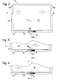
- Fig. 2 a plan view of a first embodiment of a refrigerated goods according to the invention
- Fig. 3 a partial plan view of a second embodiment of a refrigerated goods carrier
- Fig. 4 a partial plan view of a third embodiment of a refrigerated goods carrier
- Fig. 5 a section along the line VV Fig. 4 ;
- Fig. 6 a partial plan view of a fourth embodiment of a refrigerated goods carrier.
- Fig. 7 a section through the refrigerated goods of the Fig. 6 along the line VII-VII.
- Fig. 1 shows a perspective view of a refrigerator according to the invention with the door open 7.
- the refrigerator shown is a refrigerator-freezer combination with overhead cooling compartment 1 and bottom freezer 2.
- the invention will only in the following with regard to the refrigerated compartment 1 described.
- the cooling compartment 1 is subdivided into a plurality of sub-compartments or regions 5, 5 'by refrigerated goods carriers 4 suspended on the side walls 3 of the housing.
- a non-waste temperature gradient exists from a coldest location on the back wall 6 to a warmest location near the door 7.
- the lower lying regions 5 are generally colder than the higher, ie the global temperature difference between the warmest and the coldest point of the entire refrigerating compartment 1 is greater than the respective temperature differences in the individual regions 5.
- Each region 5 is associated with a respective liquid crystal temperature display 9, which is respectively arranged at the front edge of a frame of that shelf 4, which closes the relevant region 5 downwards.
- the temperature indicator 9 is thus closely adjacent to the underlying region, the temperature to which it is exposed is representative of the region above the shelf 4 since with the door closed cold air from the region in question passes over the front edge of the shelf flowing down.
- Fig. 2 shows a plan view of a shelf 4 as a first embodiment of a refrigerated goods according to the invention.
- the shelf is essentially constructed of a plate 10 made of safety glass, around the circumference around a frame 11 made of plastic molded in one piece. Of the lateral flanks of the frame 11 are in a conventional manner in each case a web 12 and a pin 13 from which serve to support the shelf in grooves on the side walls 3 of the refrigerated compartment pulled out.
- a door-facing front edge 14 of the frame 11 is chamfered like a desk, wherein on the inclined surface 15 of the front edge 14, a liquid crystal temperature display 9 is mounted.
- the display 9 is divided in this embodiment by webs 16 in a plurality of fields 17, each having between films included, a liquid crystal composition having a different color jump temperature.
- a liquid crystal composition having a different color jump temperature.
- temperature-sensitive liquid crystal compositions appear green at their transition temperature, reddish and above blue.
- a user can grasp the temperature of a region by the location of the green field 17 in the layout of the display 9, or by the number of reddish or blue fields at a glance, and the suitability of a region to store a particular type of chilled goods, such as vegetables To quickly recognize dairy or meat products.
- Fig. 3 shows a plan view of a second embodiment of a shelf 4, wherein the temperature display 9 has a continuous display zone whose liquid crystal composition varies from left to right, so that depending on the temperature to which the display is exposed, a boundary 19 between blue and Reddish area continuously with the temperature over the display zone away.
- the display zone is not divided into individual fields, a user can not easily deduce the temperature or suitability of a region 5 for a particular type of refrigerated goods from the number of fields in a particular color; instead, the frame 11, in addition to the temperature indicator 9, is provided with a series of reference marks 20 so that a user can deduce from the position of the boundary 19 with respect to reference marks 20 the suitability of the region of interest for a particular refrigeration device.
- the temperature indicator 9 also, as in Fig. 4 shown, may be provided with a temperature scale, for example in the form of zigzag windows 21 in an opaque cover layer, through which the liquid crystal material is visible, and which allow a user to read quantitatively the temperature of the region 5 concerned.
- Fig. 5 schematically shows a section through the front edge 14 of the frame 11 and the framed by this glass plate 10 along the line VV Fig. 4 , it being understood that a corresponding section in the embodiments of Figs. 2 and 3 could have the same shape.
- the molded onto the glass plate 10 leading edge 14 surrounds this material fit.
- the temperature indicator 9 is embedded in a recess 22 on the obliquely upward surface 15 of the front edge 14. It is on the inside of a rigid disc 23, for example made of transparent plastic, attached, which is bordered by molding with the material of the frame 11 along its edges in the material and thus keeps the display 9 safe and secure.
- the Figs. 6 and 7 show a fourth embodiment of a shelf 4 in a partial plan view and in section along the line VIII-VII Fig. 6 ,
- the shelf has a glass plate 10, which is not encapsulated in the present case with a frame, but at the front and (not shown) the rear edge of an extruded profile is attached as a frame element.
- the profile forming the front edge 14 has on its rear side facing the glass plate 10 a groove 24, into which the glass plate 10 can be inserted, wherein an elastic rubber or foam strip 25, which is fastened to a groove 24 bounding the lower leg 26 of the front edge 14 is elastically compressed so that it presses the top of the glass plate 10 flat against the opposite upper leg 27.
- the large-area contact allows a good heat transfer between the glass plate 10 and the front edge 14, so that the glass plate 10 can still serve as a thermal buffer for the liquid crystal temperature display 9, which is glued to the inclined surface 15 of the front edge 14.
- the temperature indicator 9 is the same in this fourth embodiment as in the third embodiment, since it is relatively complicated in an extruded profile to form features such as the webs 12 or the reference marks 20, which facilitate the reading of the display 9.
Landscapes
- Engineering & Computer Science (AREA)
- Chemical & Material Sciences (AREA)
- Combustion & Propulsion (AREA)
- Physics & Mathematics (AREA)
- Mechanical Engineering (AREA)
- Thermal Sciences (AREA)
- General Engineering & Computer Science (AREA)
- Cold Air Circulating Systems And Constructional Details In Refrigerators (AREA)
- Transition And Organic Metals Composition Catalysts For Addition Polymerization (AREA)
- Freezers Or Refrigerated Showcases (AREA)
Description
- Die vorliegende Erfindung betrifft ein Kältegerät und insbesondere einen Kühlgutträger für ein solches Kältegerät, gemäß Oberbegriff von Anspruch 1 bzw. 10.
- Die Temperaturverteilung im Innenraum eines Kältegeräts ist nicht homogen, was es insbesondere bei Kühlgeräten, mit einer Innentemperatur oberhalb des Gefrierpunkts, erlaubt, unterschiedlich temperierte Bereiche des Innenraums für verschiedene Arten von Kühlgut zu nutzen, die unterschiedliche Ansprüche an die Lagertemperatur stellen. Eine gezielte Nutzung der Temperaturunterschiede im Innenraum für diesen Zweck setzt allerdings voraus, dass ein Benutzer die in den verschiedenen Fächern des Innenraums herrschenden Temperaturen zumindest qualitativ kennt. Zu diesem Zweck ist in
DE 102 05 589 A1 eine Innenraumgestaltung für ein Kältegerät vorgeschlagen worden, bei der eine Mehrzahl von Flüssigkristalltemperaturanzeigen auf die verschiedenen Fächer des Innenraums eines Kühlgeräts verteilt sind, um es einem Benutzer zu ermöglichen, die Eignung jedes einzelnen Fachs zur Lagerung unterschiedlicher Gruppen von Kühlgütern optimal auszunutzen. - Diese Temperaturanzeigen können in einem Fach an verschiedenen Orten platziert sein, wobei es von einer günstigen Auswahl des Ortes abhängt, ob die von der Anzeige erfasste Temperatur für das Fach des Innenraums, wo sie angebracht ist, repräsentativ ist. Unter dem Gesichtspunkt einer repräsentativen Temperaturerfassung wäre es an sich wünschenswert, eine Temperaturanzeige in einem Fach zentral zwischen der Wärmesenke, meist der den Verdampfer tragenden Rückwand des Innenraums, und der Hauptwärmequelle, d.h. der Türdichtung, anzubringen. Dazu müsste man allerdings die Temperaturanzeige an einer Seitenwand des Innenbehälters anbringen, und eine solche Anzeige wäre für einen Benutzer schlecht ablesbar. Unter dem Gesichtspunkt der Ablesbarkeit ist eine Anbringung an der Vorderkante eines Kühlgutträgers, der Tür des Kältegeräts zugewandt, vorzuziehen. Eine solche Anzeige ist allerdings starken Störeinflüssen durch warme Luft ausgesetzt, die in den Innenraum eindringt, wenn ein Benutzer die Tür öffnet, so dass die von einer solchen Anzeige erfasste und angezeigte Temperatur eventuell bereits nach kurzer Öffnungszeit der Tür für den stationären Zustand des Kühlgeräts nicht mehr repräsentativ ist.
- Um dieses Problem zu vermeiden, wurde in
DE 102 05 585 A1 vorgeschlagen, die wärmeempfindlichen Flüssigkristalle einer solchen Flüssigkristalltemperaturanzeige mit einem in einem Gehäuse der Anzeige untergebrachten Wärmepuffer in Kontakt zu halten, um so der Anzeige eine gewünschte Trägheit zu verleihen. - Aufgabe der vorliegenden Erfindung ist, einen Kühlgutträger bzw. ein Kältegerät mit einem solchen Kühlgutträger anzugeben, die die Vorteile der oben beschriebenen bekannten Innenraumgestaltung mit einfacheren und preiswerteren Mitteln erreichen.
- Die Aufgabe wird gelöst durch einen Kühlgutträger mit den Merkmalen des Anspruchs 1 bzw. ein Kältegerät mit den Merkmalen des Anspruchs 10.
- Indem erfindungsgemäß ein tragendes Element des Kühlgutträgers - das durch seine Funktion bedingt im Allgemeinen über eine nicht zu vernachlässigende Masse und damit Wärmekapazität verfügt - als Wärmepuffer für die Flüssigkristalltemperaturanzeige genutzt wird, wird ein eigener Wärmepuffer der Temperahzranzeige überflüssig, so dass Platz und Kosten gespart werden können.
- Vorzugsweise ist der Wärmepuffer durch einen an eine Platte des Kühlgutträgers angeformten Rahmen gebildet. An diesem Rahmen kann die Temperataranzeige unmittelbar an einer im montierten Zustand des Kühlgutträgers der Tür des Kältegeräts zugewandten Seite angeordnet sein, so dass sie für einen Benutzer, der die Tür geöffnet hat, bequem ablesbar ist.
- Im Interesse einer guten Ablesbarkeit ist auch eine Anbringung der Flüssigkristalltemperaturanzeige an einer schräg zur Platte orientierten - im montierten Zustand schräg nach oben weisenden - Außenseite des Rahmens bevorzugt.
- Einer ersten Ausgestaltung zufolge ist ein die Flüssigkristalltemperaturanzeige tragender Teil des Rahmens durch ein Extruderprofil gebildet, das aus Kunststoff oder auch aus Metall gebildet sein kann.
- Die Flüssigkristalltemperaturanzeige kann auch an einem einteilig um die Platte des Kühlgutträgers angespritzten Rahmen angeordnet sein.
- Um das Ablesen zu erleichtern, ist die Flüssigkristalltemperaturanzeige vorzugsweise in einer Mehrzahl von diskreten Elementen gegliedert, die jeweils unterschiedliche Farbwechseltemperaturen haben. Alternativ kann eine Anzeigezone der Flüssigkristalltemperaturanzeige vorgesehen werden, in der eine Übergangszone zwischen einer Niedrigtemperaturfarbe und einer Hochtemperaturfarbe temperaturabhängig kontinuierlich beweglich ist, so dass ein Benutzer die Temperatur aus dem Ort der Übergangszone abschätzen kann. Um die Abschätzung zu quantifizieren, kann an dem tragenden Element benachbart zu der Anzeigezone eine Skala ausgebildet sein.
- Weitere Merkmale und Vorteile der Erfindung ergeben sich aus der nachfolgenden Beschreibung von Ausführungsbeispielen mit Bezug auf die beigefügten Figuren. Es zeigen:
-
Fig. 1 eine perspektivische Ansicht eines erfindungsgemäßen Kältegeräts bei geöffneter Tür; -
Fig. 2 eine Draufsicht auf eine erste Ausgestaltung eines Kühlgutträgers gemäß der Erfindung; -
Fig. 3 eine Teildraufsicht auf eine zweite Ausgestaltung eines Kühlgutträgers; -
Fig. 4 eine Teildraufsicht auf eine dritte Ausgestaltung eines Kühlgutträgers; -
Fig. 5 einen Schnitt entlang der Linie V-V ausFig. 4 ; -
Fig. 6 eine Teildraufsicht auf eine vierte Ausgestaltung eines Kühlgutträgers; und -
Fig. 7 einen Schnitt durch den Kühlgutträger derFig. 6 entlang der Linie VII-VII. -
Fig. 1 zeigt eine perspektivische Ansicht eines erfindungsgemäßen Kältegeräts bei geöffneter Tür 7. Bei dem dargestellten Kältegerät handelt es sich um eine Kühl-Gefrierkombination mit oben liegendem Kühlfach 1 und unten liegendem Gefrierfach 2. Obwohl grundsätzlich auch auf das Gefrierfach 2 anwendbar, wird die Erfindung im Folgenden nur im Hinblick auf das Kühlfach 1 beschrieben. - Das Kühlfach 1 ist durch an den Seitenwänden 3 des Gehäuses aufgehängte Kühlgutträger 4 in eine Mehrzahl von Teilfächern oder Regionen 5, 5' unterteilt. Die zwei zu unterst gelegenen Regionen 5' sind jeweils durch einen Auszugkasten 18 begrenzt, die darüber liegenden Regionen 5 sind zur Tür 7 hin offen. Sie sind durch eine in der Figur nicht sichtbaren, hinter der Rückwand 6 des Kühlfachs 1 in Höhe der Region 5 angeordneten Verdampfer gekühlt. In jeder dieser Regionen 5 existiert ein nichtverschwendender Temperaturgradient von einer kältesten Stelle an der Rückwand 6 zu einer wärmsten Stelle in der Nähe der Tür 7. Da die kalte Luft im Kühlfach 1 dazu neigt, abzusinken, sind die tiefer liegenden Regionen 5 im Allgemeinen kälter als die höheren, d.h. die globale Temperaturdifferenz zwischen dem wärmsten und dem kältesten Punkt des gesamten Kühlfachs 1 ist größer als die jeweils in den einzelnen Regionen 5 bestehenden Temperaturdifferenzen.
- Eine Gruppe von vergleichsweise warmen Regionen 5" ist durch an der Innenseite der Tür 7 montierte kastenförmige Türabsteller 8 als Kühlgutträger gebildet.
- Jeder Region 5 ist jeweils eine Flüssigkristalltemperaturanzeige 9 zugeordnet, die jeweils an der Vorderkante eines Rahmens desjenigen Fachbodens 4 angeordnet ist, der die betreffende Region 5 nach unten hin abschließt. Die Temperaturanzeige 9 ist somit zwar zur darunter liegenden Region eng benachbart, die Temperatur, der sie ausgesetzt ist, ist jedoch repräsentativ für die über den Fachboden 4 liegende Region, da bei geschlossener Tür kalte Luft aus der betreffenden Region über die Vorderkante des Fachbodens hinweg nach unten fließt.
-
Fig. 2 zeigt eine Draufsicht auf einen Fachboden 4 als erstes Ausführungsbeispiel für einen Kühlgutträger gemäß der Erfindung. Der Fachboden ist im Wesentlichen aufgebaut aus einer Platte 10 aus Sicherheitsglas, um deren Umfang herum ein Rahmen 11 aus Kunststoff einteilig angespritzt ist. Von den seitlichen Flanken des Rahmens 11 stehen in an sich bekannter Weise jeweils ein Steg 12 und ein Zapfen 13 ab, die dazu dienen, den Fachboden in Nuten an den Seitenwänden 3 des Kühlfachs herausziehbar abzustützen. Eine der Tür zugewandte Vorderkante 14 des Rahmens 11 ist pultähnlich abgeschrägt, wobei an der schrägen Oberfläche 15 der Vorderkante 14 eine Flüssigkristalltemperaturanzeige 9 angebracht ist. Die Anzeige 9 ist bei dieser Ausgestaltung durch Stege 16 in eine Vielzahl von Feldern 17 unterteilt, die jeweils, zwischen Folien eingeschlossen, eine Flüssigkristallzusammensetzung mit einer anderen Farbsprungtemperatur aufweisen. Üblicherweise erscheinen temperaturempfindliche Flüssigkristallzusammensetzungen bei ihrer Sprungtemperatur grün, darunter rötlich und darüber blau. Ein Benutzer kann die Temperatur einer Region anhand der Lage des grünen Feldes 17 in der Anordnung der Anzeige 9 oder anhand der Zahl von rötlichen oder blauen Feldern mit einem Blick erfassen und daran die Eignung einer Region für die Aufbewahrung eines bestimmten Typs von Kühlgut wie etwa Gemüse, Milchprodukte oder Fleischwaren schnell erkennen. -
Fig. 3 zeigt eine Draufsicht auf eine zweite Ausgestaltung eines Fachbodens 4, bei der die Temperaturanzeige 9 eine kontinuierliche Anzeigezone aufweist, deren Flüssigkristallzusammensetzung von links nach rechts variiert, so dass sich in Abhängigkeit von der Temperatur, der die Anzeige ausgesetzt ist, eine Grenze 19 zwischen blauem und rötlichem Bereich kontinuierlich mit der Temperatur über die Anzeigezone hinweg verschiebt. Da bei dieser Ausgestaltung die Anzeigezone nicht in einzelne Felder unterteilt ist, kann ein Benutzer die Temperatur bzw. die Eignung einer Region 5 für einen bestimmten Typ von Kühlgut nicht ohne Weiteres aus der Zahl der Felder in einer bestimmten Farbe folgern; statt dessen ist der Rahmen 11 neben der Temperaturanzeige 9 mit einer Reihe von Referenzmarken 20 versehen, so dass ein Benutzer aus der Lage der Grenze 19 in Bezug auf Referenzmarken 20 auf die Eignung der betreffenden Region für ein bestimmtes Kältegerät schließen kann. - Selbstverständlich kann die Temperaturanzeige 9 auch, wie in
Fig. 4 gezeigt, mit einer Temperaturskala versehen sein, beispielsweise in Form von zifferförmigen Fenstern 21 in einer undurchsichtigen Deckschicht, durch die hindurch das Flüssigkristallmaterial sichtbar sind, und die es einem Benutzer erlauben, die Temperatur der betreffenden Region 5 quantitativ abzulesen. -
Fig. 5 zeigt schematisch einen Schnitt durch die Vorderkante 14 des Rahmens 11 und die von diesem eingefasste Glasplatte 10 entlang der Linie V-V ausFig. 4 , wobei sich versteht, das ein entsprechender Schnitt bei den Ausgestaltungen derFigs. 2 und 3 die gleiche Form haben könnte. Die an die Glasplatte 10 angespritzte Vorderkante 14 umschließt diese materialschlüssig. Die Temperaturanzeige 9 ist in einer Vertiefung 22 an der schräg nach oben gerichteten Oberfläche 15 der Vorderkante 14 eingelassen. Sie ist an der Innenseite einer starren Scheibe 23, z.B. aus transparentem Kunststoff, angebracht, die durch Umspritzen mit dem Material des Rahmens 11 entlang ihrer Ränder in das Material eingefasst ist und so die Anzeige 9 sicher und geschützt hält. - Die
Figs. 6 und 7 zeigen eine vierte Ausgestaltung eines Fachbodens 4 in einer partiellen Draufsicht bzw. im Schnitt entlang der Linie VIII-VII ausFig. 6 . Wie im Falle derFig. 2 weist der Fachboden eine Glasplatte 10 auf, die jedoch im vorliegenden Fall nicht mit einem Rahmen umspritzt ist, sondern an deren vordere und (nicht gezeigte) hintere Kante jeweils ein extrudiertes Profil als ein Rahmenelement aufgesteckt ist. Das die Vorderkante 14 bildende Profil hat an seiner der Glasplatte 10 zugewandten Rückseite eine Nut 24, in die die Glasplatte 10 einschiebbar ist, wobei ein elastischer Gummi- oder Schaumstoffstreifen 25, der an einem die Nut 24 begrenzenden unteren Schenkel 26 der Vorderkante 14 befestigt ist, elastisch zusammengedrückt ist, so dass er die Oberseite der Glasplatte 10 flächig gegen den gegenüberliegenden oberen Schenkel 27 drückt. Der großflächige Kontakt erlaubt einen guten Wärmeübergang zwischen der Glasplatte 10 und der Vorderkante 14, so dass auch die Glasplatte 10 noch als Wärmepuffer für die Flüssigkristalltemperaturanzeige 9 dienen kann, die auf die schräge Oberfläche 15 der Vorderkante 14 aufgeklebt ist. - Die Temperaturanzeige 9 ist bei diesem vierten Ausführungsbeispiel dieselbe wie beim dritten Ausführungsbeispiel, da es bei einem extrudierten Profil vergleichsweise aufwändig ist, Merkmale wie die Stege 12 oder die Referenzmarken 20 auszubilden, die das Ablesen der Anzeige 9 erleichtern.
Claims (10)
- Kühlgutträger (4) für ein Kältegerät mit einer Flüssigkristalltemperaturanzeige (9), die eine Flüssigkristallzusammensetzung mit temperaturabhängig veränderlicher Farbe aufweist, dadurch gekennzeichnet, dass ein tragendes Element (11, 14) des Kühlgutträgers (4) als ein Wärmepuffer fungiert, an dem die Flüssigkristalltemperaturanzeige (9) flächig befestigt ist.
- Kühlgutträger nach Anspruch 1, dadurch gekennzeichnet, dass der Wärmepuffer durch einen an eine Platte (10) des Kühlgutträgers montierten Rahmen (11) gebildet ist.
- Kühlgutträger nach Anspruch 2, dadurch gekennzeichnet, dass die Flüssigkristalltemperaturanzeige an einer schräg zur Platte (10) orientierten Außenseite (15) des Rahmens (11) angebracht ist.
- Kühlgutträger nach Anspruch 2 oder 3, dadurch gekennzeichnet, dass ein die Flüssigkristalltemperaturanzeige tragender Teil (14) des Rahmens (11) ein Extruderprofil ist.
- Kühlgutträger nach Anspruch 2 oder 3, dadurch gekennzeichnet, dass der Rahmen (11) einteilig an die Platte angespritzt ist.
- Kühlgutträger nach einem der Ansprüche 1, 2, 3 und 5, dadurch gekennzeichnet, dass die Flüssigkristalltemperaturanzeige (9) mit dem tragenden Element (11) hinterspritzt ist.
- Kühlgutträger nach einem der vorhergehenden Ansprüche, dadurch gekennzeichnet, dass die Flüssigkristalltemperaturanzeige (9) in eine Mehrzahl von diskreten Elementen (17) mit unterschiedlichen Farbwechseltemperaturen gegliedert ist.
- Kühlgutträger nach einem der Ansprüche 1 bis 6, dadurch gekennzeichnet, dass die Flüssigkristalltemperaturanzeige (9) eine Anzeigezone umfasst, in der eine Übergangszone (19) zwischen einer Niedrigtemperaturfarbe und einer Hochtemperaturfarbe temperaturabhängig kontinuierlich beweglich ist.
- Kühlgutträger nach Anspruch 8, dadurch gekennzeichnet, dass an dem tragenden Element Referenzmarken (20) benachbart zu der Anzeigezone ausgebildet ist.
- Kältegerät mit einem von einem wärmeisolierenden Gehäuse umschlossenen Innenraum, dadurch gekennzeichnet, dass in dem Innenraum wenigstens ein Kühlgutträger (4) nach einem der vorhergehenden Ansprüche angebracht ist.
Applications Claiming Priority (2)
| Application Number | Priority Date | Filing Date | Title |
|---|---|---|---|
| DE20319460U DE20319460U1 (de) | 2003-12-15 | 2003-12-15 | Kältegerät und Kühlgutträger dafür |
| PCT/EP2004/053319 WO2005057108A1 (de) | 2003-12-15 | 2004-12-07 | Kältegerät und kühlgutträger dafür |
Publications (2)
| Publication Number | Publication Date |
|---|---|
| EP1702189A1 EP1702189A1 (de) | 2006-09-20 |
| EP1702189B1 true EP1702189B1 (de) | 2011-02-23 |
Family
ID=31970182
Family Applications (1)
| Application Number | Title | Priority Date | Filing Date |
|---|---|---|---|
| EP04804713A Expired - Lifetime EP1702189B1 (de) | 2003-12-15 | 2004-12-07 | Kältegerät und kühlgutträger dafür |
Country Status (8)
| Country | Link |
|---|---|
| US (1) | US20090033188A1 (de) |
| EP (1) | EP1702189B1 (de) |
| CN (1) | CN100412484C (de) |
| AT (1) | ATE499576T1 (de) |
| DE (2) | DE20319460U1 (de) |
| ES (1) | ES2359314T3 (de) |
| RU (1) | RU2362952C2 (de) |
| WO (1) | WO2005057108A1 (de) |
Families Citing this family (9)
| Publication number | Priority date | Publication date | Assignee | Title |
|---|---|---|---|---|
| DE20219911U1 (de) * | 2002-12-23 | 2003-03-13 | BSH Bosch und Siemens Hausgeräte GmbH, 81669 München | Temperaturanzeigeelement für ein Kältegerät |
| DE102012221499A1 (de) * | 2012-11-23 | 2014-05-28 | BSH Bosch und Siemens Hausgeräte GmbH | Haushaltskältegerät mit einem Anzeigemittel für einen Behälterdeckel |
| GB2523576A (en) * | 2014-02-28 | 2015-09-02 | Lcr Hallcrest Ltd | Thermometer |
| DE102014218274A1 (de) * | 2014-09-12 | 2016-03-17 | BSH Hausgeräte GmbH | Haushaltskältegerät mit einem mit integrierter Anzeigeeinheit ausgebildetem Bedienelement zum Betätigen eines Deckels eines Frischhaltebehälters |
| DE102017216189A1 (de) * | 2017-09-13 | 2019-03-14 | BSH Hausgeräte GmbH | Haushaltskältegerät mit spezifischer frontseitiger Absenkung eines Fachbodens |
| US10823490B2 (en) | 2017-10-12 | 2020-11-03 | Whirlpool Corporation | Shelf assembly for appliance |
| USD937909S1 (en) * | 2020-03-30 | 2021-12-07 | Ningbo Aquart Electrical Appliance Co., Ltd. | Ice maker |
| USD966352S1 (en) * | 2020-04-17 | 2022-10-11 | Samsung Electronics Co., Ltd. | Refrigerator |
| JPWO2025009211A1 (de) * | 2023-07-04 | 2025-01-09 |
Family Cites Families (13)
| Publication number | Priority date | Publication date | Assignee | Title |
|---|---|---|---|---|
| US5282683A (en) * | 1992-12-04 | 1994-02-01 | Liquid Crystal Sciences, Inc. | Fluid-temperature testing assembly |
| US5738442A (en) * | 1995-08-15 | 1998-04-14 | Paron; Todd C. | Wine thermometer |
| US6105233A (en) * | 1997-10-29 | 2000-08-22 | Neal; Albert D. | Shelf for a refrigerator and method of making |
| WO2001046661A1 (en) * | 1999-12-21 | 2001-06-28 | Multibrás S.A. Eletrodomésticos | A device for indicating the temperature condition in refrigeration appliances |
| KR100432713B1 (ko) * | 1999-12-30 | 2004-05-24 | 주식회사 엘지이아이 | 냉장고용 유리선반 |
| US20020002940A1 (en) * | 2000-04-25 | 2002-01-10 | Loy Randall A. | Thermometer and associated methods |
| RU17078U1 (ru) * | 2000-08-18 | 2001-03-10 | Закрытое акционерное общество "Волга-Техникс" | Полка для холодильника |
| US6544614B1 (en) * | 2000-09-21 | 2003-04-08 | Sonoco Development, Inc. | Packaging with incorporated temperature sensitive label |
| ITMI20011798A1 (it) * | 2001-08-14 | 2003-02-14 | Whirlpool Co | Elemento rimovibile per supportare alimenti in un frigorifero con mezzi atti ad impostare la temperatura del vano in cui e' posto, e frigori |
| US6585411B2 (en) * | 2001-11-02 | 2003-07-01 | Illinois Tool Works Inc. | Aerosol dispenser temperature indicator |
| US7260438B2 (en) * | 2001-11-20 | 2007-08-21 | Touchsensor Technologies, Llc | Intelligent shelving system |
| DE10205589A1 (de) * | 2002-02-11 | 2003-08-21 | Bsh Bosch Siemens Hausgeraete | Kältegerät mit Temperaturbereichskennzeichnung |
| ITMI20021179A1 (it) * | 2002-05-31 | 2003-12-01 | Whirlpool Co | Elemento di supporto per alimenti atto ad essere introdotto amovibilmente in un vano frigorifero avente zone di temperatura differenziate |
-
2003
- 2003-12-15 DE DE20319460U patent/DE20319460U1/de not_active Expired - Lifetime
-
2004
- 2004-12-07 AT AT04804713T patent/ATE499576T1/de active
- 2004-12-07 RU RU2006119147/12A patent/RU2362952C2/ru not_active IP Right Cessation
- 2004-12-07 ES ES04804713T patent/ES2359314T3/es not_active Expired - Lifetime
- 2004-12-07 DE DE502004012236T patent/DE502004012236D1/de not_active Expired - Lifetime
- 2004-12-07 WO PCT/EP2004/053319 patent/WO2005057108A1/de not_active Ceased
- 2004-12-07 US US10/582,923 patent/US20090033188A1/en not_active Abandoned
- 2004-12-07 CN CNB2004800373321A patent/CN100412484C/zh not_active Expired - Fee Related
- 2004-12-07 EP EP04804713A patent/EP1702189B1/de not_active Expired - Lifetime
Also Published As
| Publication number | Publication date |
|---|---|
| RU2362952C2 (ru) | 2009-07-27 |
| US20090033188A1 (en) | 2009-02-05 |
| WO2005057108A1 (de) | 2005-06-23 |
| CN100412484C (zh) | 2008-08-20 |
| ATE499576T1 (de) | 2011-03-15 |
| DE20319460U1 (de) | 2004-02-26 |
| EP1702189A1 (de) | 2006-09-20 |
| CN1894551A (zh) | 2007-01-10 |
| ES2359314T3 (es) | 2011-05-20 |
| RU2006119147A (ru) | 2008-01-27 |
| DE502004012236D1 (de) | 2011-04-07 |
Similar Documents
| Publication | Publication Date | Title |
|---|---|---|
| EP0037545A2 (de) | Tragbarer Isolierbehälter, insbesondere Kühltasche oder Kühlbox | |
| DE1932694A1 (de) | Regeleinrichtung fuer Kuehlanlagen | |
| DE69406208T2 (de) | Kühlmöbel | |
| EP1476705A1 (de) | Kältegerät mit temperaturbereichskennzeichnung | |
| EP2932173A1 (de) | Kältegerät mit einem türabsteller | |
| EP1702189A1 (de) | Kältegerät und kühlgutträger dafür | |
| DE202007003428U1 (de) | Kältegerät | |
| DE69829639T2 (de) | Scheinlastbehälter zur Temperaturregelung für isoliertes Kühlmöbel | |
| DE102010031696B4 (de) | Kühl-und/oder Gefriergerät | |
| EP0089556A1 (de) | Kühlregal | |
| WO2011124427A1 (de) | Fachboden für ein kältegerät | |
| EP3667209B1 (de) | Haushaltskältegerät | |
| DE102011006672A1 (de) | Temperaturanzeige für ein Kältegerät | |
| DE4411411A1 (de) | Kaltluftsammeleinrichtung für ein Kühlgerät | |
| DE102011115146A1 (de) | Kühl- und/oder Gefriergerät | |
| DE202007006160U1 (de) | Gekühltes Ausstellungsmöbel zur Beladung von der Rückseite aus | |
| WO2017137031A1 (de) | Kühlmöbel | |
| DE4432439A1 (de) | Kühlschrank mit Null-Grad-Fach | |
| DE4301148C2 (de) | Tiefkühlinsel | |
| DE69901180T2 (de) | Temperaturüberwachungsgerät für gefrorene produkte | |
| DE102008063391A1 (de) | Kältegerät mit Fachboden | |
| DE29919584U1 (de) | Transparente Kühlboxabdeckung | |
| DE10013837B4 (de) | Zumindest teilweise gekühltes Warenpräsentationsmöbel mit wenigstens einer Abdeckung | |
| DE20221969U1 (de) | Vorrichtung zur Temperaturüberwachung in einem Kältegerät | |
| DE3804863C2 (de) |
Legal Events
| Date | Code | Title | Description |
|---|---|---|---|
| PUAI | Public reference made under article 153(3) epc to a published international application that has entered the european phase |
Free format text: ORIGINAL CODE: 0009012 |
|
| 17P | Request for examination filed |
Effective date: 20060717 |
|
| AK | Designated contracting states |
Kind code of ref document: A1 Designated state(s): AT BE BG CH CY CZ DE DK EE ES FI FR GB GR HU IE IS IT LI LT LU MC NL PL PT RO SE SI SK TR |
|
| DAX | Request for extension of the european patent (deleted) | ||
| 17Q | First examination report despatched |
Effective date: 20090929 |
|
| GRAP | Despatch of communication of intention to grant a patent |
Free format text: ORIGINAL CODE: EPIDOSNIGR1 |
|
| GRAS | Grant fee paid |
Free format text: ORIGINAL CODE: EPIDOSNIGR3 |
|
| GRAA | (expected) grant |
Free format text: ORIGINAL CODE: 0009210 |
|
| AK | Designated contracting states |
Kind code of ref document: B1 Designated state(s): AT BE BG CH CY CZ DE DK EE ES FI FR GB GR HU IE IS IT LI LT LU MC NL PL PT RO SE SI SK TR |
|
| REG | Reference to a national code |
Ref country code: GB Ref legal event code: FG4D Free format text: NOT ENGLISH |
|
| REG | Reference to a national code |
Ref country code: CH Ref legal event code: EP |
|
| REG | Reference to a national code |
Ref country code: IE Ref legal event code: FG4D Free format text: LANGUAGE OF EP DOCUMENT: GERMAN |
|
| REF | Corresponds to: |
Ref document number: 502004012236 Country of ref document: DE Date of ref document: 20110407 Kind code of ref document: P |
|
| REG | Reference to a national code |
Ref country code: DE Ref legal event code: R096 Ref document number: 502004012236 Country of ref document: DE Effective date: 20110407 |
|
| REG | Reference to a national code |
Ref country code: ES Ref legal event code: FG2A Ref document number: 2359314 Country of ref document: ES Kind code of ref document: T3 Effective date: 20110520 |
|
| REG | Reference to a national code |
Ref country code: NL Ref legal event code: VDEP Effective date: 20110223 |
|
| LTIE | Lt: invalidation of european patent or patent extension |
Effective date: 20110223 |
|
| PG25 | Lapsed in a contracting state [announced via postgrant information from national office to epo] |
Ref country code: SE Free format text: LAPSE BECAUSE OF FAILURE TO SUBMIT A TRANSLATION OF THE DESCRIPTION OR TO PAY THE FEE WITHIN THE PRESCRIBED TIME-LIMIT Effective date: 20110223 Ref country code: LT Free format text: LAPSE BECAUSE OF FAILURE TO SUBMIT A TRANSLATION OF THE DESCRIPTION OR TO PAY THE FEE WITHIN THE PRESCRIBED TIME-LIMIT Effective date: 20110223 Ref country code: PT Free format text: LAPSE BECAUSE OF FAILURE TO SUBMIT A TRANSLATION OF THE DESCRIPTION OR TO PAY THE FEE WITHIN THE PRESCRIBED TIME-LIMIT Effective date: 20110623 Ref country code: GR Free format text: LAPSE BECAUSE OF FAILURE TO SUBMIT A TRANSLATION OF THE DESCRIPTION OR TO PAY THE FEE WITHIN THE PRESCRIBED TIME-LIMIT Effective date: 20110524 |
|
| PG25 | Lapsed in a contracting state [announced via postgrant information from national office to epo] |
Ref country code: FI Free format text: LAPSE BECAUSE OF FAILURE TO SUBMIT A TRANSLATION OF THE DESCRIPTION OR TO PAY THE FEE WITHIN THE PRESCRIBED TIME-LIMIT Effective date: 20110223 Ref country code: SI Free format text: LAPSE BECAUSE OF FAILURE TO SUBMIT A TRANSLATION OF THE DESCRIPTION OR TO PAY THE FEE WITHIN THE PRESCRIBED TIME-LIMIT Effective date: 20110223 Ref country code: NL Free format text: LAPSE BECAUSE OF FAILURE TO SUBMIT A TRANSLATION OF THE DESCRIPTION OR TO PAY THE FEE WITHIN THE PRESCRIBED TIME-LIMIT Effective date: 20110223 Ref country code: BG Free format text: LAPSE BECAUSE OF FAILURE TO SUBMIT A TRANSLATION OF THE DESCRIPTION OR TO PAY THE FEE WITHIN THE PRESCRIBED TIME-LIMIT Effective date: 20110523 Ref country code: CY Free format text: LAPSE BECAUSE OF FAILURE TO SUBMIT A TRANSLATION OF THE DESCRIPTION OR TO PAY THE FEE WITHIN THE PRESCRIBED TIME-LIMIT Effective date: 20110223 |
|
| REG | Reference to a national code |
Ref country code: IE Ref legal event code: FD4D |
|
| PG25 | Lapsed in a contracting state [announced via postgrant information from national office to epo] |
Ref country code: IE Free format text: LAPSE BECAUSE OF FAILURE TO SUBMIT A TRANSLATION OF THE DESCRIPTION OR TO PAY THE FEE WITHIN THE PRESCRIBED TIME-LIMIT Effective date: 20110223 Ref country code: EE Free format text: LAPSE BECAUSE OF FAILURE TO SUBMIT A TRANSLATION OF THE DESCRIPTION OR TO PAY THE FEE WITHIN THE PRESCRIBED TIME-LIMIT Effective date: 20110223 Ref country code: DK Free format text: LAPSE BECAUSE OF FAILURE TO SUBMIT A TRANSLATION OF THE DESCRIPTION OR TO PAY THE FEE WITHIN THE PRESCRIBED TIME-LIMIT Effective date: 20110223 |
|
| PG25 | Lapsed in a contracting state [announced via postgrant information from national office to epo] |
Ref country code: SK Free format text: LAPSE BECAUSE OF FAILURE TO SUBMIT A TRANSLATION OF THE DESCRIPTION OR TO PAY THE FEE WITHIN THE PRESCRIBED TIME-LIMIT Effective date: 20110223 Ref country code: RO Free format text: LAPSE BECAUSE OF FAILURE TO SUBMIT A TRANSLATION OF THE DESCRIPTION OR TO PAY THE FEE WITHIN THE PRESCRIBED TIME-LIMIT Effective date: 20110223 Ref country code: CZ Free format text: LAPSE BECAUSE OF FAILURE TO SUBMIT A TRANSLATION OF THE DESCRIPTION OR TO PAY THE FEE WITHIN THE PRESCRIBED TIME-LIMIT Effective date: 20110223 |
|
| PLBE | No opposition filed within time limit |
Free format text: ORIGINAL CODE: 0009261 |
|
| STAA | Information on the status of an ep patent application or granted ep patent |
Free format text: STATUS: NO OPPOSITION FILED WITHIN TIME LIMIT |
|
| 26N | No opposition filed |
Effective date: 20111124 |
|
| PG25 | Lapsed in a contracting state [announced via postgrant information from national office to epo] |
Ref country code: PL Free format text: LAPSE BECAUSE OF FAILURE TO SUBMIT A TRANSLATION OF THE DESCRIPTION OR TO PAY THE FEE WITHIN THE PRESCRIBED TIME-LIMIT Effective date: 20110223 |
|
| REG | Reference to a national code |
Ref country code: DE Ref legal event code: R097 Ref document number: 502004012236 Country of ref document: DE Effective date: 20111124 |
|
| BERE | Be: lapsed |
Owner name: BSH BOSCH UND SIEMENS HAUSGERATE G.M.B.H. Effective date: 20111231 |
|
| PG25 | Lapsed in a contracting state [announced via postgrant information from national office to epo] |
Ref country code: MC Free format text: LAPSE BECAUSE OF NON-PAYMENT OF DUE FEES Effective date: 20111231 |
|
| REG | Reference to a national code |
Ref country code: CH Ref legal event code: PL |
|
| PG25 | Lapsed in a contracting state [announced via postgrant information from national office to epo] |
Ref country code: BE Free format text: LAPSE BECAUSE OF NON-PAYMENT OF DUE FEES Effective date: 20111231 Ref country code: CH Free format text: LAPSE BECAUSE OF NON-PAYMENT OF DUE FEES Effective date: 20111231 Ref country code: LI Free format text: LAPSE BECAUSE OF NON-PAYMENT OF DUE FEES Effective date: 20111231 |
|
| REG | Reference to a national code |
Ref country code: AT Ref legal event code: MM01 Ref document number: 499576 Country of ref document: AT Kind code of ref document: T Effective date: 20111207 |
|
| PG25 | Lapsed in a contracting state [announced via postgrant information from national office to epo] |
Ref country code: LU Free format text: LAPSE BECAUSE OF NON-PAYMENT OF DUE FEES Effective date: 20111207 |
|
| PG25 | Lapsed in a contracting state [announced via postgrant information from national office to epo] |
Ref country code: AT Free format text: LAPSE BECAUSE OF NON-PAYMENT OF DUE FEES Effective date: 20111207 |
|
| PG25 | Lapsed in a contracting state [announced via postgrant information from national office to epo] |
Ref country code: IS Free format text: LAPSE BECAUSE OF FAILURE TO SUBMIT A TRANSLATION OF THE DESCRIPTION OR TO PAY THE FEE WITHIN THE PRESCRIBED TIME-LIMIT Effective date: 20110223 |
|
| PG25 | Lapsed in a contracting state [announced via postgrant information from national office to epo] |
Ref country code: HU Free format text: LAPSE BECAUSE OF FAILURE TO SUBMIT A TRANSLATION OF THE DESCRIPTION OR TO PAY THE FEE WITHIN THE PRESCRIBED TIME-LIMIT Effective date: 20110223 |
|
| REG | Reference to a national code |
Ref country code: DE Ref legal event code: R081 Ref document number: 502004012236 Country of ref document: DE Owner name: BSH HAUSGERAETE GMBH, DE Free format text: FORMER OWNER: BSH BOSCH UND SIEMENS HAUSGERAETE GMBH, 81739 MUENCHEN, DE Effective date: 20150407 |
|
| REG | Reference to a national code |
Ref country code: ES Ref legal event code: PC2A Owner name: BSH HAUSGERATE GMBH Effective date: 20150527 |
|
| REG | Reference to a national code |
Ref country code: FR Ref legal event code: CD Owner name: BSH HAUSGERATE GMBH Effective date: 20151022 |
|
| REG | Reference to a national code |
Ref country code: FR Ref legal event code: PLFP Year of fee payment: 12 |
|
| REG | Reference to a national code |
Ref country code: FR Ref legal event code: PLFP Year of fee payment: 13 |
|
| PGFP | Annual fee paid to national office [announced via postgrant information from national office to epo] |
Ref country code: GB Payment date: 20161222 Year of fee payment: 13 |
|
| PGFP | Annual fee paid to national office [announced via postgrant information from national office to epo] |
Ref country code: FR Payment date: 20161221 Year of fee payment: 13 Ref country code: IT Payment date: 20161220 Year of fee payment: 13 Ref country code: ES Payment date: 20161221 Year of fee payment: 13 |
|
| GBPC | Gb: european patent ceased through non-payment of renewal fee |
Effective date: 20171207 |
|
| REG | Reference to a national code |
Ref country code: FR Ref legal event code: ST Effective date: 20180831 |
|
| PG25 | Lapsed in a contracting state [announced via postgrant information from national office to epo] |
Ref country code: FR Free format text: LAPSE BECAUSE OF NON-PAYMENT OF DUE FEES Effective date: 20180102 Ref country code: IT Free format text: LAPSE BECAUSE OF NON-PAYMENT OF DUE FEES Effective date: 20171207 |
|
| PG25 | Lapsed in a contracting state [announced via postgrant information from national office to epo] |
Ref country code: GB Free format text: LAPSE BECAUSE OF NON-PAYMENT OF DUE FEES Effective date: 20171207 |
|
| REG | Reference to a national code |
Ref country code: ES Ref legal event code: FD2A Effective date: 20190702 |
|
| PG25 | Lapsed in a contracting state [announced via postgrant information from national office to epo] |
Ref country code: ES Free format text: LAPSE BECAUSE OF NON-PAYMENT OF DUE FEES Effective date: 20171208 |
|
| REG | Reference to a national code |
Ref country code: DE Ref legal event code: R084 Ref document number: 502004012236 Country of ref document: DE |
|
| PGFP | Annual fee paid to national office [announced via postgrant information from national office to epo] |
Ref country code: TR Payment date: 20231130 Year of fee payment: 20 Ref country code: DE Payment date: 20231231 Year of fee payment: 20 |
|
| REG | Reference to a national code |
Ref country code: DE Ref legal event code: R071 Ref document number: 502004012236 Country of ref document: DE |