EP1702600A1 - Krankentrage - Google Patents
Krankentrage Download PDFInfo
- Publication number
- EP1702600A1 EP1702600A1 EP06250692A EP06250692A EP1702600A1 EP 1702600 A1 EP1702600 A1 EP 1702600A1 EP 06250692 A EP06250692 A EP 06250692A EP 06250692 A EP06250692 A EP 06250692A EP 1702600 A1 EP1702600 A1 EP 1702600A1
- Authority
- EP
- European Patent Office
- Prior art keywords
- driven wheel
- arrangement
- driven
- wheels
- stretcher
- Prior art date
- Legal status (The legal status is an assumption and is not a legal conclusion. Google has not performed a legal analysis and makes no representation as to the accuracy of the status listed.)
- Granted
Links
- 238000000034 method Methods 0.000 claims description 11
- 230000000694 effects Effects 0.000 claims description 7
- 230000007423 decrease Effects 0.000 claims description 2
- 230000001419 dependent effect Effects 0.000 claims 1
- 235000004443 Ricinus communis Nutrition 0.000 abstract description 26
- 230000007704 transition Effects 0.000 description 11
- 240000000528 Ricinus communis Species 0.000 description 3
- 230000008602 contraction Effects 0.000 description 1
- 239000012530 fluid Substances 0.000 description 1
- 230000006698 induction Effects 0.000 description 1
- 238000007689 inspection Methods 0.000 description 1
Images

Classifications
-
- A—HUMAN NECESSITIES
- A61—MEDICAL OR VETERINARY SCIENCE; HYGIENE
- A61G—TRANSPORT, PERSONAL CONVEYANCES, OR ACCOMMODATION SPECIALLY ADAPTED FOR PATIENTS OR DISABLED PERSONS; OPERATING TABLES OR CHAIRS; CHAIRS FOR DENTISTRY; FUNERAL DEVICES
- A61G7/00—Beds specially adapted for nursing; Devices for lifting patients or disabled persons
- A61G7/08—Apparatus for transporting beds
-
- A—HUMAN NECESSITIES
- A61—MEDICAL OR VETERINARY SCIENCE; HYGIENE
- A61G—TRANSPORT, PERSONAL CONVEYANCES, OR ACCOMMODATION SPECIALLY ADAPTED FOR PATIENTS OR DISABLED PERSONS; OPERATING TABLES OR CHAIRS; CHAIRS FOR DENTISTRY; FUNERAL DEVICES
- A61G1/00—Stretchers
- A61G1/02—Stretchers with wheels
- A61G1/0206—Stretchers with wheels characterised by the number of supporting wheels if stretcher is extended
- A61G1/0218—3 pairs having wheels within a pair on the same position in longitudinal direction, e.g. on the same axis
-
- A—HUMAN NECESSITIES
- A61—MEDICAL OR VETERINARY SCIENCE; HYGIENE
- A61G—TRANSPORT, PERSONAL CONVEYANCES, OR ACCOMMODATION SPECIALLY ADAPTED FOR PATIENTS OR DISABLED PERSONS; OPERATING TABLES OR CHAIRS; CHAIRS FOR DENTISTRY; FUNERAL DEVICES
- A61G1/00—Stretchers
- A61G1/02—Stretchers with wheels
- A61G1/0237—Stretchers with wheels having at least one swivelling wheel, e.g. castors
-
- A—HUMAN NECESSITIES
- A61—MEDICAL OR VETERINARY SCIENCE; HYGIENE
- A61G—TRANSPORT, PERSONAL CONVEYANCES, OR ACCOMMODATION SPECIALLY ADAPTED FOR PATIENTS OR DISABLED PERSONS; OPERATING TABLES OR CHAIRS; CHAIRS FOR DENTISTRY; FUNERAL DEVICES
- A61G1/00—Stretchers
- A61G1/02—Stretchers with wheels
- A61G1/025—Stretchers with wheels having auxiliary wheels, e.g. wheels not touching the ground in extended position
- A61G1/0268—Stretchers with wheels having auxiliary wheels, e.g. wheels not touching the ground in extended position having deployable or retractable wheels
-
- A—HUMAN NECESSITIES
- A61—MEDICAL OR VETERINARY SCIENCE; HYGIENE
- A61G—TRANSPORT, PERSONAL CONVEYANCES, OR ACCOMMODATION SPECIALLY ADAPTED FOR PATIENTS OR DISABLED PERSONS; OPERATING TABLES OR CHAIRS; CHAIRS FOR DENTISTRY; FUNERAL DEVICES
- A61G1/00—Stretchers
- A61G1/02—Stretchers with wheels
- A61G1/0275—Stretchers with wheels having driven wheels, e.g. motorised
-
- A—HUMAN NECESSITIES
- A61—MEDICAL OR VETERINARY SCIENCE; HYGIENE
- A61G—TRANSPORT, PERSONAL CONVEYANCES, OR ACCOMMODATION SPECIALLY ADAPTED FOR PATIENTS OR DISABLED PERSONS; OPERATING TABLES OR CHAIRS; CHAIRS FOR DENTISTRY; FUNERAL DEVICES
- A61G1/00—Stretchers
- A61G1/02—Stretchers with wheels
- A61G1/0287—Stretchers with wheels having brakes, e.g. slowing down and/or holding
-
- A—HUMAN NECESSITIES
- A61—MEDICAL OR VETERINARY SCIENCE; HYGIENE
- A61G—TRANSPORT, PERSONAL CONVEYANCES, OR ACCOMMODATION SPECIALLY ADAPTED FOR PATIENTS OR DISABLED PERSONS; OPERATING TABLES OR CHAIRS; CHAIRS FOR DENTISTRY; FUNERAL DEVICES
- A61G7/00—Beds specially adapted for nursing; Devices for lifting patients or disabled persons
- A61G7/05—Parts, details or accessories of beds
- A61G7/0528—Steering or braking devices for castor wheels
Definitions
- the present invention relates to a stretcher and a method of operating a stretcher.
- any reference to a stretcher includes a stretcher trolley.
- Stretchers are presently manoeuvred manually by an operator who exerts the forces required to direct and move the stretcher about hospital ward, between wards, between ambulances and between ambulances and incidents.
- the operator has to exert a considerable force in order to control the stretcher. The effect can be bad for the back of the operator.
- the force is increased when manoeuvring the stretcher up steep inclines or ramps, such as an ambulance ramp or hospital ramp.
- the wheels of the stretcher are mounted on swivels, which, particularly if the ramp tilts to one side (such as may occur when the vehicle is not parked on level ground), as the operator pushes the stretcher up it can run off the stretcher.
- the stretcher can run off course when going up or down hill or on a slope.
- the stretcher can run away down hill if on a steep hill or if the operator slips and loses grip. All of these problems are accentuated when the patient on the stretcher is particularly heavy.
- a stretcher trolley arrangement includes at least three non-driven wheels and at least one driven wheel, the driven wheel being moveable relative to at least one of the non-driven wheels between a driving position in which the driven wheel is in contact with the ground and a non-driving position in which the driven wheel is spaced from the ground.
- At least one of the driven wheels or a non-driven wheel may be moveably mounted on the stretcher in order to effect the movement between the two positions.
- At least one of the non-driven wheels may be spaced on the ground.
- the driven wheel may be pivotally mounted on the stretcher about an axis offset from that wheels rotational axis to effect the movement between the driven and non-driven positions.
- the movement in at least one direction between the positions may be effected by driving means.
- the drive means may be arranged to hold the stretcher in at least one of the positions with the hold being exerted in at least one of the positions being releasable.
- the movement from at least one position to another may be effected by manual movement of a telescopic arm.
- the movement in at least one direction between the positions may be effected by driving means which may include an extendable and contractible member pivotably connected to the stretcher and a link at a location spaced from the pivotal mounting of the link to the stretcher.
- the movement from the driving position to the non-driving position may be at least initially pivotal movement about the point of contact of the driven wheel with the ground.
- the driven wheel may be larger than the non-driven wheel such as being more than twice the diameter of the non-driven wheel.
- the drive When the wheel is in the driving position the drive may be arranged to be able to act as a brake should the stretcher be going down an incline.
- the arrangement may include a battery arranged to power the drive wheel.
- a battery may be arranged to drive the movement between at least one of the positions.
- the angle of the axis of the driven wheel may be fixed with respect to the longitudinal extent of the stretcher.
- the axis of at least one non-driven wheel may be able to move about an upwardly extending axis and may be selectively lockable in at least one position of the upwardly extending axis.
- the driven wheel may be located between non-driven wheels in the direction of longitudinal extent of the stretcher.
- the non-driven wheel may be located towards one end of the stretcher in the region of a support extending up from a lower region of the trolley to a support for a body.
- the driven wheel may be pivotally connected to the support.
- the driven wheel and the non-driven wheel may be located in the region of the support with each being either side of the support in the longitudinal extent of the trolley.
- the method may comprise causing at least one non-driven wheel to be clear of the ground in the driving position.
- the method may comprise causing the non-driven wheel to be clear of the ground in the driving position at a location spaced from the longitudinal extent of the remaining wheels in contact with the ground.
- the drive means may include, although by no means be limited to, linear lead-screw actuators, hydraulic actuators, or electro-hydraulic actuators.
- the present invention includes any combination of the herein referred to features or limitations.
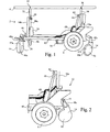
- the patient support 4 is mounted on a first support 32, which extends upwardly from the front of the main fame 10, and a second support 34, which extends upwardly from the rear of the main frame 10 so that the patient support 4 is held mainly flat or horizontal.
- the lower end of the second, rear support 34 is fixed to an upwardly extending arm 10a of the main frame 10.
- the upper end region of the second, rear support 34 is connected by a first group of co-operating parts 36 to the patient support 4.
- the lower end region of the first, front support 32 is attached to a piston of a first linear actuator 38 by a second group of co-operating parts 40.
- the upper end region of the first support 32 is connected by a third group of co-operating parts 42 to the patient support 4.
- the lower end of the actuator 38 is fixed to an upwardly extending arm 10b of the main frame 10.
- the configuration of the patient support 4, the first support 32, the second support 34, the first linear actuator 38, and the three groups of co-operating parts 36 and 42 is such that the first linear actuator may be driven to extend or contract a piston 38a of the linear actuator in order to incline or decline the angle of the patient support 4.
- the patient support 4 When inclined, the patient support 4 may, for instance, be raised up to 15° to drain fluid from the legs of a patient on the support 4 with pivot occurring about the parts 36.
- the first linear actuator 38 may be controlled by an operator controlling a two-position or multi-position switch, such as a rocker switch, which may be positioned at the rear of the trolley.
- a battery 56 mounted on the main frame 10 is able to power the actuator 38 in order to extend or contract the piston 38a using any well known method.
- the main frame 10 provides the housing for the two front castor wheels 6a and 6b.
- the castor wheels 6a and 6b are aligned substantially in the same plane and at the first trolley end region and are spaced apart laterally across the stretcher, generally being positioned on the widest portion of the main frame 10.
- the front castor wheels are able to rotate about a horizontal axis and can swivel about a vertical axis on a stub shaft 47, offset from the horizontal axis.
- the rear castor wheels 6c and 6d are able to rotate in the same way as the front castor wheels and, in addition.
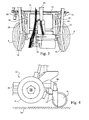
- a sub frame comprising of two side rails 50 and two cross rails 52 is pivotally mounted at points 20 on the main frame 10 at the rear end such that the sub frame 16 is able to pivot about a horizontal axis.
- a rear castor wheels 6c and 6d are located on the rearward projecting end region of the sub frame 16.
- the castor wheel sub axles 48 of the rear castor wheels pivot with the sub frame about the pivot points 20.
- the driven wheels 8 are mounted on axles 54 that project from a forward region of the sub frame, spaced from the pivot points 20 of the sub frame.
- the battery 56 powers a motor 58 mounted on the axle 54 or the sub frame 16 in order to drive the axle 54 and subsequently the wheels 8 in any well known manner.
- the motor may impart a drive via an induction force being applied to a magnet fast with the axles 54.
- a second actuator 60 controls the movement of the sub frame 16 about the pivot points 20.
- the second actuator 60 is rotatably fixed at the upper end to the upwardly extending arm 10a just forward of that arm.
- the lower end of the actuator 60 is pivotally connected to the axle 54 of the sub frame 6 such that when the piston 66 of the second actuator 60 is extended or contracted the point at which the actuator 60 is located on the sub frame 16 moves up or down through a circumferential path by rotating about the pivot points 20.
- the battery 56 powers the actuator 60 to extend or contract a piston 66 of the actuator.
- a two-position switch such as a rocker switch, which may be positioned at the rear end of the trolley and controlled by an operator, may control the extension or contraction of the actuator 60.
- the stretcher can be moved by an operator at the rear of the trolley using a lever, which initiates and varies the speed of rotation of the drive shaft from the motor and the speed of travel of the trolley.
- the lever can be moved in an opposite direction to initiate and vary the speed of reverse rotation of the axle 54.
- the motor may include a positive drive that prevents the axle 66 from being able to rotate faster than that set by the lever to prevent the runaway of the stretcher down inclines.
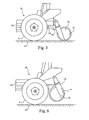
- the actuator piston 66 may contract to initiate the transition to the first position 22. Alternatively the actuator may relax such that all driven and non driven wheels contact the ground.
- a telescopic lever 31 held fast to the sub frame is extended from the sub frame 16 by any well-known means.
- the actuator piston 66 is unloaded such that the co-operating parts of the actuator 60 do not resist rotational movement of the sub frame 16.
- a downwards force exerted on the lever 31 by the hand or foot of an operator acts to rotate the sub frame 16 in to the first transition position.
- the actuator piston 66 may be re-locked in order to impart the necessary rotational movement of the sub frame 16 or the lever may be moved sideways to engage with a locking part of the main frame. Return movement and locking is a reverse of this operation.
- the pistons may comprise linear actuators whereby a nut is axially fixed but rotated to drive the piston axially with regard to the rotation of the nut.
Landscapes
- Health & Medical Sciences (AREA)
- Life Sciences & Earth Sciences (AREA)
- Animal Behavior & Ethology (AREA)
- General Health & Medical Sciences (AREA)
- Public Health (AREA)
- Veterinary Medicine (AREA)
- Nursing (AREA)
- Handcart (AREA)
- Weting (AREA)
- Invalid Beds And Related Equipment (AREA)
- Devices That Are Associated With Refrigeration Equipment (AREA)
Applications Claiming Priority (1)
| Application Number | Priority Date | Filing Date | Title |
|---|---|---|---|
| GB0505447A GB2424215A (en) | 2005-03-17 | 2005-03-17 | Power-assisted stretcher |
Publications (2)
| Publication Number | Publication Date |
|---|---|
| EP1702600A1 true EP1702600A1 (de) | 2006-09-20 |
| EP1702600B1 EP1702600B1 (de) | 2008-12-17 |
Family
ID=34509196
Family Applications (1)
| Application Number | Title | Priority Date | Filing Date |
|---|---|---|---|
| EP06250692A Expired - Lifetime EP1702600B1 (de) | 2005-03-17 | 2006-02-09 | Krankentrage |
Country Status (4)
| Country | Link |
|---|---|
| EP (1) | EP1702600B1 (de) |
| AT (1) | ATE417587T1 (de) |
| DE (1) | DE602006004233D1 (de) |
| GB (1) | GB2424215A (de) |
Cited By (1)
| Publication number | Priority date | Publication date | Assignee | Title |
|---|---|---|---|---|
| WO2011016054A3 (en) * | 2009-08-03 | 2011-03-31 | Subhav Sinha | Dynamically stabilized personal transporter |
Families Citing this family (1)
| Publication number | Priority date | Publication date | Assignee | Title |
|---|---|---|---|---|
| CN109248030A (zh) * | 2018-10-05 | 2019-01-22 | 丁君浩 | 一种医疗转运床及配套医用伸缩机构 |
Citations (2)
| Publication number | Priority date | Publication date | Assignee | Title |
|---|---|---|---|---|
| EP0769286A2 (de) | 1995-09-25 | 1997-04-23 | Naoto Fujii | Patiententransfervorrichtung |
| US20030159861A1 (en) | 2002-02-28 | 2003-08-28 | Hopper Christopher J. | Wheeled carriage having a powered auxiliary wheel, auxiliary wheel overtravel, and an auxiliary wheel drive and control system |
Family Cites Families (5)
| Publication number | Priority date | Publication date | Assignee | Title |
|---|---|---|---|---|
| US5083625A (en) * | 1990-07-02 | 1992-01-28 | Bleicher Joel N | Powdered maneuverable hospital cart |
| JP2000107230A (ja) * | 1998-10-09 | 2000-04-18 | S N Seiki:Kk | ストレッチャーの装着ユニット |
| US6772850B1 (en) * | 2000-01-21 | 2004-08-10 | Stryker Corporation | Power assisted wheeled carriage |
| EP2308437B1 (de) * | 2000-05-11 | 2014-07-09 | Hill-Rom Services, Inc. | Motorisierte Zugvorrichtung für eine Patientenliege |
| US6725956B1 (en) * | 2003-05-06 | 2004-04-27 | Stryker Corporation | Fifth wheel for bed |
-
2005
- 2005-03-17 GB GB0505447A patent/GB2424215A/en not_active Withdrawn
-
2006
- 2006-02-09 DE DE602006004233T patent/DE602006004233D1/de not_active Expired - Fee Related
- 2006-02-09 EP EP06250692A patent/EP1702600B1/de not_active Expired - Lifetime
- 2006-02-09 AT AT06250692T patent/ATE417587T1/de not_active IP Right Cessation
Patent Citations (2)
| Publication number | Priority date | Publication date | Assignee | Title |
|---|---|---|---|---|
| EP0769286A2 (de) | 1995-09-25 | 1997-04-23 | Naoto Fujii | Patiententransfervorrichtung |
| US20030159861A1 (en) | 2002-02-28 | 2003-08-28 | Hopper Christopher J. | Wheeled carriage having a powered auxiliary wheel, auxiliary wheel overtravel, and an auxiliary wheel drive and control system |
Cited By (1)
| Publication number | Priority date | Publication date | Assignee | Title |
|---|---|---|---|---|
| WO2011016054A3 (en) * | 2009-08-03 | 2011-03-31 | Subhav Sinha | Dynamically stabilized personal transporter |
Also Published As
| Publication number | Publication date |
|---|---|
| GB2424215A (en) | 2006-09-20 |
| DE602006004233D1 (de) | 2009-01-29 |
| GB0505447D0 (en) | 2005-04-20 |
| EP1702600B1 (de) | 2008-12-17 |
| ATE417587T1 (de) | 2009-01-15 |
Similar Documents
| Publication | Publication Date | Title |
|---|---|---|
| US7896118B2 (en) | Stretchers | |
| JP7796147B2 (ja) | 機敏な移動式シザーリフト装置 | |
| US11865055B2 (en) | Seat positioning system for a wheelchair | |
| US11883334B2 (en) | Deployment patient transport apparatus with controlled auxiliary wheel deployment | |
| EP4240632B1 (de) | Palettenhubwagen mit einstellbarem gabelabstand | |
| US20150374564A1 (en) | A wheeled vehicle and a method of operation thereof | |
| US7100718B2 (en) | Adjustable wheelchair | |
| EP2641810A2 (de) | Systeme und Verfahren zum Lenken von Fahrzeugen | |
| AU2016286281A1 (en) | Wheel drive mechanism for patient handling equipment | |
| US20050057010A1 (en) | Pedal control of brake and auxiliary wheel deployment via side and end articulation | |
| MXPA06004922A (es) | Dispositivo maniobrable para transportar cargas sobre una superficie. | |
| US20150014959A1 (en) | Patient transport platform | |
| JP2001502957A (ja) | 事故および緊急用搬送台車 | |
| WO2018174781A1 (en) | Transport cart | |
| EP1702600B1 (de) | Krankentrage | |
| US8534415B2 (en) | Center-pivot steering articulated vehicle with load lifting trailer | |
| US20230201055A1 (en) | Removable electronic propulsion system for a rolling object with an automatic directional blocking means | |
| US20200277745A1 (en) | Method and apparatus for safely and quickly removing snow from narrow pedestrian and vehicular paths | |
| CN211560723U (zh) | 智能越障车 | |
| CN114028087A (zh) | 一种防倾斜的轮椅 | |
| US20260090934A1 (en) | Power drive wheel mechanism for patient support apparatus | |
| AU2002333033B2 (en) | Adjustable wheelchair | |
| GB2337030A (en) | A mobile chassis for an invalid hoist | |
| GB2377422A (en) | Lifting vehicle wheels | |
| AU2002333033A1 (en) | Adjustable wheelchair |
Legal Events
| Date | Code | Title | Description |
|---|---|---|---|
| PUAI | Public reference made under article 153(3) epc to a published international application that has entered the european phase |
Free format text: ORIGINAL CODE: 0009012 |
|
| AK | Designated contracting states |
Kind code of ref document: A1 Designated state(s): AT BE BG CH CY CZ DE DK EE ES FI FR GB GR HU IE IS IT LI LT LU LV MC NL PL PT RO SE SI SK TR |
|
| AX | Request for extension of the european patent |
Extension state: AL BA HR MK YU |
|
| 17P | Request for examination filed |
Effective date: 20070102 |
|
| 17Q | First examination report despatched |
Effective date: 20070207 |
|
| AKX | Designation fees paid |
Designated state(s): AT BE BG CH CY CZ DE DK EE ES FI FR GB GR HU IE IS IT LI LT LU LV MC NL PL PT RO SE SI SK TR |
|
| GRAP | Despatch of communication of intention to grant a patent |
Free format text: ORIGINAL CODE: EPIDOSNIGR1 |
|
| GRAS | Grant fee paid |
Free format text: ORIGINAL CODE: EPIDOSNIGR3 |
|
| GRAA | (expected) grant |
Free format text: ORIGINAL CODE: 0009210 |
|
| AK | Designated contracting states |
Kind code of ref document: B1 Designated state(s): AT BE BG CH CY CZ DE DK EE ES FI FR GB GR HU IE IS IT LI LT LU LV MC NL PL PT RO SE SI SK TR |
|
| REG | Reference to a national code |
Ref country code: GB Ref legal event code: FG4D |
|
| REG | Reference to a national code |
Ref country code: CH Ref legal event code: EP |
|
| REG | Reference to a national code |
Ref country code: IE Ref legal event code: FG4D |
|
| REF | Corresponds to: |
Ref document number: 602006004233 Country of ref document: DE Date of ref document: 20090129 Kind code of ref document: P |
|
| PG25 | Lapsed in a contracting state [announced via postgrant information from national office to epo] |
Ref country code: LT Free format text: LAPSE BECAUSE OF FAILURE TO SUBMIT A TRANSLATION OF THE DESCRIPTION OR TO PAY THE FEE WITHIN THE PRESCRIBED TIME-LIMIT Effective date: 20081217 |
|
| PG25 | Lapsed in a contracting state [announced via postgrant information from national office to epo] |
Ref country code: LV Free format text: LAPSE BECAUSE OF FAILURE TO SUBMIT A TRANSLATION OF THE DESCRIPTION OR TO PAY THE FEE WITHIN THE PRESCRIBED TIME-LIMIT Effective date: 20081217 Ref country code: SI Free format text: LAPSE BECAUSE OF FAILURE TO SUBMIT A TRANSLATION OF THE DESCRIPTION OR TO PAY THE FEE WITHIN THE PRESCRIBED TIME-LIMIT Effective date: 20081217 Ref country code: PL Free format text: LAPSE BECAUSE OF FAILURE TO SUBMIT A TRANSLATION OF THE DESCRIPTION OR TO PAY THE FEE WITHIN THE PRESCRIBED TIME-LIMIT Effective date: 20081217 Ref country code: FI Free format text: LAPSE BECAUSE OF FAILURE TO SUBMIT A TRANSLATION OF THE DESCRIPTION OR TO PAY THE FEE WITHIN THE PRESCRIBED TIME-LIMIT Effective date: 20081217 |
|
| PGFP | Annual fee paid to national office [announced via postgrant information from national office to epo] |
Ref country code: DE Payment date: 20081222 Year of fee payment: 4 Ref country code: NL Payment date: 20090224 Year of fee payment: 4 |
|
| PG25 | Lapsed in a contracting state [announced via postgrant information from national office to epo] |
Ref country code: EE Free format text: LAPSE BECAUSE OF FAILURE TO SUBMIT A TRANSLATION OF THE DESCRIPTION OR TO PAY THE FEE WITHIN THE PRESCRIBED TIME-LIMIT Effective date: 20081217 Ref country code: ES Free format text: LAPSE BECAUSE OF FAILURE TO SUBMIT A TRANSLATION OF THE DESCRIPTION OR TO PAY THE FEE WITHIN THE PRESCRIBED TIME-LIMIT Effective date: 20090328 Ref country code: RO Free format text: LAPSE BECAUSE OF FAILURE TO SUBMIT A TRANSLATION OF THE DESCRIPTION OR TO PAY THE FEE WITHIN THE PRESCRIBED TIME-LIMIT Effective date: 20081217 Ref country code: BG Free format text: LAPSE BECAUSE OF FAILURE TO SUBMIT A TRANSLATION OF THE DESCRIPTION OR TO PAY THE FEE WITHIN THE PRESCRIBED TIME-LIMIT Effective date: 20090317 Ref country code: BE Free format text: LAPSE BECAUSE OF FAILURE TO SUBMIT A TRANSLATION OF THE DESCRIPTION OR TO PAY THE FEE WITHIN THE PRESCRIBED TIME-LIMIT Effective date: 20081217 |
|
| PG25 | Lapsed in a contracting state [announced via postgrant information from national office to epo] |
Ref country code: SE Free format text: LAPSE BECAUSE OF FAILURE TO SUBMIT A TRANSLATION OF THE DESCRIPTION OR TO PAY THE FEE WITHIN THE PRESCRIBED TIME-LIMIT Effective date: 20090317 Ref country code: AT Free format text: LAPSE BECAUSE OF FAILURE TO SUBMIT A TRANSLATION OF THE DESCRIPTION OR TO PAY THE FEE WITHIN THE PRESCRIBED TIME-LIMIT Effective date: 20081217 Ref country code: PT Free format text: LAPSE BECAUSE OF FAILURE TO SUBMIT A TRANSLATION OF THE DESCRIPTION OR TO PAY THE FEE WITHIN THE PRESCRIBED TIME-LIMIT Effective date: 20090518 Ref country code: CZ Free format text: LAPSE BECAUSE OF FAILURE TO SUBMIT A TRANSLATION OF THE DESCRIPTION OR TO PAY THE FEE WITHIN THE PRESCRIBED TIME-LIMIT Effective date: 20081217 Ref country code: IS Free format text: LAPSE BECAUSE OF FAILURE TO SUBMIT A TRANSLATION OF THE DESCRIPTION OR TO PAY THE FEE WITHIN THE PRESCRIBED TIME-LIMIT Effective date: 20090417 |
|
| PG25 | Lapsed in a contracting state [announced via postgrant information from national office to epo] |
Ref country code: SK Free format text: LAPSE BECAUSE OF FAILURE TO SUBMIT A TRANSLATION OF THE DESCRIPTION OR TO PAY THE FEE WITHIN THE PRESCRIBED TIME-LIMIT Effective date: 20081217 Ref country code: MC Free format text: LAPSE BECAUSE OF NON-PAYMENT OF DUE FEES Effective date: 20090228 |
|
| PLBE | No opposition filed within time limit |
Free format text: ORIGINAL CODE: 0009261 |
|
| STAA | Information on the status of an ep patent application or granted ep patent |
Free format text: STATUS: NO OPPOSITION FILED WITHIN TIME LIMIT |
|
| PG25 | Lapsed in a contracting state [announced via postgrant information from national office to epo] |
Ref country code: DK Free format text: LAPSE BECAUSE OF FAILURE TO SUBMIT A TRANSLATION OF THE DESCRIPTION OR TO PAY THE FEE WITHIN THE PRESCRIBED TIME-LIMIT Effective date: 20081217 |
|
| PGFP | Annual fee paid to national office [announced via postgrant information from national office to epo] |
Ref country code: FR Payment date: 20081223 Year of fee payment: 4 |
|
| 26N | No opposition filed |
Effective date: 20090918 |
|
| REG | Reference to a national code |
Ref country code: IE Ref legal event code: MM4A |
|
| PG25 | Lapsed in a contracting state [announced via postgrant information from national office to epo] |
Ref country code: IE Free format text: LAPSE BECAUSE OF NON-PAYMENT OF DUE FEES Effective date: 20090209 |
|
| REG | Reference to a national code |
Ref country code: NL Ref legal event code: V1 Effective date: 20100901 |
|
| REG | Reference to a national code |
Ref country code: CH Ref legal event code: PL |
|
| PG25 | Lapsed in a contracting state [announced via postgrant information from national office to epo] |
Ref country code: LI Free format text: LAPSE BECAUSE OF NON-PAYMENT OF DUE FEES Effective date: 20100228 Ref country code: GR Free format text: LAPSE BECAUSE OF FAILURE TO SUBMIT A TRANSLATION OF THE DESCRIPTION OR TO PAY THE FEE WITHIN THE PRESCRIBED TIME-LIMIT Effective date: 20090318 Ref country code: CH Free format text: LAPSE BECAUSE OF NON-PAYMENT OF DUE FEES Effective date: 20100228 |
|
| REG | Reference to a national code |
Ref country code: FR Ref legal event code: ST Effective date: 20101029 |
|
| PG25 | Lapsed in a contracting state [announced via postgrant information from national office to epo] |
Ref country code: FR Free format text: LAPSE BECAUSE OF NON-PAYMENT OF DUE FEES Effective date: 20100301 Ref country code: NL Free format text: LAPSE BECAUSE OF NON-PAYMENT OF DUE FEES Effective date: 20100901 |
|
| PG25 | Lapsed in a contracting state [announced via postgrant information from national office to epo] |
Ref country code: DE Free format text: LAPSE BECAUSE OF NON-PAYMENT OF DUE FEES Effective date: 20100901 |
|
| PG25 | Lapsed in a contracting state [announced via postgrant information from national office to epo] |
Ref country code: IT Free format text: LAPSE BECAUSE OF FAILURE TO SUBMIT A TRANSLATION OF THE DESCRIPTION OR TO PAY THE FEE WITHIN THE PRESCRIBED TIME-LIMIT Effective date: 20081217 |
|
| PG25 | Lapsed in a contracting state [announced via postgrant information from national office to epo] |
Ref country code: LU Free format text: LAPSE BECAUSE OF NON-PAYMENT OF DUE FEES Effective date: 20090209 |
|
| PG25 | Lapsed in a contracting state [announced via postgrant information from national office to epo] |
Ref country code: HU Free format text: LAPSE BECAUSE OF FAILURE TO SUBMIT A TRANSLATION OF THE DESCRIPTION OR TO PAY THE FEE WITHIN THE PRESCRIBED TIME-LIMIT Effective date: 20090618 |
|
| PG25 | Lapsed in a contracting state [announced via postgrant information from national office to epo] |
Ref country code: TR Free format text: LAPSE BECAUSE OF FAILURE TO SUBMIT A TRANSLATION OF THE DESCRIPTION OR TO PAY THE FEE WITHIN THE PRESCRIBED TIME-LIMIT Effective date: 20081217 |
|
| PG25 | Lapsed in a contracting state [announced via postgrant information from national office to epo] |
Ref country code: CY Free format text: LAPSE BECAUSE OF FAILURE TO SUBMIT A TRANSLATION OF THE DESCRIPTION OR TO PAY THE FEE WITHIN THE PRESCRIBED TIME-LIMIT Effective date: 20081217 |
|
| PGFP | Annual fee paid to national office [announced via postgrant information from national office to epo] |
Ref country code: GB Payment date: 20140225 Year of fee payment: 9 |
|
| GBPC | Gb: european patent ceased through non-payment of renewal fee |
Effective date: 20150209 |
|
| PG25 | Lapsed in a contracting state [announced via postgrant information from national office to epo] |
Ref country code: GB Free format text: LAPSE BECAUSE OF NON-PAYMENT OF DUE FEES Effective date: 20150209 |