EP1702694A1 - Werkzeugspannfutter für drehende Maschine, mit Verriegelungsmittel - Google Patents
Werkzeugspannfutter für drehende Maschine, mit Verriegelungsmittel Download PDFInfo
- Publication number
- EP1702694A1 EP1702694A1 EP06356023A EP06356023A EP1702694A1 EP 1702694 A1 EP1702694 A1 EP 1702694A1 EP 06356023 A EP06356023 A EP 06356023A EP 06356023 A EP06356023 A EP 06356023A EP 1702694 A1 EP1702694 A1 EP 1702694A1
- Authority
- EP
- European Patent Office
- Prior art keywords
- locking
- central piece
- clamping ring
- jaws
- finger
- Prior art date
- Legal status (The legal status is an assumption and is not a legal conclusion. Google has not performed a legal analysis and makes no representation as to the accuracy of the status listed.)
- Granted
Links
- 230000002093 peripheral effect Effects 0.000 claims description 16
- 238000011144 upstream manufacturing Methods 0.000 claims description 13
- 239000002184 metal Substances 0.000 claims description 3
- KWGRBVOPPLSCSI-WPRPVWTQSA-N (-)-ephedrine Chemical compound CN[C@@H](C)[C@H](O)C1=CC=CC=C1 KWGRBVOPPLSCSI-WPRPVWTQSA-N 0.000 description 4
- 238000006073 displacement reaction Methods 0.000 description 4
- 230000000903 blocking effect Effects 0.000 description 3
- 238000009527 percussion Methods 0.000 description 2
- 208000031968 Cadaver Diseases 0.000 description 1
- 230000004323 axial length Effects 0.000 description 1
- 238000005553 drilling Methods 0.000 description 1
- 230000000694 effects Effects 0.000 description 1
- 238000004049 embossing Methods 0.000 description 1
- 230000012447 hatching Effects 0.000 description 1
- 238000007373 indentation Methods 0.000 description 1
- 239000000463 material Substances 0.000 description 1
Images



Classifications
-
- B—PERFORMING OPERATIONS; TRANSPORTING
- B23—MACHINE TOOLS; METAL-WORKING NOT OTHERWISE PROVIDED FOR
- B23B—TURNING; BORING
- B23B31/00—Chucks; Expansion mandrels; Adaptations thereof for remote control
- B23B31/02—Chucks
- B23B31/10—Chucks characterised by the retaining or gripping devices or their immediate operating means
- B23B31/12—Chucks with simultaneously-acting jaws, whether or not also individually adjustable
- B23B31/1207—Chucks with simultaneously-acting jaws, whether or not also individually adjustable moving obliquely to the axis of the chuck in a plane containing this axis
- B23B31/123—Chucks with simultaneously-acting jaws, whether or not also individually adjustable moving obliquely to the axis of the chuck in a plane containing this axis with locking arrangements
-
- B—PERFORMING OPERATIONS; TRANSPORTING
- B23—MACHINE TOOLS; METAL-WORKING NOT OTHERWISE PROVIDED FOR
- B23B—TURNING; BORING
- B23B2231/00—Details of chucks, toolholder shanks or tool shanks
- B23B2231/38—Keyless chucks for hand tools
-
- Y—GENERAL TAGGING OF NEW TECHNOLOGICAL DEVELOPMENTS; GENERAL TAGGING OF CROSS-SECTIONAL TECHNOLOGIES SPANNING OVER SEVERAL SECTIONS OF THE IPC; TECHNICAL SUBJECTS COVERED BY FORMER USPC CROSS-REFERENCE ART COLLECTIONS [XRACs] AND DIGESTS
- Y10—TECHNICAL SUBJECTS COVERED BY FORMER USPC
- Y10T—TECHNICAL SUBJECTS COVERED BY FORMER US CLASSIFICATION
- Y10T279/00—Chucks or sockets
- Y10T279/17—Socket type
- Y10T279/17615—Obliquely guided reciprocating jaws
-
- Y—GENERAL TAGGING OF NEW TECHNOLOGICAL DEVELOPMENTS; GENERAL TAGGING OF CROSS-SECTIONAL TECHNOLOGIES SPANNING OVER SEVERAL SECTIONS OF THE IPC; TECHNICAL SUBJECTS COVERED BY FORMER USPC CROSS-REFERENCE ART COLLECTIONS [XRACs] AND DIGESTS
- Y10—TECHNICAL SUBJECTS COVERED BY FORMER USPC
- Y10T—TECHNICAL SUBJECTS COVERED BY FORMER US CLASSIFICATION
- Y10T279/00—Chucks or sockets
- Y10T279/17—Socket type
- Y10T279/17615—Obliquely guided reciprocating jaws
- Y10T279/17641—Threaded central cone and jaw
-
- Y—GENERAL TAGGING OF NEW TECHNOLOGICAL DEVELOPMENTS; GENERAL TAGGING OF CROSS-SECTIONAL TECHNOLOGIES SPANNING OVER SEVERAL SECTIONS OF THE IPC; TECHNICAL SUBJECTS COVERED BY FORMER USPC CROSS-REFERENCE ART COLLECTIONS [XRACs] AND DIGESTS
- Y10—TECHNICAL SUBJECTS COVERED BY FORMER USPC
- Y10T—TECHNICAL SUBJECTS COVERED BY FORMER US CLASSIFICATION
- Y10T279/00—Chucks or sockets
- Y10T279/32—Means to prevent jaw loosening
Definitions
- the present invention relates to a tool chuck for the equipment of a rotating machine, provided with locking means.
- a chuck mounted on the shaft of a rotating machine is intended to achieve the attachment of a tool, such as a drill if it is a drilling tool.
- Fixing the tool on the mandrel is commonly done by means of three jaws converging forward, driven and guided by different means in the mandrel, so that the axial displacement of the jaws forward is translated by bringing them together to achieve the clamping of the tool, while the rearward movement of the jaws is accompanied by a loosening of the tool.
- a mandrel of the aforementioned type is generally equipped with a central piece which has on the one hand a rear part intended to be fixed to the rotating machine and on the other hand a front part with which the jaws are associated, and which is surrounded a clamping ring.
- the jaws By rotating the clamping ring, a user can actuate the mandrel.
- the jaws have an externally threaded portion which can be rotated by a peripheral nut which is driven by the clamping ring.
- the rotation of the clamping ring relative to the central piece leads to the clamping or loosening of the jaws in the direction of rotation.
- Mandrels are also known in which the central piece has a threaded front portion.
- These mandrels comprise a body surrounding the central part, in which there are formed housing converging forwards, and jaws mounted and guided in translation in these housing.
- the jaws comprise a toothing on their inner face, cooperating with the threading of the central piece for their displacement between the clamping position and the loosened position and for the rotating the tool.
- the clamping ring is mounted around the body so as to pivot relative thereto.
- Self-tightening type mandrels have many advantages in terms of ease of use and clamping power. Nevertheless, a major problem penalizes them, namely the impossibility of using them in rotation on the left (the central part of the self-tightening mandrel presenting a thread on the right), because they open then almost instantly because of their own structure .
- the object of the invention is therefore to provide a mandrel provided with a simple and robust locking system, actuated automatically at the end of closure of the jaws, which makes it possible to counter the opening torque of a mandrel, and in particular of a self-tightening type mandrel working in rotation on the left.
- the actuating portion of the locking finger comprises a locking housing and an unlocking housing spaced apart radially from each other and each having an opening facing the clamping ring, and the clamping ring.
- the clamping ring comprises a locking lug and an unlocking lug protruding inwards and radially spaced apart from each other by a distance greater than the radial spacing between the locking and unlocking housing of the finger, the locking ring clamping being adapted to be rotated relative to the rotating part between the locking position, in which the locking pin cooperates with the locking housing and the unlocking position, in which the unlocking lug cooperates with the housing; unlocking.
- the locking portion of the locking finger may have, in the vicinity of the opening of the rotating part, and relative to the first direction of rotation of the central part, a curved upstream face and a convex downstream face, the pivoting of the finger locking in a plane transverse to the mandrel around a wall of the opening being made around a fictitious axis located in the recess formed by the upstream curved face. As a result, pivoting of the locking finger relative to the rotating part is facilitated.
- the locking finger once actuated in its locking position, is bent between the teeth of the central part and the rotating part, when a release action is exerted, so that 'is the finger that cash all efforts, excluding the actuating elements. There is therefore no risk of accidental loosening, as in the case of a locking device employing elastic elements.
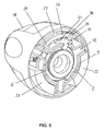
- the mandrel 1 firstly comprises a central piece 2, of axis 3, comprising a rear portion 4 intended to be fixed on a motor shaft of the rotating machine, a central portion 5 having a peripheral toothing 6 oriented axially, and a front part 7 having a frustoconical shape converging towards the front, provided with an external thread 8 on the right.
- the mandrel 1 also comprises a body 9 surrounding the central piece 2 and rotatably mounted relative to the central piece 2.
- the body has a substantially cylindrical casing 10 of axis 11, from which radially project three housing 12 converging towards the front and substantially uniformly distributed on the periphery.
- an opening 13 is formed in the casing 10 of the body 9, approximately one third of the radial distance between two adjacent housings 12.
- the opening 13 is located facing the peripheral toothing 6 of the central piece 2, when the body 9 is mounted on the central piece 2, and is delimited by a front wall 14 and a rear wall orthogonal to the axis 11 of the casing 10 and two side walls 15 perpendicular to the front walls 14 and rear.
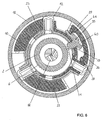
- the body 9 is here formed from a sheet comprising three wings folded on themselves, shown with different hatching in the sectional views ( Figures 6 and 7).
- the mandrel 1 further comprises jaws 16, each being mounted and guided in translation in a housing 12 of the body 9.
- Each jaw 16 has a toothing 17 on its inner face, intended to cooperate with the thread 8 of the central piece 2.
- a clamping ring 18, with axis 19, is mounted around the body 9, in front of the mandrel 1, substantially coaxially.
- the clamping ring 18 comprises a rearwardly open dome-shaped envelope 20 whose inside diameter is slightly greater than the outside diameter of the housings 12 all along the axis, so that the body 9 fits perfectly into the housing. the clamping ring 18.
- the clamping ring 18 comprises three members 21, 22, 23 having in section a crown portion portion coaxial with the casing 20.
- the members 21, 22, 23 are substantially uniformly distributed at the inner periphery of the casing 20 and protrude axially rearwardly beyond the rear edge 24 of the casing 20.
- the members 21, 22, 23 have a radial thickness less than the radial distance between the inner face of the casing 20 of the clamping ring 18 and the outer face of the casing 10 of the body 9, in the assembled state, and a circumferential length less than the circumferential spacing between two housings 12 of the body 9.
- each member 21, 22, 23 extends over a circular arc of approximately 60 to 80 °.
- the clamping ring 18 can pivot around the body 9 at a limited angular amplitude, each member 21, 22, 23 moving in rotation between two extreme positions defined by the abutment against a housing 12.
- the amplitude of this displacement is for example of the order of 20 to 40 °.
- One of the three members 21 comprises two annular grooves 25, each made from a circumferential end of the member 21, substantially on the same circular arc and at the rear edge 24 of the envelope 20, for a distance less than half of the circumferential length of the member 21.
- the rear part of the member 21 forms a lug 26 in the form of a crown portion, connected to the casing 20 by a bridge of material 27.
- the tab 26 has a recess made from its inner face, substantially circumferentially centered, so that the lug 26 has at its end circumferential two lugs, respectively a locking lug 28 and an unlocking lug 29.
- the locking lug 28 has a circumferential length greater than the unlocking pin 29.
- the lug 26 can be elastically deformed in a transverse plane (orthogonal to the axis of the mandrel) so as to bring the lugs closer to or away from each other. 28, 29 of each other. Furthermore, the contour of the lugs 28, 29 is rounded to facilitate their movement and sliding along different surfaces, as will be seen later.
- a metal nose 30 is further mounted inside the clamping ring 18.
- the nose 30 projects in part from the front of the mandrel 1 and is provided with a central opening allowing the jaws 16 and the jaw to pass through. 'tool.
- the mandrel 1 also comprises a rear ring 31 engaged around the rear portion 4 the central piece 2 substantially coaxially.
- the rear ring 31 and the clamping ring 18 are substantially adjacent and of the same diameter in their zone of adjacency, the mandrel 1 thus having a substantially continuous lateral envelope.
- the rear ring 31 comprises a cylindrical portion 32 engaged on the rear portion 4 of the central piece 2, extended towards the outside by a radial portion 33 in the shape of a ring, itself extended outwards by a skirt 34 substantially cylindrical.
- the rear portion 4 of the central piece 2 and the cylindrical portion 32 of the rear ring comprise reciprocal means for locking in rotation and in axial translation.
- the mandrel 1 comprises a locking pin 35 intended to be engaged in the opening 13 of the body 9.
- the locking pin 35 is formed from a metal plate by cutting or embossing, and comprises a front face and a rear face 36 substantially flat and parallel, spaced from each other by a distance substantially equal to the distance between the front walls 14 and rear of the opening 13.
- the locking pin 35 comprises an elongate actuating portion 37 whose inner face 38 is substantially flat and whose outer face 39, generally parallel to the inner face 38, comprises two disk-shaped indentations, forming one a locking housing 40 and the other an unlocking housing 41.
- the housings 40, 41 are spaced from each other in a direction parallel to the front and rear faces of the finger 35 by a distance less than the circumferential distance between the unlocking pin 29 and the locking pin 28.
- upstream and "downstream”, each of which designates one side of the locking pin 35, when viewed from its rear face 36, respectively the side of the unlocking housing 41 and the side locking housing 40.
- the upstream face 42 and the downstream face 43 of the actuating portion 37 of the locking pin 35 are curved and define sliding ramps of the locking lugs 28 and unlocking 29 as will be seen later.
- the locking pin 35 further comprises a locking portion 44 projecting substantially perpendicularly from the inner face 38 of the actuating portion 37, non-centrally but offset downstream.
- the blocking portion 44 comprises a convex downstream face 45 forming a sliding pad, located substantially at the right of the locking housing 40.
- the upstream face 46 comprises a first curved portion forming a recess 47 in which is located the imaginary axis 48 of the connecting fillet 49 in the cylinder portion between the upstream face 46 of the locking portion 44 and the inner face 38 of the actuating portion 37.
- the upstream face 46 then has a curved portion formed by a shoe 50 projecting towards the upstream substantially parallel to the actuating portion 37 and at least partly facing thereof.
- the part of blocking 44 thus has substantially the shape of a crooked hook upstream.
- the free end portion of the locking portion 44 is in the form of a tooth 51 comprising an exhaust face 52 upstream and a blocking face 53 downstream.
- the locking portion 44 of the locking finger 35 is engaged in the opening 13 of the body 9, the inner face 38 of the actuating portion 37 coming into contact with the outer face of the casing 10 of the body 9. Then the clamping ring 18 is engaged around the body 9 and the locking pin 35, so that the tab 26 is located between the same two housings 12 as the locking pin 35.
- mandrel 1 The operation of mandrel 1 is as follows.
- the clamping ring 18 is rotated relative to the central piece 2 in the counterclockwise direction (according to the view of FIG. 6 ).
- the unlocking pin 29 remains placed in the unlocking housing 41 and thereby causes the body 9 to rotate around the central part 2, via the locking finger 35. Since the locking pin 35 is still not in position. contact with the peripheral toothing 6, it does not oppose the relative rotation of the clamping ring assembly 18 - body 9 with respect to the central piece 2.
- the jaws 16, because of the cooperation between their toothing 17 and the thread 8 of the central part 2 are moved in the housing 12 of the body 9 towards the front of the mandrel 1 and brought closer to each other.
- the locking pin 35 can therefore rotate in the opposite direction of the clockwise, this movement being limited by the locking pin 28 connected to the tab 26 elastically deformable. It follows that the locking pin 35 is driven by a reciprocating pivoting movement in a transverse plane, in the manner of a ratchet of a ratchet wheel system, and generates a characteristic pinging sound.
- the locking pin 28 leaves the locking housing 40, then the unlocking pin takes position in the unlocking housing 41, causing the pivoting of the locking pin 35 around the imaginary axis 48 , the tooth 51 thus leaving the contact of the peripheral toothing 6 of the central piece 2.
- the clamping ring 18 can then freely drive the body 9 in rotation in the direction of clockwise, the jaws 16 being moved towards the position where they are retracted inside the mandrel 1 and spaced from each other, the tool can then be removed from the mandrel 1.
Landscapes
- Engineering & Computer Science (AREA)
- Mechanical Engineering (AREA)
- Gripping On Spindles (AREA)
- Clamps And Clips (AREA)
Applications Claiming Priority (1)
| Application Number | Priority Date | Filing Date | Title |
|---|---|---|---|
| FR0502587A FR2883208B1 (fr) | 2005-03-16 | 2005-03-16 | Mandrin porte-outil pour machine tournante, muni de moyens de verrouillage |
Publications (2)
| Publication Number | Publication Date |
|---|---|
| EP1702694A1 true EP1702694A1 (de) | 2006-09-20 |
| EP1702694B1 EP1702694B1 (de) | 2008-05-07 |
Family
ID=35229958
Family Applications (1)
| Application Number | Title | Priority Date | Filing Date |
|---|---|---|---|
| EP06356023A Expired - Lifetime EP1702694B1 (de) | 2005-03-16 | 2006-03-09 | Werkzeugspannfutter für drehende Maschine, mit Verriegelungsmittel |
Country Status (7)
| Country | Link |
|---|---|
| US (1) | US7556269B2 (de) |
| EP (1) | EP1702694B1 (de) |
| CN (1) | CN100562390C (de) |
| AT (1) | ATE394182T1 (de) |
| DE (1) | DE602006001062D1 (de) |
| ES (1) | ES2308702T3 (de) |
| FR (1) | FR2883208B1 (de) |
Families Citing this family (8)
| Publication number | Priority date | Publication date | Assignee | Title |
|---|---|---|---|---|
| FR2883209B1 (fr) * | 2005-03-16 | 2007-05-11 | Amyot Sa Sa Ets | Mandrin porte-outil pour l'equipement d'une machine tournante |
| FR2886183B1 (fr) * | 2005-05-27 | 2007-07-13 | Amyot Sa Sa Ets | Mandrin porte-outil pour l'equipement d'une machine tournante, notamment du type "cle a choc" |
| US7896356B2 (en) * | 2006-04-10 | 2011-03-01 | Shandong Weida Machinery Co., Ltd. | Drill chuck with two-stage gripping |
| FR2941395B1 (fr) | 2009-01-26 | 2014-10-10 | Amyot Ets Sa | Mandrin porte-outil pour l'equipement d'une machine tournante. |
| FR2956051B1 (fr) * | 2010-02-08 | 2012-03-02 | Amyot Ets Sa | Mandrin porte-outil pour l'equipement d'une machine tournante |
| US8616561B2 (en) * | 2012-04-10 | 2013-12-31 | Apex Brands, Inc. | Locking chuck |
| DE102013214019B3 (de) * | 2013-07-17 | 2014-09-11 | Trumpf Werkzeugmaschinen Gmbh + Co. Kg | Spannvorrichtung zum Positionieren von Werkstücken, Werkzeugmaschine mit einer derartigen Spannvorrichtung, Verfahren zum Positionieren von Werkstücken mittels einer derartigen Spannvorrichtung |
| US10603722B2 (en) | 2014-10-10 | 2020-03-31 | Apex Brands, Inc. | Locking chuck |
Citations (9)
| Publication number | Priority date | Publication date | Assignee | Title |
|---|---|---|---|---|
| US4302021A (en) * | 1979-04-14 | 1981-11-24 | Roehm Guenter H | Nonloosening chuck |
| EP0335593A2 (de) * | 1988-03-28 | 1989-10-04 | Matsushita Electric Works, Ltd. | Futter ohne Schlüssel für drehendes Werkzeug |
| EP0590754A1 (de) * | 1992-09-28 | 1994-04-06 | Pi-Chu Lin | Bohrfutter für eine Bohrmaschine |
| EP0864390A2 (de) * | 1997-03-14 | 1998-09-16 | Röhm GmbH | Bohrfutter |
| US6007071A (en) * | 1998-03-09 | 1999-12-28 | Power Tool Holders Incorporated | Chuck with locking body |
| EP1314499A1 (de) * | 2001-11-21 | 2003-05-28 | Metabowerke GmbH | Spannfutter zum schlüssellosen Einspannen von Werkzeugen |
| US20030141676A1 (en) * | 2002-01-31 | 2003-07-31 | Yukiwa Seiko Kabushiki Kaisha | Chuck device |
| US20040217558A1 (en) * | 2001-06-10 | 2004-11-04 | Guimo Yang | Chuck |
| US20040227309A1 (en) * | 2003-05-14 | 2004-11-18 | Rohm Gmbh & Co. Kg | Fast-action drill chuck |
Family Cites Families (16)
| Publication number | Priority date | Publication date | Assignee | Title |
|---|---|---|---|---|
| US573189A (en) * | 1896-12-15 | Ernest ii | ||
| DE7804747U1 (de) * | 1978-02-17 | 1978-06-15 | Roehm, Guenter Horst, 7927 Sontheim | Spannfutter |
| DE3713457C1 (en) * | 1987-04-22 | 1988-09-15 | Roehm Guenter H | Retightening drill chuck |
| DE4238464C1 (de) * | 1992-11-16 | 1994-03-03 | Roehm Guenter H | Selbstspannendes Bohrfutter |
| FR2702975B1 (fr) * | 1993-03-26 | 1995-06-16 | Amyot Ets Sa | Mandrin porte-outil pour l'equipement d'une machine tournante, telle qu'une perceuse. |
| US5741016A (en) * | 1996-10-02 | 1998-04-21 | Power Tool Holders Incorporated | Chuck |
| US6007701A (en) * | 1999-02-16 | 1999-12-28 | Miami University | Method of removing contaminants from used oil |
| DE10101212A1 (de) * | 2001-01-11 | 2002-07-18 | Roehm Gmbh | Bohrfutter |
| JP2003071618A (ja) * | 2001-08-30 | 2003-03-12 | Yukiwa Seiko Inc | チャック装置 |
| FR2847180B1 (fr) * | 2002-11-18 | 2005-02-11 | Amyot Ets Sa | Mandrin porte-outil a systeme de verrouillage |
| CN2582790Y (zh) * | 2002-11-25 | 2003-10-29 | 山东威达机械股份有限公司 | 自锁钻夹头 |
| US7258351B2 (en) * | 2003-04-04 | 2007-08-21 | Robert Bosch Gmbh | Quick-action chuck |
| WO2006099820A1 (de) * | 2005-03-19 | 2006-09-28 | Röhm Gmbh | Bohrfutter |
| DE102005018392B4 (de) * | 2005-04-20 | 2019-10-31 | Röhm Gmbh | Bohrfutter |
| FR2897789B1 (fr) * | 2006-02-27 | 2008-05-09 | Amyot Sa Sa Ets | Mandrin porte-outil pour l'equipement d'une machine tourante muni de moyens de verrouillage radial et axial sequences |
| DE102006011344A1 (de) * | 2006-03-11 | 2007-09-13 | Röhm Gmbh | Bohrfutter |
-
2005
- 2005-03-16 FR FR0502587A patent/FR2883208B1/fr not_active Expired - Fee Related
-
2006
- 2006-02-28 US US11/362,785 patent/US7556269B2/en not_active Expired - Fee Related
- 2006-03-09 DE DE602006001062T patent/DE602006001062D1/de not_active Expired - Lifetime
- 2006-03-09 AT AT06356023T patent/ATE394182T1/de not_active IP Right Cessation
- 2006-03-09 EP EP06356023A patent/EP1702694B1/de not_active Expired - Lifetime
- 2006-03-09 ES ES06356023T patent/ES2308702T3/es not_active Expired - Lifetime
- 2006-03-16 CN CNB2006100717382A patent/CN100562390C/zh not_active Expired - Fee Related
Patent Citations (9)
| Publication number | Priority date | Publication date | Assignee | Title |
|---|---|---|---|---|
| US4302021A (en) * | 1979-04-14 | 1981-11-24 | Roehm Guenter H | Nonloosening chuck |
| EP0335593A2 (de) * | 1988-03-28 | 1989-10-04 | Matsushita Electric Works, Ltd. | Futter ohne Schlüssel für drehendes Werkzeug |
| EP0590754A1 (de) * | 1992-09-28 | 1994-04-06 | Pi-Chu Lin | Bohrfutter für eine Bohrmaschine |
| EP0864390A2 (de) * | 1997-03-14 | 1998-09-16 | Röhm GmbH | Bohrfutter |
| US6007071A (en) * | 1998-03-09 | 1999-12-28 | Power Tool Holders Incorporated | Chuck with locking body |
| US20040217558A1 (en) * | 2001-06-10 | 2004-11-04 | Guimo Yang | Chuck |
| EP1314499A1 (de) * | 2001-11-21 | 2003-05-28 | Metabowerke GmbH | Spannfutter zum schlüssellosen Einspannen von Werkzeugen |
| US20030141676A1 (en) * | 2002-01-31 | 2003-07-31 | Yukiwa Seiko Kabushiki Kaisha | Chuck device |
| US20040227309A1 (en) * | 2003-05-14 | 2004-11-18 | Rohm Gmbh & Co. Kg | Fast-action drill chuck |
Also Published As
| Publication number | Publication date |
|---|---|
| US7556269B2 (en) | 2009-07-07 |
| CN100562390C (zh) | 2009-11-25 |
| ATE394182T1 (de) | 2008-05-15 |
| ES2308702T3 (es) | 2008-12-01 |
| EP1702694B1 (de) | 2008-05-07 |
| DE602006001062D1 (de) | 2008-06-19 |
| US20070252345A1 (en) | 2007-11-01 |
| CN1951614A (zh) | 2007-04-25 |
| FR2883208B1 (fr) | 2007-05-11 |
| FR2883208A1 (fr) | 2006-09-22 |
Similar Documents
| Publication | Publication Date | Title |
|---|---|---|
| EP1419837B1 (de) | Werkzeughalter mit Verriegelungssystem | |
| EP1961531B1 (de) | Befestigungsvorrichtung mit versenkbarem Handhebel und Geräte eine solche Vorrichtung enthaltend | |
| FR2727045A1 (fr) | Dispositif de blocage en rotation pour un outil, monte tournant, d'une machine-outil | |
| FR2898821A1 (fr) | Mandrin porte-foret autoserrant | |
| EP2389264B1 (de) | Werkzeugspannfutter zum vorsehen an einer rotierenden maschine | |
| EP1815926A2 (de) | Werkzeughalter-Dorn für die Ausstattung einer elektrisch umlaufenden Maschine | |
| FR2857080A1 (fr) | Dispositif de verrouillage et raccord de canalisation ainsi equipe | |
| CA2780167A1 (fr) | Dispositif de fixation vissant auto-verrouillable et assemblage ainsi equipe | |
| EP1702694B1 (de) | Werkzeugspannfutter für drehende Maschine, mit Verriegelungsmittel | |
| CH707490A1 (fr) | Clé dynamométrique. | |
| FR2897789A1 (fr) | Mandrin porte-outil pour l'equipement d'une machine tourante muni de moyens de verrouillage radial et axial sequences | |
| EP1702693A1 (de) | Werkzeugspannfutter für eine drehende Maschine | |
| FR2920104A1 (fr) | Mandrin porte-outil pour l'equipement d'une machine tournante | |
| EP0227511B1 (de) | Vorrichtung zum Zusammenklemmen von mindestens zwei Seite an Seite zu verbindenden Teilen und eine Klemmeinheit, die ein Klemmwerkzeug und obige Klemmvorrichtung enthält | |
| EP1883486B1 (de) | Werkzeughalterfutter für eine Rotationsmaschine, im Besonderen für einen Schlagschrauber | |
| FR2881368A1 (fr) | Dispositif de reglage de la semelle d'une scie sauteuse | |
| FR2956051A1 (fr) | Mandrin porte-outil pour l'equipement d'une machine tournante | |
| EP0953778A1 (de) | Schnellmontagemutter bestehend aus zwei Mutterhälften, und Befestigungsvorrichtung insbesondere für Betonschalung mit Verwendung dieser Mutter | |
| EP1858665A1 (de) | Werkzeughalterdorn für eine rotationsmaschine | |
| EP2146661B1 (de) | Vorrichtung zur achsenbeibehaltung eines zahnärztlichen instrumentenarms mit einer von mindestens einem sperrbolzen gekreuzten achse | |
| FR2883210A1 (fr) | Mandrin porte-outil pour l'equipement d'une machine tournante | |
| FR2991218A1 (fr) | Tournevis integrant un limiteur de couple | |
| FR2847181A1 (fr) | Mandrin porte-outil a butee arriere | |
| FR2543628A1 (fr) | Dispositif d'agrafage de deux pieces en aveugle, notamment pour toles de vehicules automobiles | |
| FR2841492A1 (fr) | Outil, notamment cle, dynamometrique comprenant des moyens de verrouillage du reglage du couple de declenchement |
Legal Events
| Date | Code | Title | Description |
|---|---|---|---|
| PUAI | Public reference made under article 153(3) epc to a published international application that has entered the european phase |
Free format text: ORIGINAL CODE: 0009012 |
|
| AK | Designated contracting states |
Kind code of ref document: A1 Designated state(s): AT BE BG CH CY CZ DE DK EE ES FI FR GB GR HU IE IS IT LI LT LU LV MC NL PL PT RO SE SI SK TR |
|
| AX | Request for extension of the european patent |
Extension state: AL BA HR MK YU |
|
| 17P | Request for examination filed |
Effective date: 20061204 |
|
| AKX | Designation fees paid |
Designated state(s): AT BE BG CH CY CZ DE DK EE ES FI FR GB GR HU IE IS IT LI LT LU LV MC NL PL PT RO SE SI SK TR |
|
| GRAP | Despatch of communication of intention to grant a patent |
Free format text: ORIGINAL CODE: EPIDOSNIGR1 |
|
| GRAS | Grant fee paid |
Free format text: ORIGINAL CODE: EPIDOSNIGR3 |
|
| GRAA | (expected) grant |
Free format text: ORIGINAL CODE: 0009210 |
|
| AK | Designated contracting states |
Kind code of ref document: B1 Designated state(s): AT BE BG CH CY CZ DE DK EE ES FI FR GB GR HU IE IS IT LI LT LU LV MC NL PL PT RO SE SI SK TR |
|
| REG | Reference to a national code |
Ref country code: GB Ref legal event code: FG4D Free format text: NOT ENGLISH |
|
| REG | Reference to a national code |
Ref country code: CH Ref legal event code: EP |
|
| REG | Reference to a national code |
Ref country code: IE Ref legal event code: FG4D |
|
| REF | Corresponds to: |
Ref document number: 602006001062 Country of ref document: DE Date of ref document: 20080619 Kind code of ref document: P |
|
| PG25 | Lapsed in a contracting state [announced via postgrant information from national office to epo] |
Ref country code: SI Free format text: LAPSE BECAUSE OF FAILURE TO SUBMIT A TRANSLATION OF THE DESCRIPTION OR TO PAY THE FEE WITHIN THE PRESCRIBED TIME-LIMIT Effective date: 20080507 |
|
| PG25 | Lapsed in a contracting state [announced via postgrant information from national office to epo] |
Ref country code: FI Free format text: LAPSE BECAUSE OF FAILURE TO SUBMIT A TRANSLATION OF THE DESCRIPTION OR TO PAY THE FEE WITHIN THE PRESCRIBED TIME-LIMIT Effective date: 20080507 |
|
| PG25 | Lapsed in a contracting state [announced via postgrant information from national office to epo] |
Ref country code: LV Free format text: LAPSE BECAUSE OF FAILURE TO SUBMIT A TRANSLATION OF THE DESCRIPTION OR TO PAY THE FEE WITHIN THE PRESCRIBED TIME-LIMIT Effective date: 20080507 Ref country code: PL Free format text: LAPSE BECAUSE OF FAILURE TO SUBMIT A TRANSLATION OF THE DESCRIPTION OR TO PAY THE FEE WITHIN THE PRESCRIBED TIME-LIMIT Effective date: 20080507 Ref country code: AT Free format text: LAPSE BECAUSE OF FAILURE TO SUBMIT A TRANSLATION OF THE DESCRIPTION OR TO PAY THE FEE WITHIN THE PRESCRIBED TIME-LIMIT Effective date: 20080507 |
|
| REG | Reference to a national code |
Ref country code: ES Ref legal event code: FG2A Ref document number: 2308702 Country of ref document: ES Kind code of ref document: T3 |
|
| REG | Reference to a national code |
Ref country code: IE Ref legal event code: FD4D |
|
| PG25 | Lapsed in a contracting state [announced via postgrant information from national office to epo] |
Ref country code: IS Free format text: LAPSE BECAUSE OF FAILURE TO SUBMIT A TRANSLATION OF THE DESCRIPTION OR TO PAY THE FEE WITHIN THE PRESCRIBED TIME-LIMIT Effective date: 20080907 |
|
| PG25 | Lapsed in a contracting state [announced via postgrant information from national office to epo] |
Ref country code: SE Free format text: LAPSE BECAUSE OF FAILURE TO SUBMIT A TRANSLATION OF THE DESCRIPTION OR TO PAY THE FEE WITHIN THE PRESCRIBED TIME-LIMIT Effective date: 20080807 Ref country code: IE Free format text: LAPSE BECAUSE OF FAILURE TO SUBMIT A TRANSLATION OF THE DESCRIPTION OR TO PAY THE FEE WITHIN THE PRESCRIBED TIME-LIMIT Effective date: 20080507 Ref country code: CZ Free format text: LAPSE BECAUSE OF FAILURE TO SUBMIT A TRANSLATION OF THE DESCRIPTION OR TO PAY THE FEE WITHIN THE PRESCRIBED TIME-LIMIT Effective date: 20080507 Ref country code: DK Free format text: LAPSE BECAUSE OF FAILURE TO SUBMIT A TRANSLATION OF THE DESCRIPTION OR TO PAY THE FEE WITHIN THE PRESCRIBED TIME-LIMIT Effective date: 20080507 Ref country code: LT Free format text: LAPSE BECAUSE OF FAILURE TO SUBMIT A TRANSLATION OF THE DESCRIPTION OR TO PAY THE FEE WITHIN THE PRESCRIBED TIME-LIMIT Effective date: 20080507 |
|
| PLBI | Opposition filed |
Free format text: ORIGINAL CODE: 0009260 |
|
| PG25 | Lapsed in a contracting state [announced via postgrant information from national office to epo] |
Ref country code: PT Free format text: LAPSE BECAUSE OF FAILURE TO SUBMIT A TRANSLATION OF THE DESCRIPTION OR TO PAY THE FEE WITHIN THE PRESCRIBED TIME-LIMIT Effective date: 20081007 Ref country code: RO Free format text: LAPSE BECAUSE OF FAILURE TO SUBMIT A TRANSLATION OF THE DESCRIPTION OR TO PAY THE FEE WITHIN THE PRESCRIBED TIME-LIMIT Effective date: 20080507 Ref country code: SK Free format text: LAPSE BECAUSE OF FAILURE TO SUBMIT A TRANSLATION OF THE DESCRIPTION OR TO PAY THE FEE WITHIN THE PRESCRIBED TIME-LIMIT Effective date: 20080507 |
|
| PLAX | Notice of opposition and request to file observation + time limit sent |
Free format text: ORIGINAL CODE: EPIDOSNOBS2 |
|
| 26 | Opposition filed |
Opponent name: ROEHM GMBH Effective date: 20090123 |
|
| PG25 | Lapsed in a contracting state [announced via postgrant information from national office to epo] |
Ref country code: EE Free format text: LAPSE BECAUSE OF FAILURE TO SUBMIT A TRANSLATION OF THE DESCRIPTION OR TO PAY THE FEE WITHIN THE PRESCRIBED TIME-LIMIT Effective date: 20080507 Ref country code: BG Free format text: LAPSE BECAUSE OF FAILURE TO SUBMIT A TRANSLATION OF THE DESCRIPTION OR TO PAY THE FEE WITHIN THE PRESCRIBED TIME-LIMIT Effective date: 20080807 |
|
| NLR1 | Nl: opposition has been filed with the epo |
Opponent name: ROEHM GMBH |
|
| PLAF | Information modified related to communication of a notice of opposition and request to file observations + time limit |
Free format text: ORIGINAL CODE: EPIDOSCOBS2 |
|
| BERE | Be: lapsed |
Owner name: ETS AMYOT S.A. Effective date: 20090331 |
|
| PLBB | Reply of patent proprietor to notice(s) of opposition received |
Free format text: ORIGINAL CODE: EPIDOSNOBS3 |
|
| PG25 | Lapsed in a contracting state [announced via postgrant information from national office to epo] |
Ref country code: MC Free format text: LAPSE BECAUSE OF NON-PAYMENT OF DUE FEES Effective date: 20090331 |
|
| REG | Reference to a national code |
Ref country code: FR Ref legal event code: ST Effective date: 20091130 |
|
| PG25 | Lapsed in a contracting state [announced via postgrant information from national office to epo] |
Ref country code: BE Free format text: LAPSE BECAUSE OF NON-PAYMENT OF DUE FEES Effective date: 20090331 |
|
| PG25 | Lapsed in a contracting state [announced via postgrant information from national office to epo] |
Ref country code: FR Free format text: LAPSE BECAUSE OF NON-PAYMENT OF DUE FEES Effective date: 20091123 |
|
| REG | Reference to a national code |
Ref country code: ES Ref legal event code: FD2A Effective date: 20090310 |
|
| REG | Reference to a national code |
Ref country code: FR Ref legal event code: RN |
|
| PG25 | Lapsed in a contracting state [announced via postgrant information from national office to epo] |
Ref country code: ES Free format text: LAPSE BECAUSE OF NON-PAYMENT OF DUE FEES Effective date: 20090310 |
|
| PLCK | Communication despatched that opposition was rejected |
Free format text: ORIGINAL CODE: EPIDOSNREJ1 |
|
| PG25 | Lapsed in a contracting state [announced via postgrant information from national office to epo] |
Ref country code: GR Free format text: LAPSE BECAUSE OF FAILURE TO SUBMIT A TRANSLATION OF THE DESCRIPTION OR TO PAY THE FEE WITHIN THE PRESCRIBED TIME-LIMIT Effective date: 20080808 |
|
| REG | Reference to a national code |
Ref country code: FR Ref legal event code: IC |
|
| PLBN | Opposition rejected |
Free format text: ORIGINAL CODE: 0009273 |
|
| STAA | Information on the status of an ep patent application or granted ep patent |
Free format text: STATUS: OPPOSITION REJECTED |
|
| 27O | Opposition rejected |
Effective date: 20100621 |
|
| PG25 | Lapsed in a contracting state [announced via postgrant information from national office to epo] |
Ref country code: LU Free format text: LAPSE BECAUSE OF NON-PAYMENT OF DUE FEES Effective date: 20090309 |
|
| PG25 | Lapsed in a contracting state [announced via postgrant information from national office to epo] |
Ref country code: HU Free format text: LAPSE BECAUSE OF FAILURE TO SUBMIT A TRANSLATION OF THE DESCRIPTION OR TO PAY THE FEE WITHIN THE PRESCRIBED TIME-LIMIT Effective date: 20081108 |
|
| PG25 | Lapsed in a contracting state [announced via postgrant information from national office to epo] |
Ref country code: TR Free format text: LAPSE BECAUSE OF FAILURE TO SUBMIT A TRANSLATION OF THE DESCRIPTION OR TO PAY THE FEE WITHIN THE PRESCRIBED TIME-LIMIT Effective date: 20080507 |
|
| PG25 | Lapsed in a contracting state [announced via postgrant information from national office to epo] |
Ref country code: CY Free format text: LAPSE BECAUSE OF FAILURE TO SUBMIT A TRANSLATION OF THE DESCRIPTION OR TO PAY THE FEE WITHIN THE PRESCRIBED TIME-LIMIT Effective date: 20080507 |
|
| PGFP | Annual fee paid to national office [announced via postgrant information from national office to epo] |
Ref country code: CH Payment date: 20120215 Year of fee payment: 7 |
|
| PGFP | Annual fee paid to national office [announced via postgrant information from national office to epo] |
Ref country code: NL Payment date: 20120222 Year of fee payment: 7 |
|
| REG | Reference to a national code |
Ref country code: NL Ref legal event code: V1 Effective date: 20131001 |
|
| REG | Reference to a national code |
Ref country code: CH Ref legal event code: PL |
|
| PG25 | Lapsed in a contracting state [announced via postgrant information from national office to epo] |
Ref country code: CH Free format text: LAPSE BECAUSE OF NON-PAYMENT OF DUE FEES Effective date: 20130331 Ref country code: LI Free format text: LAPSE BECAUSE OF NON-PAYMENT OF DUE FEES Effective date: 20130331 |
|
| PG25 | Lapsed in a contracting state [announced via postgrant information from national office to epo] |
Ref country code: NL Free format text: LAPSE BECAUSE OF NON-PAYMENT OF DUE FEES Effective date: 20131001 |
|
| PGFP | Annual fee paid to national office [announced via postgrant information from national office to epo] |
Ref country code: DE Payment date: 20140317 Year of fee payment: 9 |
|
| PGFP | Annual fee paid to national office [announced via postgrant information from national office to epo] |
Ref country code: IT Payment date: 20140318 Year of fee payment: 9 |
|
| PGFP | Annual fee paid to national office [announced via postgrant information from national office to epo] |
Ref country code: GB Payment date: 20140314 Year of fee payment: 9 |
|
| REG | Reference to a national code |
Ref country code: DE Ref legal event code: R119 Ref document number: 602006001062 Country of ref document: DE |
|
| GBPC | Gb: european patent ceased through non-payment of renewal fee |
Effective date: 20150309 |
|
| PG25 | Lapsed in a contracting state [announced via postgrant information from national office to epo] |
Ref country code: IT Free format text: LAPSE BECAUSE OF NON-PAYMENT OF DUE FEES Effective date: 20150309 |
|
| PG25 | Lapsed in a contracting state [announced via postgrant information from national office to epo] |
Ref country code: GB Free format text: LAPSE BECAUSE OF NON-PAYMENT OF DUE FEES Effective date: 20150309 Ref country code: DE Free format text: LAPSE BECAUSE OF NON-PAYMENT OF DUE FEES Effective date: 20151001 |