EP1702838A2 - Kit pour transformer un véhicule routier en un véhicule pour la neige - Google Patents
Kit pour transformer un véhicule routier en un véhicule pour la neige Download PDFInfo
- Publication number
- EP1702838A2 EP1702838A2 EP06111052A EP06111052A EP1702838A2 EP 1702838 A2 EP1702838 A2 EP 1702838A2 EP 06111052 A EP06111052 A EP 06111052A EP 06111052 A EP06111052 A EP 06111052A EP 1702838 A2 EP1702838 A2 EP 1702838A2
- Authority
- EP
- European Patent Office
- Prior art keywords
- ski
- assembly according
- vehicle
- assembly
- adaptation
- Prior art date
- Legal status (The legal status is an assumption and is not a legal conclusion. Google has not performed a legal analysis and makes no representation as to the accuracy of the status listed.)
- Withdrawn
Links
Images

Classifications
-
- B—PERFORMING OPERATIONS; TRANSPORTING
- B62—LAND VEHICLES FOR TRAVELLING OTHERWISE THAN ON RAILS
- B62K—CYCLES; CYCLE FRAMES; CYCLE STEERING DEVICES; RIDER-OPERATED TERMINAL CONTROLS SPECIALLY ADAPTED FOR CYCLES; CYCLE AXLE SUSPENSIONS; CYCLE SIDECARS, FORECARS, OR THE LIKE
- B62K13/00—Cycles convertible to, or transformable into, other types of cycles or land vehicle
Definitions
- the object of the present invention is a conversion assembly for a road vehicle, for example a two wheeler, such as a bike or a motorbike, wherein said assembly is suitable for converting said vehicle into a snow vehicle, that is, a vehicle suitable for moving forward on a snow covered roadbed.
- Vehicles suitable for moving forward on a snow covered roadbed comprising a rear wheel, actuated by pedals or motor, sided by two skis, and a front ski connected to a handlebar for determining the vehicle direction.
- such assemblies are suitable for being mounted in a simple manner by the user on a road vehicle, for example after removing the front wheel thereof, for transforming the road vehicle into a snow vehicle.
- the object of the present invention is to overcome the disadvantages mentioned above with reference to the prior art.
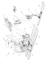
- FIG. 1 shows a snow vehicle comprising a conversion assembly according to an embodiment of the present invention
- figure 2 shows a detail of the vehicle of figure 1 relating to a rear conversion unit of the assembly
- figure 3 shows a plan view of a plate of the rear conversion unit of figure 2;
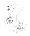
- figure 4 shows means for orientating the rear conversion unit of figure 1;
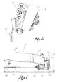
- figure 5 shows a clamping unit of a front conversion unit of the assembly of figure 1.
- reference numeral 1 globally indicates a snow vehicle, that is, a vehicle suitable for moving on a snow covered roadbed.
- Vehicle 1 comprises at least one wheel 2, suitable for rotating about a wheel axis X-X. Said wheel is suitable for cooperating with the snow covered roadbed for moving the vehicle.
- Said snow vehicle comprises a frame 3 for the driver's support, coupled to said wheel 2.
- said frame 3 comprises a first bar 3a and a second bar 3b, converging with each other towards a connecting zone of the vehicle wheel.
- said snow vehicle further comprises a fork 4, coupled to said frame 3, so as to rotate about a fork axis Z-Z.
- vehicle 1 comprises a handlebar 6, coupled to fork 4, suitable for being gripped by a driver for determining the vehicle forward direction.
- vehicle 1 comprises a saddle 8, coupled to frame 3, suitable for the driver's seat.
- Vehicle 1 further comprises actuating means suitable for influencing said wheel for placing it into rotation.
- said actuating means comprise a pair of pedals 12 and driving gears 13 for moving the wheel.
- said actuating means comprise a motor, for example electrical or fuel-powered, suitable for being controlled by the driver.
- the conversion assembly comprises at least one ski 14 suitable for supporting and for making said vehicle 1 sliding on said snow covered roadbed.
- said assembly comprises a pair of skis 14.
- said assembly comprises connecting means suitable for connecting said ski 14 to said frame 3.
- the connecting means comprise a plate 16 suitable for being connected to ski 14 and to frame 3.
- Plate 16 determines, with the prevailing extension thereof, a plate plane.
- said connecting means comprise a first adaptation unit 18 (figure 2), suitable for connecting said plate 16 to said first bar 3a of frame 3.
- the first adaptation unit comprises a first adaptation element 20 (figure 3), connectable in a fixed manner to plate 16 and turnable about a first adaptation axis, perpendicular to said plate 16.
- the first adaptation unit comprises a hooking flange 22 suitable for hooking to said bar 3a, for example tightening about the outer surface of a portion of said bar.
- said hooking flange 22 comprises a first half-body 24a and a second half-body 24b suitable for tightening about a bar of different diameter or thickness, for example by a bolt system.
- the first adaptation unit 18 preferably comprises a soft insert, for example made of leather, suitable for being arranged between flange 22 and the bar, for preventing scratches and the like.
- the first adaptation unit 18 comprises a spacer element 26 suitable for connecting said adaptation element 20 to said flange 22 so as to adjust the distance between said adaptation element 20 and said flange 22, for example by a bolt and shim system.
- said spacer element 26 is suitable for adjusting the arrangement of said flange 22 by a rotation about a second adaptation axis, perpendicular to said first adaptation axis.
- said connecting means comprise a second adaptation unit 28 (figure 3), suitable for connecting said plate 16 to said second bar 3b of frame 3.
- Said second adaptation unit 28 is structurally and functionally similar to said first adaptation unit 18.
- said connecting means comprise elastic connecting means, that is, means suitable for deforming, for example for following the irregularities of the snow covered roadbed or following the weight of the frame or of the driver.
- said elastic means comprise at least one laminated spring 30 operatively connected to said plate 16 and to said ski 14.
- each ski 14 is connected to said plate 16 by two laminated springs.
- said laminated spring 30 comprises an initial portion 32 (figure 2) for the connection to plate 16, an end portion 34 for the connection to the ski, and an intermediate flexible portion 36.
- Said flexible portion 36 is arched and arranged so as to face the convex portion thereof towards the front side of the vehicle.
- said connecting means further comprise means for orientating the ski suitable for adjusting and fixing the ski convergence and/or sharp edge.
- ski axis the plane determined by the ski sole is defined as ski plane, while the axis along which the ski exhibits the prevailing extension thereof is defined as ski axis.
- Convergence is the angle formed by the ski axis with the forward movement axis on the ski plane.
- Sharp edge is the angle formed by the ski plane with the horizontal plane on which the vehicle proceeds. Intuitively, the sharp edge is the rotation of the ski about the longitudinal ski axis thereof.
- Said orientation means suitable for adjusting and fixing the ski convergence comprise an adjustment element 40 fixed to ski 14 at the top surface thereof, so as to be turnable about a convergence axis perpendicular to the ski plane.
- said adjustment element 40 is fixed to the ski in a fixing point 42 (figure 4), for example by a screw.
- Said adjustment means 40 comprises slots 44a, 44b arranged at the ends of said adjustment means.
- Said slots are suitable for seating a fixing element 46, for example a screw, suitable for fixing the adjustment element 40 to the ski in a predetermined position.
- said laminated spring 30 is directly connected to said adjustment means 40.
- Said orientation means suitable for adjusting and fixing the ski sharp edge comprise an adjustment body 50 hinged to the ski turnable about said longitudinal ski axis or an axis parallel to said ski axis.
- Said body 50 is fixable in a predetermined position rotated relative to said ski plane by a fixing element, for example a screw, movable into a slot of a block 52 integral to the ski 14.
- the laminated spring 30 is directly hinged to said adjustment body 50.
- said adjustment means 40 comprises said block 52 and said body 50 couples to said adjustment element 40.
- said assembly comprises a front conversion unit comprising a front ski 60 (figure 1) and front connecting means for the connection of said front ski 60 to the vehicle fork.
- said front connecting means comprise a clamping unit 62 suitable for connecting said front ski to the fork tines.
- Said clamping unit 62 is suitable for being associated to tines having different nominal shape and size, for example diameter or thickness.
- said front connecting means comprise a front laminated spring 64, for example consisting of two sided elements, connected to said clamping unit 62 and to said front ski 60.
- said connecting means comprise said orientation means associated to said front ski.
- said connecting means comprise shock absorbing means suitable for absorbing the influence of the snow covered roadbed on the inclination of the front ski.
- said absorbing means comprise a dual effect shock absorber 70 connected at an end to the ski and, at the other end, to the front laminated spring 64.
- said assembly comprises two rear conversion units, each comprising a plate 16, a rear ski 14 and connecting means, and a front conversion unit.
- the front wheel of the road vehicle is removed from the fork and the tines thereof are associated to the front conversion unit, comprising the clamping unit 62, to be connected to the fork tines, the front laminated spring 64 and the front ski 60.
- plate 16 is associated to the first bar 3a and to the second bar 3b of frame 3.
- the first adaptation unit is connected to the first bar 3a and the second adaptation unit is connected to the second bar 3b.
- the adaptation units are turnable relative to plate 16 so as to arrange ski 14 substantially parallel to the roadbed, irrespective of the specific frame structure, that is, irrespective of the inclination of the bars forming said frame.
- flanges 22 are suitable for hooking said bars irrespective of the diameter or thickness thereof, and are turnable, to mount plate 16 so as to arrange ski 14 substantially parallel to the roadbed.
- ski convergence is adjusted and fixed by operating on said orientation means.
- the fixing element 46 is released and the ski is rotated about the convergence axis perpendicular to the ski plane. Once the convergence has been adjusted as desired, the fixing element 46 is screwed into slot 44a, thus locking the ski inclination.
- the ski sharp edge is adjusted and fixed by operating on said orientation means.
- the fixing element is screwed into the slot of block 52, thus locking said sharp edge.
- the rear vehicle wheel may be too low, that is, too immersed into the snow covered roadbed, or too high, that is, such as to slightly touch or even not touch the roadbed, and therefore the proper vehicle forward movement is not ensured.
- connection between the rear laminated springs and plate 16 is adjusted, raising or lowering the rear wheel.
- each rear conversion unit can be disconnected from the frame by operating on the adaptation units, leaving the ski orientation conditions unchanged, for a subsequent installation.
- the assembly according to the present invention allows converting a road vehicle into a snow vehicle irrespective of the structural features of the frame of a large number of road vehicles, such as bikes.
- the assembly allows being coupled to the vehicle without structurally modifying said vehicle, that is, for example without making holes on the frame.
- said assembly allows a ski orientation according to the user's needs or preferences.
- said ski orientation remains fixed even when the conversion units are disconnected from the frame, thus avoiding the need of adjusting the orientation at every new conversion of the vehicle.
Landscapes
- Engineering & Computer Science (AREA)
- Mechanical Engineering (AREA)
- Fittings On The Vehicle Exterior For Carrying Loads, And Devices For Holding Or Mounting Articles (AREA)
Applications Claiming Priority (1)
| Application Number | Priority Date | Filing Date | Title |
|---|---|---|---|
| ITBS20050039 ITBS20050039A1 (it) | 2005-03-15 | 2005-03-15 | Assieme di conversione di un veicolo da strada in un veicolo da neve e veicolo da neve convertito |
Publications (1)
| Publication Number | Publication Date |
|---|---|
| EP1702838A2 true EP1702838A2 (fr) | 2006-09-20 |
Family
ID=36593227
Family Applications (1)
| Application Number | Title | Priority Date | Filing Date |
|---|---|---|---|
| EP06111052A Withdrawn EP1702838A2 (fr) | 2005-03-15 | 2006-03-13 | Kit pour transformer un véhicule routier en un véhicule pour la neige |
Country Status (2)
| Country | Link |
|---|---|
| EP (1) | EP1702838A2 (fr) |
| IT (1) | ITBS20050039A1 (fr) |
Cited By (2)
| Publication number | Priority date | Publication date | Assignee | Title |
|---|---|---|---|---|
| RU2518917C2 (ru) * | 2012-09-18 | 2014-06-10 | Алим Таусолтанович Созаев | Трансформируемый детский велосипед |
| EP2809566A4 (fr) * | 2012-02-03 | 2015-08-19 | Bassein Simon | Vélo des neiges à 3 skis |
Citations (10)
| Publication number | Priority date | Publication date | Assignee | Title |
|---|---|---|---|---|
| US573034A (en) | 1896-12-15 | Snow-shoe attachment for bicycles | ||
| US773959A (en) | 1904-05-02 | 1904-11-01 | Richard Adolf Meissner | Sleigh-runner attachment for bicycles. |
| CH76384A (de) | 1917-03-20 | 1918-05-01 | Andreas Paulick | Schlittenfahrzeug mit mechanischem Antrieb |
| US1337396A (en) | 1919-04-10 | 1920-04-20 | Eiselt Robert Otto | Bicycle attachment |
| US3561777A (en) | 1969-04-09 | 1971-02-09 | Harry F Geis | Bicycle with support skis |
| US3783959A (en) | 1972-03-06 | 1974-01-08 | R Krume | Ski vehicle with improved front support means |
| US3814198A (en) | 1971-12-16 | 1974-06-04 | V Seiler | Ski cycle |
| US3884484A (en) | 1973-05-01 | 1975-05-20 | Emanuel J Uhlyarik | Conversion system for pedal-operated cycles |
| US3931983A (en) | 1972-08-28 | 1976-01-13 | The Raymond Lee Organization, Inc. | Snow cycle |
| EP0799763A2 (fr) | 1996-04-03 | 1997-10-08 | Corimba S.n.c. di Bettini Cesare & C. | Véhicule pour la neige à propulsion actionné par pédales |
-
2005
- 2005-03-15 IT ITBS20050039 patent/ITBS20050039A1/it unknown
-
2006
- 2006-03-13 EP EP06111052A patent/EP1702838A2/fr not_active Withdrawn
Patent Citations (10)
| Publication number | Priority date | Publication date | Assignee | Title |
|---|---|---|---|---|
| US573034A (en) | 1896-12-15 | Snow-shoe attachment for bicycles | ||
| US773959A (en) | 1904-05-02 | 1904-11-01 | Richard Adolf Meissner | Sleigh-runner attachment for bicycles. |
| CH76384A (de) | 1917-03-20 | 1918-05-01 | Andreas Paulick | Schlittenfahrzeug mit mechanischem Antrieb |
| US1337396A (en) | 1919-04-10 | 1920-04-20 | Eiselt Robert Otto | Bicycle attachment |
| US3561777A (en) | 1969-04-09 | 1971-02-09 | Harry F Geis | Bicycle with support skis |
| US3814198A (en) | 1971-12-16 | 1974-06-04 | V Seiler | Ski cycle |
| US3783959A (en) | 1972-03-06 | 1974-01-08 | R Krume | Ski vehicle with improved front support means |
| US3931983A (en) | 1972-08-28 | 1976-01-13 | The Raymond Lee Organization, Inc. | Snow cycle |
| US3884484A (en) | 1973-05-01 | 1975-05-20 | Emanuel J Uhlyarik | Conversion system for pedal-operated cycles |
| EP0799763A2 (fr) | 1996-04-03 | 1997-10-08 | Corimba S.n.c. di Bettini Cesare & C. | Véhicule pour la neige à propulsion actionné par pédales |
Cited By (2)
| Publication number | Priority date | Publication date | Assignee | Title |
|---|---|---|---|---|
| EP2809566A4 (fr) * | 2012-02-03 | 2015-08-19 | Bassein Simon | Vélo des neiges à 3 skis |
| RU2518917C2 (ru) * | 2012-09-18 | 2014-06-10 | Алим Таусолтанович Созаев | Трансформируемый детский велосипед |
Also Published As
| Publication number | Publication date |
|---|---|
| ITBS20050039A1 (it) | 2006-09-16 |
Similar Documents
| Publication | Publication Date | Title |
|---|---|---|
| US7127966B2 (en) | Aerobar assembly | |
| US8424894B2 (en) | Bicycle frame dropouts and methods | |
| US7207914B2 (en) | Bicycle rear derailleur guard | |
| US5855388A (en) | Floating gauge mount for motorcycle | |
| US20090072512A1 (en) | Bicycle rear suspension system | |
| EP2093137A1 (fr) | Dispositif de réglage de l'inclinaison d'une fourche avant d'un véhicule à deux ou trois roues | |
| US8991543B2 (en) | Straddle type vehicle | |
| US7644642B2 (en) | Handlebar top clamp for steering systems | |
| US20070241531A1 (en) | Stem assembly for a bicycle | |
| US6955373B2 (en) | Shock-absorbing frame for bicycle. | |
| US8522929B2 (en) | Bicycle rim brake assembly | |
| EP1702838A2 (fr) | Kit pour transformer un véhicule routier en un véhicule pour la neige | |
| EP1877300A1 (fr) | Extension de guidon | |
| US8011716B2 (en) | Motorcycle with cantilevered front windshield | |
| US4226463A (en) | Windshield mounting assembly | |
| CN114555457B (zh) | 用于骑行车的低行程后轮悬架系统 | |
| US20240059369A1 (en) | Two-wheeled vehicle having rear suspension with adjustable leverage curve progression | |
| WO2003002400A1 (fr) | Retroviseur pour bicyclette | |
| WO2008155587A3 (fr) | Véhicule routier à écartement variable ayant plus de trois roues | |
| US20040238298A1 (en) | Multifunction braking and suspension device for a motorcycle or other vehicle | |
| US979032A (en) | Shock-absorber for vehicles. | |
| AU2018100838A4 (en) | The present invention relates to a bicycle handlebar 'cycling aid device mount'; whereby the inclusion of a set of unique, fully articulated Elbows, Arms, and Levers, secures practically any size cycling aid device forward of the bicycle handlebars and over a large stable platform base; affording the rider a custom viewing angle of that cycling aid device in full view of the rider without the need for the rider to dip or lower their head in order to view the cycling aid device; affording the rider the ability to maintain continual focus on the road/trail ahead, promoting a safe cycling edict | |
| US20260062080A1 (en) | Preload adjustable shock-absorbing seatpost assembly | |
| FR2899867A1 (fr) | Dispositif pour la filtration des vibrations et des chocs sur un guidon de vehicule | |
| US11312439B2 (en) | Adjustable seat assembly for a motorcycle, and motorcycle |
Legal Events
| Date | Code | Title | Description |
|---|---|---|---|
| PUAI | Public reference made under article 153(3) epc to a published international application that has entered the european phase |
Free format text: ORIGINAL CODE: 0009012 |
|
| AK | Designated contracting states |
Kind code of ref document: A2 Designated state(s): AT BE BG CH CY CZ DE DK EE ES FI FR GB GR HU IE IS IT LI LT LU LV MC NL PL PT RO SE SI SK TR |
|
| AX | Request for extension of the european patent |
Extension state: AL BA HR MK YU |
|
| PUAL | Search report despatched |
Free format text: ORIGINAL CODE: 0009013 |
|
| PUAF | Information related to the publication of a search report (a3 document) modified or deleted |
Free format text: ORIGINAL CODE: 0009199SEPU |
|
| STAA | Information on the status of an ep patent application or granted ep patent |
Free format text: STATUS: THE APPLICATION IS DEEMED TO BE WITHDRAWN |
|
| AK | Designated contracting states |
Kind code of ref document: A3 Designated state(s): AT BE BG CH CY CZ DE DK EE ES FI FR GB GR HU IE IS IT LI LT LU LV MC NL PL PT RO SE SI SK TR |
|
| AX | Request for extension of the european patent |
Extension state: AL BA HR MK YU |
|
| D17D | Deferred search report published (deleted) | ||
| 18D | Application deemed to be withdrawn |
Effective date: 20081001 |