EP1702850A2 - Vorrichtung zum Einklappen von Steigen - Google Patents
Vorrichtung zum Einklappen von Steigen Download PDFInfo
- Publication number
- EP1702850A2 EP1702850A2 EP06075458A EP06075458A EP1702850A2 EP 1702850 A2 EP1702850 A2 EP 1702850A2 EP 06075458 A EP06075458 A EP 06075458A EP 06075458 A EP06075458 A EP 06075458A EP 1702850 A2 EP1702850 A2 EP 1702850A2
- Authority
- EP
- European Patent Office
- Prior art keywords
- engagement
- folding
- wall
- fingers
- crate
- Prior art date
- Legal status (The legal status is an assumption and is not a legal conclusion. Google has not performed a legal analysis and makes no representation as to the accuracy of the status listed.)
- Granted
Links
Images





Classifications
-
- B—PERFORMING OPERATIONS; TRANSPORTING
- B65—CONVEYING; PACKING; STORING; HANDLING THIN OR FILAMENTARY MATERIAL
- B65B—MACHINES, APPARATUS OR DEVICES FOR, OR METHODS OF, PACKAGING ARTICLES OR MATERIALS; UNPACKING
- B65B69/00—Unpacking of articles or materials, not otherwise provided for
-
- B—PERFORMING OPERATIONS; TRANSPORTING
- B65—CONVEYING; PACKING; STORING; HANDLING THIN OR FILAMENTARY MATERIAL
- B65B—MACHINES, APPARATUS OR DEVICES FOR, OR METHODS OF, PACKAGING ARTICLES OR MATERIALS; UNPACKING
- B65B43/00—Forming, feeding, opening or setting-up containers or receptacles in association with packaging
- B65B43/26—Opening or distending bags; Opening, erecting, or setting-up boxes, cartons, or carton blanks
- B65B43/265—Opening, erecting or setting-up boxes, cartons or carton blanks
Definitions
- the present invention relates to a device for folding-in folding crates.
- folding crates can be embodied with a locking system. They may be folding crates of a system with multiple wall dimensions, wherein the locking means are arranged in two oppositely located walls. They may for instance be crates of the so-called Europool-system.
- a known device for folding-in crates comprises a belt conveyor for conveying the folding crates through the device, and unlocking means which are arranged above the belt conveyor and which can travel along with the belt conveyor to unlock the locking means. During continuous conveyance of the folding crates the locking means are engaged from above to relieve the locking.
- the device is suitable for folding-in folding crates which all have the same crate height. For a different crate height the device has to be manually adjusted.
- the invention provides a device for folding-in folding crates, wherein in two opposite first walls said folding crates are provided with locking means to lock the unfolded position, in cooperation with connecting second walls, wherein the device comprises a conveyor for moving the crates through the device according to a process path, as well as deactivation means to deactivate the locking means by engaging the locking means, and defining means to define a height dimension of folding crates, wherein an engagement level of the deactivation means with respect to a reference plane, such as the conveyor, is adjustable in response to a height level defined by the defining means. Because the engagement height is adjustable in response to the defined height dimension, the deactivation means can engage each individual crate at the correct engagement height. Thereby the device can fold-in crates with mutually different and/or varying crate heights.
- the deactivation means comprise first engagement means for engagement of the operating parts of the locking means.
- the first engagement means comprise first fingers which are moveable with respect to each other between a first, receded spreaded position and a second, close gripping position in which with one end the fingers can engage the operating parts of the locking means for deactivation thereof.
- the first fingers can extend into operating eyes of the folding crate to relieve the lock.
- first fingers are moveable in a plane parallel to a support surface of the conveyor, then the fingers transversely engage an unfolded first wall and easily operate the operating parts located therein, which are moveable in a direction parallel to the bottom of a folding crate.
- the device comprises second engagement means for abutment against, or biasing by engagement, a locked first wall of a folding crate in the direction of the folded-in position. Because of the bias, for instance by elastically bending the first wall in the form of an arc, the first wall can vigorously fold in to its folded-in position after the lock has been relieved.
- an extreme position of the second engagement means in the direction of engagement is adjustable to adjust the bias of the first wall
- varying bending properties of the first wall can be taken into account in order to achieve the required bias.
- the bending properties can vary for instance as a consequence of a change in temperature of the crate, caused by washing the crate with heated water.
- the engagement height of the second engagement means relative to the reference plane is adjustable in response to a height dimension defined by the defining means.
- the second engagement means are adapted to engage near a free upper edge of a first wall of a folding crate, preferably in the centre of said wall. By engaging the free upper edge the first wall can be brought in an arched biased condition with little force.
- the second engagement means comprise a second finger which is moveable between a first, receded position, and a second, protruding position in which with one end the second finger can engage a first wall of a folding crate.
- the second finger is preferably moveable in a plane parallel to a bearing surface of the conveyor.
- first engagement means and the second engagement means are connected with the same holder so as to travel along with the holder, wherein the distance between the first engagement means and the second engagement means in the direction of engagement is preferably attuned to the distance in the direction of engagement between a first wall and the locking means in the first wall of a folding crate, the first engagement means can be held automatically at the correct engagement position while the first wall is biased to the folded-in position.
- the holder can be displaceable along a guide which is arranged transversely to the process path for positioning the engagement parts with respect to the reference plane.
- the first engagement means and the second engagement means can each be connected with their own a holder.
- the guide is a straight guide which is arranged transversely to the reference plane for positioning the engagement parts with respect to the reference plane.
- the deactivation means can be displaced according to a straight line along the upright first walls of folding crates if the guide is a straight guide which is arranged perpendicularly to the reference plane.
- the device comprises means for defining the absolute position, electronic control means and drive means for the displacement of the holder, wherein the electronic control means are adapted to displace the holder along the guide in response to the means for defining the absolute position and the means for defining the height level.
- a correct engagement of the locking means can be enhanced if said device comprises a brake to detain a folding crate in a deactivation position and to position same on the conveyor.
- the defining means comprise a plurality of presence detectors for detection of the presence of a wall of a folding crate, wherein the presence detectors are arranged at various heights with respect to the reference plane, preferably at the heights which correspond with standard heights of folding crates.
- the device may comprise folding-in means to fold-in the second walls after folding-in the first walls.
- the device comprises checking means to check the folded-in position of the first and/or second walls, then a folding-in operation can be repeated if necessary to achieve the folded-in position.
- the device can comprise ejection means for ejecting folding crates from the process path in response to the checking means. For instance an incompletely folded-in crate can be ejected prematurely from the continuous process path so that only completely folded-in crates leave the device at the end of the process path.
- the first walls of folding crates which are supplied one after the other by the belt conveyor can be folded-in from the outside of the folding crates if the deactivation means are arranged at both sides of the process path to fold-in oppositely disposed first walls of a folding crate transversely to the direction of conveyance.
- the device can fold-in crates with mutually different crate widths if the distance between the mutual deactivation means is adjustable according to the distance between the first walls transversely to the direction of conveyance.
- the invention provides a device for folding-in folding crates, wherein, in two opposite first walls, said folding crates are provided with locking means to lock the unfolded position, in cooperation with connecting second walls, wherein the device comprises holding means to hold the folding crate during folding-in, as well as deactivation means to deactivate the locking means by engagement of the locking means, said deactivation means comprising first engagement means to engage operating parts of the locking means, wherein the first engagement means comprise fingers or pins which are moveable with respect to each other between a first, receded spreaded position in which the fingers are disposed at a mutual distance which is larger than the mutual distance of the operating means, and a second, close engagement position, at which the fingers have arrived with one end at the location of operating parts.
- the fingers are moveable further towards each other from the second position to a third position in which they exert a displacing force on the operating means of the locking means for deactivation thereof.
- the fingers are moveable from the first to the third position in one continuous movement.
- the fingers are moveable in a plane parallel to the bottom of the crate.
- the fingers are arranged for movement by means of swivelling, in particular by rotation.
- the operating means comprise operating eyes or the like, into which the fingers can extend.
- the fingers can be provided with engagement ends, which diverge with respect to each other in the third position. This enhances the engagement of the operating means, as well as moving same away from the fingers during the folding operation of the wall.
- the engagement ends are arranged at an obtuse angle with respect to a connecting part of the respective finger. In the third position the connecting parts of the fingers can then extend parallel to each other.
- the folding crate 1 as shown in figures 1A-D has a bottom 2, two longitudinal walls 3 and two transverse walls 4, which walls are pivotally connected with the bottom 2.
- the crate 1 as shown in this example is of the Europool-type, with a bottom size of 400 x 600 mm.
- the longitudinal walls 3 are provided with operable closing means 5, which can be pulled towards each other by pull eyes 7 in the direction A so as to relieve a lock between the upright edges of the encountering walls 3 and 4.
- the closing means 5 are adapted to become automatically active, by snapping, when said edges of the walls 2 and 3 have been correctly brought against each other.
- Europool-folding crates are available in different bottom sizes and various crate heights.
- the illustrated folding crate 1 has a crate height of 150 mm. The distance between the free upper end 6 and the pull eyes 7 of the longitudinal walls 3 is the same for all crate heights.
- FIG. 1A the folding crate 1 is illustrated in folded-in condition, wherein the transverse walls 4 are disposed over the longitudinal walls 3.
- FIG. 1B up to and including 1D the successive steps of folding-in the folding crate 1 are illustrated.
- FIG 1B the walls 3, 4 of the folding crate 1 are completely upright.
- the folding-in device 10 comprises a metal frame 11 with a belt conveyor 12 to convey the folding crates 1 in the direction D through the folding-in device 10.
- guides 17 are arranged to guide the folding crates 1.
- the guides 17 are mutually attuned transversely to the direction of conveyance D for abutment against the longitudinal sides 3 of folding crates 1.
- a measuring station 13 for the crate height
- a folding-in station 18 for the longitudinal wall
- two first brakes 19 two second brakes 20
- a holder 21 for a curtain 22.
- a checking station 70 Downstream of the curtain 22 a checking station 70 is arranged, also provided with two third brakes 71.
- the checking station 70 is provided with a crate ejector 72 to remove incorrectly folded-in crates transversely to the belt conveyor 12.
- the measuring station 13 comprises an upright bearing rod 14.
- Height-adjustable holders 40 (four in this example) are attached to the bearing rods 14, in which various electronic photocells (presence detectors) are incorporated.
- the heights of the photocells differ mutually so as to determine the heights of folding crates 1 by detection of the side walls.
- the folding-in station 18 for the longitudinal walls is set up with a metal portal 15 which extends along the belt conveyor 12 and which is attached to the frame 11.
- a metal portal 15 which extends along the belt conveyor 12 and which is attached to the frame 11.
- upright servo-pneumatic positioning cylinders 16 are arranged between the upright parts of the portal 15 and the belt conveyor 12 for accurate height adjustment of two further elucidated unlocking grippers 50 (deactivation means) in the direction G for engagement of the pull eyes 7 in the longitudinal walls 3 of a folding crate 1.
- the positioning cylinders 16 each have an electronic absolute distance meter, which is not shown, to determine the position of the unlocking grippers 50 in the direction G along the positioning cylinder 16.
- the first brakes 19 each have a first blocking plate 60 which is displaceable by a pneumatic cylinder 41 in the direction E transversely to the direction of conveyance D between a protruding position, in which the first blocking plate 60 can contact a leading side wall of a folding crate 1, and a (dotted) withdrawn position, in which a folding crate 1 can freely pass the first brakes 19.
- the distance in the direction of conveyance D between the first blocking plates 60 and the unlocking grippers 50 is attuned to the width of a folding crate 1, such that a folding crate 1, which is blocked by the first brakes 19, is positioned with its pull eyes 7, right across the unlocking grippers 50 when viewed from above.
- Each of the second brakes 20 also comprises a second blocking plate 61 which is displaceable by means of a pneumatic cylinder 42 in the direction F transversely to the direction of conveyance D between a protruding position, in which the second blocking plate 61 above the belt conveyor 12 can contact a leading end of a folding crate 1, and a (dotted) retracted position, in which a folding crate 1 can freely pass the second brakes 20.
- the distance between the first blocking plates 60 and the second blocking plates 61 is attuned in the direction of conveyance D, such that a folding crate can be enclosed with a small clearance between the first blocking plates 60 and the second blocking plates 61.
- the second brakes 20 provide a first positioning of an inters pace or gap 80 between two successive folding crates 1, so that after activation of the second brakes 20 the first blocking plates 60 can extend into the gap 62 via the curvatures of the corners of the folding crate 1. Thereby the folding crate 1 is accurately positioned with respect to the unlocking grippers 50 by the first brakes 19.
- FIG 4A illustrates one of the two unlocking grippers 50 in more detail.
- the unlocking gripper 50 comprises a pneumatic cylinder 31 which at the rear side is attached to a slide 30 of the positioning cylinder 16.
- the piston rod of the pneumatic cylinder 31, together with the rods for straight guidance which are parallel thereto, is attached to a first coupling part 32 to which in the centre an adjustable second coupling part 51 is attached.
- an adjustable engagement part 34 with a head piece 38 is attached which extends in the direction of the folding crates 1 on the belt conveyor 12.
- a pneumatic gripper 33 is attached to the bottom side of the first coupling part 32, provided with two grippers arms 35 which may swivel in the direction J between the illustrated unfolded (first) position, an engagement position (second position) and a unlocking position (third position).
- To the gripper arms 35 pointed metal fingers 36 are attached, the form and size of the end 37 thereof being adapted to the inner diameter of pull eyes 7 of the folding crates 1.
- the fingers 36 are arranged and formed such that in the third position they diverge with respect to each other (figure 4F).
- the pneumatic gripper 33 itself, together with the head piece 38, is displaceable in the direction H transversely to the height direction G and the direction of conveyance D by operating the pneumatic cylinders 31.
- the motor of the belt conveyor 12, the photocells 40, the positioning cylinders 16, the electronic absolute distance meters of the positioning cylinders 16, the pneumatic cylinders 31 of the unlocking grippers 50, the pneumatic grippers 33, the pneumatic cylinders 41, 42 of the first brakes 19 and of the second brakes 20 are connected with an electronic operating unit 100 to operate the folding-in device 10.
- the air pressure on the pneumatic cylinders 31 of the unlocking grippers 50 is adjustable.
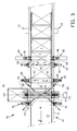
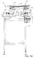
- the checking station 70 illustrated in figures 3, 5A and 5B (not illustrated in figure 2) comprises third brakes 71, the construction of which can be compared with the first brakes 19 and the second brakes 20.
- the checking station 70 comprises a portal 72 which is not completely illustrated, with an upper girder 74 which is attached to the frame 11 in a manner which has not been further illustrated.
- the upper girder 74 is provided with a drive for a slide 73, which is guided on guide bars 75.
- a frame 76 is suspended from the slide 73, to at bottom end of which a pusher plate 77 is attached.
- the slide 73 is displaceable in the directions M transversely along the conveyor belt 12.
- Figure 3 schematically illustrates the location of a photocell 80 which, transversely to the conveyor belt 12, is directed to a reflector 81 which is located at the other side. It furthermore illustrates a photocell 78, which is directed towards a reflector 79 obliquely along a set-up location.
- cylinders 82 are arranged, with a cylinder casing 82a and a piston rod 82b, at the end of which a plunger 83 is arranged.
- the cylinders 82 are oblique at an angle alpha with respect to the horizontal.
- the photocells 78 and 80 are operatively connected with a checking unit (not illustrated), which activates the cylinders 82 dependent upon the signal of the photocell 78.
- the checking unit furthermore activates the driving of the slide 73 dependent upon the signal of photocell 80.
- the operation of the fold-in member 10 is as follows.
- a folding crate 1 is placed at the beginning of the continuous belt conveyor 12 in unfolded condition, wherein the longitudinal walls 3 will be disposed along the guides 17.
- the folding crate 1 is passed in the direction D along the measuring eyes 40 of the measuring station 13, so that the height of a folding crate 1 is electronically established.
- the first brakes 19 are activated by which the first folding crate 1 with the leading transverse wall 4 runs against the first blocking plates 60.
- the belt conveyor 12 itself will continue to slip under the folding crate 1.
- the unlocking grippers 50 are brought from the start position according to figure 4A in the direction G to the correct engagement height in accordance with the measured height.
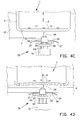
- the metal fingers 37 of the opened pneumatic gripper 33 then arrive in a plane parallel to the plane of the belt conveyor 12 in line with the pull eyes 7 of the folding crate 1. This situation is illustrated in figures 4B and 4C.
Landscapes
- Engineering & Computer Science (AREA)
- Mechanical Engineering (AREA)
- Rigid Containers With Two Or More Constituent Elements (AREA)
- Folding Of Thin Sheet-Like Materials, Special Discharging Devices, And Others (AREA)
- Framework For Endless Conveyors (AREA)
- Pretreatment Of Seeds And Plants (AREA)
- Soy Sauces And Products Related Thereto (AREA)
- Fertilizers (AREA)
Applications Claiming Priority (1)
| Application Number | Priority Date | Filing Date | Title |
|---|---|---|---|
| NL1028457A NL1028457C2 (nl) | 2005-03-03 | 2005-03-03 | Invouwinrichting voor vouwkratten. |
Publications (3)
| Publication Number | Publication Date |
|---|---|
| EP1702850A2 true EP1702850A2 (de) | 2006-09-20 |
| EP1702850A3 EP1702850A3 (de) | 2006-09-27 |
| EP1702850B1 EP1702850B1 (de) | 2008-07-23 |
Family
ID=35134643
Family Applications (1)
| Application Number | Title | Priority Date | Filing Date |
|---|---|---|---|
| EP06075458A Expired - Lifetime EP1702850B1 (de) | 2005-03-03 | 2006-02-28 | Vorrichtung zum Einklappen von Steigen |
Country Status (4)
| Country | Link |
|---|---|
| EP (1) | EP1702850B1 (de) |
| AT (1) | ATE402081T1 (de) |
| DE (1) | DE602006001882D1 (de) |
| NL (1) | NL1028457C2 (de) |
Cited By (3)
| Publication number | Priority date | Publication date | Assignee | Title |
|---|---|---|---|---|
| GB2583932A (en) * | 2019-05-14 | 2020-11-18 | Nissan Motor Mfg Uk Ltd | Device for folding a collapsible crate |
| DE102021114266A1 (de) | 2021-06-02 | 2022-12-08 | Bayerische Motoren Werke Aktiengesellschaft | Vorrichtung und Verfahren zum Zusammenlegen eines über seine verschwenkbaren Seitenwände faltbaren Ladungsträgers |
| CN119389556A (zh) * | 2024-11-05 | 2025-02-07 | 一汽-大众汽车有限公司 | 一种用于料箱的自动折叠装置 |
Family Cites Families (4)
| Publication number | Priority date | Publication date | Assignee | Title |
|---|---|---|---|---|
| GB138248A (en) * | 1919-05-21 | 1920-02-05 | Charles Corben | Improvements in boxes or like containers |
| US4917255A (en) * | 1989-02-24 | 1990-04-17 | J.I.T. Corporation | Collapsible container |
| NL1009800C2 (nl) * | 1998-08-04 | 2000-02-08 | Numafa B V | Inrichting en werkwijze voor het uitvouwen van opvouwbare kratten, en werkwijze voor het ledigen van kratten. |
| IT1310244B1 (it) * | 1999-08-27 | 2002-02-11 | Frutmac S R L | Sistema e macchina per l'apertura automatizzata di cassetteripieghevoli. |
-
2005
- 2005-03-03 NL NL1028457A patent/NL1028457C2/nl not_active IP Right Cessation
-
2006
- 2006-02-28 EP EP06075458A patent/EP1702850B1/de not_active Expired - Lifetime
- 2006-02-28 DE DE602006001882T patent/DE602006001882D1/de not_active Expired - Lifetime
- 2006-02-28 AT AT06075458T patent/ATE402081T1/de not_active IP Right Cessation
Cited By (5)
| Publication number | Priority date | Publication date | Assignee | Title |
|---|---|---|---|---|
| GB2583932A (en) * | 2019-05-14 | 2020-11-18 | Nissan Motor Mfg Uk Ltd | Device for folding a collapsible crate |
| DE102021114266A1 (de) | 2021-06-02 | 2022-12-08 | Bayerische Motoren Werke Aktiengesellschaft | Vorrichtung und Verfahren zum Zusammenlegen eines über seine verschwenkbaren Seitenwände faltbaren Ladungsträgers |
| DE102021114266B4 (de) * | 2021-06-02 | 2025-03-20 | Bayerische Motoren Werke Aktiengesellschaft | Vorrichtung und Verfahren zum Zusammenlegen eines über seine verschwenkbaren Seitenwände faltbaren Ladungsträgers |
| CN119389556A (zh) * | 2024-11-05 | 2025-02-07 | 一汽-大众汽车有限公司 | 一种用于料箱的自动折叠装置 |
| CN119389556B (zh) * | 2024-11-05 | 2025-10-31 | 一汽-大众汽车有限公司 | 一种用于料箱的自动折叠装置 |
Also Published As
| Publication number | Publication date |
|---|---|
| ATE402081T1 (de) | 2008-08-15 |
| NL1028457C2 (nl) | 2006-09-06 |
| DE602006001882D1 (de) | 2008-09-04 |
| EP1702850A3 (de) | 2006-09-27 |
| EP1702850B1 (de) | 2008-07-23 |
Similar Documents
| Publication | Publication Date | Title |
|---|---|---|
| US6976350B2 (en) | Bag presenter for a packaging machine | |
| JP5868117B2 (ja) | シート状材料から成るスタックを反転する装置および方法 | |
| CN104781149B (zh) | 大容量供袋设备 | |
| US20160185065A1 (en) | Method and system for automatically forming packaging boxes | |
| US6322315B1 (en) | Web stacker and separator apparatus and method | |
| US20160159026A1 (en) | Carton feeding system and method and related carton forming and sealing machine | |
| US20070253803A1 (en) | Tray handler and method | |
| JP7675092B2 (ja) | 分離シートをレセプタクルに挿入するための把持システム及び方法 | |
| NL7906864A (nl) | Inrichting voor het opzetten van dozen. | |
| JPH05213513A (ja) | 枚葉紙排紙装置 | |
| US20190061299A1 (en) | Apparatus and method for accurate carton formation | |
| US20080127613A1 (en) | Crate-erecting machine | |
| US11479376B2 (en) | Method for cushioning objects in a container, and device for cushioning objects in a container | |
| US20130164111A1 (en) | Stacking device | |
| EP1702850B1 (de) | Vorrichtung zum Einklappen von Steigen | |
| JP2019521052A (ja) | レジスタ、加工機、及び板状要素の配置方法 | |
| CN114007965A (zh) | 用于处置和/或搬运成至少一排运动的成件货物的设备和方法 | |
| US10960634B2 (en) | Device for opening an end region of a tubular bag body | |
| NL8102118A (nl) | Zakvulinrichting voor verpakkingsmachine. | |
| EP1637455B1 (de) | Vorrichtung zum Aufklappen von Kasten | |
| US5689931A (en) | Case erector with A-B detection | |
| CA2677446A1 (en) | Apparatus for and method of packaging stackable objects, in particular printed products | |
| US20030040413A1 (en) | Case erector | |
| NL1032347C2 (nl) | Invouwinrichting voor vouwkratten. | |
| JP7636783B2 (ja) | 袋供給装置における袋搬送機構 |
Legal Events
| Date | Code | Title | Description |
|---|---|---|---|
| PUAI | Public reference made under article 153(3) epc to a published international application that has entered the european phase |
Free format text: ORIGINAL CODE: 0009012 |
|
| PUAL | Search report despatched |
Free format text: ORIGINAL CODE: 0009013 |
|
| AK | Designated contracting states |
Kind code of ref document: A2 Designated state(s): AT BE BG CH CY CZ DE DK EE ES FI FR GB GR HU IE IS IT LI LT LU LV MC NL PL PT RO SE SI SK TR |
|
| AX | Request for extension of the european patent |
Extension state: AL BA HR MK YU |
|
| AK | Designated contracting states |
Kind code of ref document: A3 Designated state(s): AT BE BG CH CY CZ DE DK EE ES FI FR GB GR HU IE IS IT LI LT LU LV MC NL PL PT RO SE SI SK TR |
|
| AX | Request for extension of the european patent |
Extension state: AL BA HR MK YU |
|
| 17P | Request for examination filed |
Effective date: 20070301 |
|
| 17Q | First examination report despatched |
Effective date: 20070412 |
|
| AKX | Designation fees paid |
Designated state(s): AT BE BG CH CY CZ DE DK EE ES FI FR GB GR HU IE IS IT LI LT LU LV MC NL PL PT RO SE SI SK TR |
|
| GRAP | Despatch of communication of intention to grant a patent |
Free format text: ORIGINAL CODE: EPIDOSNIGR1 |
|
| GRAS | Grant fee paid |
Free format text: ORIGINAL CODE: EPIDOSNIGR3 |
|
| GRAA | (expected) grant |
Free format text: ORIGINAL CODE: 0009210 |
|
| AK | Designated contracting states |
Kind code of ref document: B1 Designated state(s): AT BE BG CH CY CZ DE DK EE ES FI FR GB GR HU IE IS IT LI LT LU LV MC NL PL PT RO SE SI SK TR |
|
| REG | Reference to a national code |
Ref country code: GB Ref legal event code: FG4D |
|
| REG | Reference to a national code |
Ref country code: CH Ref legal event code: EP |
|
| REG | Reference to a national code |
Ref country code: IE Ref legal event code: FG4D |
|
| REF | Corresponds to: |
Ref document number: 602006001882 Country of ref document: DE Date of ref document: 20080904 Kind code of ref document: P |
|
| PG25 | Lapsed in a contracting state [announced via postgrant information from national office to epo] |
Ref country code: LT Free format text: LAPSE BECAUSE OF FAILURE TO SUBMIT A TRANSLATION OF THE DESCRIPTION OR TO PAY THE FEE WITHIN THE PRESCRIBED TIME-LIMIT Effective date: 20080723 Ref country code: IS Free format text: LAPSE BECAUSE OF FAILURE TO SUBMIT A TRANSLATION OF THE DESCRIPTION OR TO PAY THE FEE WITHIN THE PRESCRIBED TIME-LIMIT Effective date: 20081123 |
|
| PG25 | Lapsed in a contracting state [announced via postgrant information from national office to epo] |
Ref country code: BG Free format text: LAPSE BECAUSE OF FAILURE TO SUBMIT A TRANSLATION OF THE DESCRIPTION OR TO PAY THE FEE WITHIN THE PRESCRIBED TIME-LIMIT Effective date: 20081023 Ref country code: FI Free format text: LAPSE BECAUSE OF FAILURE TO SUBMIT A TRANSLATION OF THE DESCRIPTION OR TO PAY THE FEE WITHIN THE PRESCRIBED TIME-LIMIT Effective date: 20080723 Ref country code: ES Free format text: LAPSE BECAUSE OF FAILURE TO SUBMIT A TRANSLATION OF THE DESCRIPTION OR TO PAY THE FEE WITHIN THE PRESCRIBED TIME-LIMIT Effective date: 20081103 Ref country code: AT Free format text: LAPSE BECAUSE OF FAILURE TO SUBMIT A TRANSLATION OF THE DESCRIPTION OR TO PAY THE FEE WITHIN THE PRESCRIBED TIME-LIMIT Effective date: 20080723 Ref country code: LV Free format text: LAPSE BECAUSE OF FAILURE TO SUBMIT A TRANSLATION OF THE DESCRIPTION OR TO PAY THE FEE WITHIN THE PRESCRIBED TIME-LIMIT Effective date: 20080723 Ref country code: SI Free format text: LAPSE BECAUSE OF FAILURE TO SUBMIT A TRANSLATION OF THE DESCRIPTION OR TO PAY THE FEE WITHIN THE PRESCRIBED TIME-LIMIT Effective date: 20080723 Ref country code: PT Free format text: LAPSE BECAUSE OF FAILURE TO SUBMIT A TRANSLATION OF THE DESCRIPTION OR TO PAY THE FEE WITHIN THE PRESCRIBED TIME-LIMIT Effective date: 20081223 |
|
| PG25 | Lapsed in a contracting state [announced via postgrant information from national office to epo] |
Ref country code: DK Free format text: LAPSE BECAUSE OF FAILURE TO SUBMIT A TRANSLATION OF THE DESCRIPTION OR TO PAY THE FEE WITHIN THE PRESCRIBED TIME-LIMIT Effective date: 20080723 Ref country code: EE Free format text: LAPSE BECAUSE OF FAILURE TO SUBMIT A TRANSLATION OF THE DESCRIPTION OR TO PAY THE FEE WITHIN THE PRESCRIBED TIME-LIMIT Effective date: 20080723 |
|
| PG25 | Lapsed in a contracting state [announced via postgrant information from national office to epo] |
Ref country code: CZ Free format text: LAPSE BECAUSE OF FAILURE TO SUBMIT A TRANSLATION OF THE DESCRIPTION OR TO PAY THE FEE WITHIN THE PRESCRIBED TIME-LIMIT Effective date: 20080723 Ref country code: SK Free format text: LAPSE BECAUSE OF FAILURE TO SUBMIT A TRANSLATION OF THE DESCRIPTION OR TO PAY THE FEE WITHIN THE PRESCRIBED TIME-LIMIT Effective date: 20080723 Ref country code: RO Free format text: LAPSE BECAUSE OF FAILURE TO SUBMIT A TRANSLATION OF THE DESCRIPTION OR TO PAY THE FEE WITHIN THE PRESCRIBED TIME-LIMIT Effective date: 20080723 |
|
| PLBE | No opposition filed within time limit |
Free format text: ORIGINAL CODE: 0009261 |
|
| STAA | Information on the status of an ep patent application or granted ep patent |
Free format text: STATUS: NO OPPOSITION FILED WITHIN TIME LIMIT |
|
| 26N | No opposition filed |
Effective date: 20090424 |
|
| PG25 | Lapsed in a contracting state [announced via postgrant information from national office to epo] |
Ref country code: IT Free format text: LAPSE BECAUSE OF FAILURE TO SUBMIT A TRANSLATION OF THE DESCRIPTION OR TO PAY THE FEE WITHIN THE PRESCRIBED TIME-LIMIT Effective date: 20080723 |
|
| NLS | Nl: assignments of ep-patents |
Owner name: NUMAFA HOLDING B.V. Effective date: 20090714 Owner name: POLYLOGISTICS HOLDING B.V. Effective date: 20090714 |
|
| PG25 | Lapsed in a contracting state [announced via postgrant information from national office to epo] |
Ref country code: MC Free format text: LAPSE BECAUSE OF NON-PAYMENT OF DUE FEES Effective date: 20090228 |
|
| REG | Reference to a national code |
Ref country code: FR Ref legal event code: ST Effective date: 20091030 |
|
| PG25 | Lapsed in a contracting state [announced via postgrant information from national office to epo] |
Ref country code: IE Free format text: LAPSE BECAUSE OF NON-PAYMENT OF DUE FEES Effective date: 20090228 Ref country code: SE Free format text: LAPSE BECAUSE OF FAILURE TO SUBMIT A TRANSLATION OF THE DESCRIPTION OR TO PAY THE FEE WITHIN THE PRESCRIBED TIME-LIMIT Effective date: 20081023 |
|
| PG25 | Lapsed in a contracting state [announced via postgrant information from national office to epo] |
Ref country code: FR Free format text: LAPSE BECAUSE OF NON-PAYMENT OF DUE FEES Effective date: 20090302 |
|
| PG25 | Lapsed in a contracting state [announced via postgrant information from national office to epo] |
Ref country code: PL Free format text: LAPSE BECAUSE OF FAILURE TO SUBMIT A TRANSLATION OF THE DESCRIPTION OR TO PAY THE FEE WITHIN THE PRESCRIBED TIME-LIMIT Effective date: 20080723 |
|
| REG | Reference to a national code |
Ref country code: CH Ref legal event code: PL |
|
| GBPC | Gb: european patent ceased through non-payment of renewal fee |
Effective date: 20100228 |
|
| PG25 | Lapsed in a contracting state [announced via postgrant information from national office to epo] |
Ref country code: GR Free format text: LAPSE BECAUSE OF FAILURE TO SUBMIT A TRANSLATION OF THE DESCRIPTION OR TO PAY THE FEE WITHIN THE PRESCRIBED TIME-LIMIT Effective date: 20081024 Ref country code: LI Free format text: LAPSE BECAUSE OF NON-PAYMENT OF DUE FEES Effective date: 20100228 Ref country code: CH Free format text: LAPSE BECAUSE OF NON-PAYMENT OF DUE FEES Effective date: 20100228 |
|
| PG25 | Lapsed in a contracting state [announced via postgrant information from national office to epo] |
Ref country code: GB Free format text: LAPSE BECAUSE OF NON-PAYMENT OF DUE FEES Effective date: 20100228 |
|
| PG25 | Lapsed in a contracting state [announced via postgrant information from national office to epo] |
Ref country code: LU Free format text: LAPSE BECAUSE OF NON-PAYMENT OF DUE FEES Effective date: 20090228 |
|
| PGFP | Annual fee paid to national office [announced via postgrant information from national office to epo] |
Ref country code: DE Payment date: 20110210 Year of fee payment: 6 Ref country code: NL Payment date: 20110225 Year of fee payment: 6 |
|
| PG25 | Lapsed in a contracting state [announced via postgrant information from national office to epo] |
Ref country code: HU Free format text: LAPSE BECAUSE OF FAILURE TO SUBMIT A TRANSLATION OF THE DESCRIPTION OR TO PAY THE FEE WITHIN THE PRESCRIBED TIME-LIMIT Effective date: 20090124 |
|
| PGFP | Annual fee paid to national office [announced via postgrant information from national office to epo] |
Ref country code: BE Payment date: 20110210 Year of fee payment: 6 |
|
| PG25 | Lapsed in a contracting state [announced via postgrant information from national office to epo] |
Ref country code: TR Free format text: LAPSE BECAUSE OF FAILURE TO SUBMIT A TRANSLATION OF THE DESCRIPTION OR TO PAY THE FEE WITHIN THE PRESCRIBED TIME-LIMIT Effective date: 20080723 |
|
| PG25 | Lapsed in a contracting state [announced via postgrant information from national office to epo] |
Ref country code: CY Free format text: LAPSE BECAUSE OF FAILURE TO SUBMIT A TRANSLATION OF THE DESCRIPTION OR TO PAY THE FEE WITHIN THE PRESCRIBED TIME-LIMIT Effective date: 20080723 |
|
| BERE | Be: lapsed |
Owner name: NUMAFA CLEANING AND AUTOMATION B.V. Effective date: 20120228 |
|
| REG | Reference to a national code |
Ref country code: NL Ref legal event code: V1 Effective date: 20120901 |
|
| BECH | Be: change of holder |
Owner name: NUMAFA GROUP B.V. Effective date: 20121119 |
|
| REG | Reference to a national code |
Ref country code: DE Ref legal event code: R119 Ref document number: 602006001882 Country of ref document: DE Effective date: 20120901 |
|
| PG25 | Lapsed in a contracting state [announced via postgrant information from national office to epo] |
Ref country code: BE Free format text: LAPSE BECAUSE OF NON-PAYMENT OF DUE FEES Effective date: 20120228 |
|
| PG25 | Lapsed in a contracting state [announced via postgrant information from national office to epo] |
Ref country code: NL Free format text: LAPSE BECAUSE OF NON-PAYMENT OF DUE FEES Effective date: 20120901 |
|
| PG25 | Lapsed in a contracting state [announced via postgrant information from national office to epo] |
Ref country code: DE Free format text: LAPSE BECAUSE OF NON-PAYMENT OF DUE FEES Effective date: 20120901 |