EP1702855B1 - Contenant à poignée deplaçable - Google Patents
Contenant à poignée deplaçable Download PDFInfo
- Publication number
- EP1702855B1 EP1702855B1 EP06388020A EP06388020A EP1702855B1 EP 1702855 B1 EP1702855 B1 EP 1702855B1 EP 06388020 A EP06388020 A EP 06388020A EP 06388020 A EP06388020 A EP 06388020A EP 1702855 B1 EP1702855 B1 EP 1702855B1
- Authority
- EP
- European Patent Office
- Prior art keywords
- container
- handle
- handles
- slots
- container body
- Prior art date
- Legal status (The legal status is an assumption and is not a legal conclusion. Google has not performed a legal analysis and makes no representation as to the accuracy of the status listed.)
- Expired - Lifetime
Links
Images


Classifications
-
- B—PERFORMING OPERATIONS; TRANSPORTING
- B65—CONVEYING; PACKING; STORING; HANDLING THIN OR FILAMENTARY MATERIAL
- B65D—CONTAINERS FOR STORAGE OR TRANSPORT OF ARTICLES OR MATERIALS, e.g. BAGS, BARRELS, BOTTLES, BOXES, CANS, CARTONS, CRATES, DRUMS, JARS, TANKS, HOPPERS, FORWARDING CONTAINERS; ACCESSORIES, CLOSURES, OR FITTINGS THEREFOR; PACKAGING ELEMENTS; PACKAGES
- B65D25/00—Details of other kinds or types of rigid or semi-rigid containers
- B65D25/28—Handles
- B65D25/32—Bail handles, i.e. pivoted rigid handles of generally semi-circular shape with pivot points on two opposed sides or wall parts of the conainter
Definitions
- the current invention relates to a container with a container body, a lid, and at least one handle where the ends of the at least one handle are pivotably connected to opposite sides of said container body.
- Many containers of this type have a single pivotable handle made from a bent wire, connected to opposite sides of the container and at the container's centre line.
- a common example of this type of container is a can of paint.
- the two ends of a bent wire handle are pivotably attached to the sides of the body of the paint can, close to its top edge.
- the handle is pivoted up for the user to hold on to.
- the handle pivots down and rests on the side the paint can. This allows easy access to the contents of the paint can.
- US 2056827 describes a container with a pivotable handle displaceable between a first and a second position.
- a first disadvantage is that when the handle(s) is pivoted down along the side of the container, the handle(s) partially covers the labelling on the side of the container. This can prevent the user from recognising the contents of the container.
- Another disadvantage is that when the handle is pivoted down along the side of the container, it is difficult for the user to access the handle. If the user wishes to transport the container, the user must first identify on which side of the container the handle is, and then reach down along the side of the container and pivot the handle up into its carrying position.
- the user must first recognize that the container has two handles and then reach down along each side of the container to gather the handles and then pivot them up into their carrying positions. If the user fails to see the second handle and lifts the container by one handle only, the container will tip over instead of being lifted.
- a second aspect is to provide a container as mentioned in the introductory paragraph where the location of the handle(s) is easily recognizable and accessible for correct use while still allowing the user easy access to the contents of the container.
- a third aspect of the current invention is to provide a container as mentioned in the introductory paragraph where the handle(s) does not cover the labelling on the side of the container.
- a fourth aspect of the current invention is to provide a container as mentioned in the introductory paragraph where the container is stackable.
- the handle rests on the edge of the container body or the edge of the lid. In this way, the handle is very visible as well as being easily accessible. Since the handle rests on the edge of the container, the container is still stackable.
- the handle can pivot past the edge of the lid and past the edge of the container allowing it to rest along the side of the container as is known in the state of the art. In this way, the user can easily open the container and gain access to the contents of the container.
- the at least one end of each of the two handles can be connected to said container body via at least one key and slot arrangement.
- the slot is formed in the container body and the at least one end of the at least one handle is formed with a key which is arranged in the slot.
- This embodiment, where the slot is formed in the container, is advantageous since the handle can be made quite simple. It is especially useful in the case where the handle is made from a bent metal wire, as is frequently the case in the prior art.
- the slot is mainly vertically arranged.
- the vertical vector component of the slot's direction is greater than the horizontal vector component of the slot's direction. In this way, gravity ensures that the handle will tend to fall down in the slot and assume the same position each time the handle is released.
- the slot can furthermore be placed at an angle to a vertical centre line of the container body. This increases the effect of displacing the ends of the handle, since the handles when moving in the slot, with move both in a direction along the vertical centre line of the container body as well as a direction perpendicular to the vertical centre line of the container body.
- the angle of the slot could be within the range of 80° to 0°.
- the angle is between 60° and 10°, most preferably, the angle is between 50° and 20°.
- the steeper the angle the easier it is for the handle to fall into its lower position when the handle is released.
- the lower the angle the more the handle will be displaced outwardly when the handle is lifted.
- the choice of the angle can therefore be determined by the above mentioned considerations.
- spring biasing means could be arranged in the slot, in order to bias the end of the handle into one of its positions. This gives a very deterministic action of the handle since the handle will return to the biased position as soon as the user releases the handle.
- the container comprises two handles.
- the ends of the handles are connected to the container body via slots formed in the container body and the slots can be placed in the container body offset from the centre line of the container body.
- the slots can be angled with respect to the centre line of the container body in such a way that the top portions of the slots are further from the centre line of the container than the bottom portions of the slots. In this way, moving the handle from the first position to the second position effectively lengthens the handle more than if the slot were purely vertical.
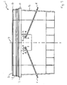
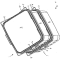
- the containers 1 shown in figures 1-4 comprise a container body 2, a lid 3, and two handles 4.
- the container body 2 and the lid 3 in this case are plastic injection moulded.
- the handles 4 in this embodiment are bent metal wires, but they could just as well also be plastic injection moulded or made from some other material.
- two handles are used to give more stability to the container when being carried. Due to the fact that the two handles are attached to the container at a distance from each other, the container is less likely to tip about the handle attachment point. This is important when the container has a relatively high centre of gravity.
- the ends 5 of the handles 4 are arranged in slots 6.
- the slots 6 are formed in the sides of the container.
- the ends 5 of the handles 4 are prevented from falling out of the slots 6, in that the ends 5 of the handles 4 are slightly larger than the width of the slots 6.
- the ends 5 of the handles 5 are inserted in the slots 6 in the manner which is commonly known from containers of the state of the art.
- the ends 5 of the handles 4 are furthermore arranged such that they are permitted to slide in the slot 6.
- the slots are arranged such that they are placed at an angle a to the centre line 7 of the container.
- the bottom portion 8 of the slot 6 is closer to the centre line 7 than the top portion 9 of the slot 6.
- the slot is a linear slot.
- a slot which is not linear could also be imagined.
- a slot which has a notch could be imagined. The notch could lock the ends of the handle in a certain position, requiring the user to perform a certain action, before the ends of the handle could be put into a different position.
- the effective length of the handles 4 can be increased or decreased.
- the handle 4 when the ends of the handles are in the top part 9 of the slot 6, the handle 4 is effectively longer than when the ends 5 of the handles 4 are in the bottom part 8 of the slot 6. In this way, when the ends 5 of the handles 4 are in the bottom part 8 of the slot 6, the handle 4 is not long enough to go past the edge 10 of the lid 3. The handle 4 therefore rests on the edge 10 of the lid 3. This position is shown in figure 1 . When the handle 4 is in this first position, the handle is easily visible and accessible to the user.
- the handle 4 When the ends 5 of the handle 4 are moved to the top part 9 of the slot 6, the handle 4 is effectively lengthened. In this way, the handle 4 is long enough to pivot past the edge 10 of the lid 3 and the edge 11 of the container 1. This is shown in figure 2 . The handle 4 can therefore be pivoted past the edge 10 of the lid 3 and past the edge 11 of the container 1, thereby allowing the handle 4 to pivot down and rest against the side of the container body 2. This third position is shown in figure 3 . When the handle 4 is in this third position, the user has unobstructed access to the lid 3 of the container 1. The user can therefore easily remove the lid 3 of the container 1 and get access to the contents of the container 1.
- the slots 6 are arranged in a mainly vertical manner in order to provide a deterministic manner of operation.
- the ends of the handles will always go to the top part of the slot.
- the ends of the handles will fall down to the bottom part of the slot.
- the slots 6 are angled at an angle of approximately 30° with respect to the centre line 7 of the container 1. Due to the angle the effect of displacing the ends 5 of the handles 4 is increased. This is due to the fact that when the ends 5 of the handles 4 are in the top part of the slot 6, the handles are displaced both upwardly and outwardly and the effective length of the handles is therefore increased more than if the slots had been purely vertical. By increasing the angle, the length of the handle will be further increased, however if the angle is increased too much, then the ends of the handle will not fall into position in the bottom of the slot as easily when the handle is released.
- the above embodiment has two handles.
- a container with a single handle would also be possible.
- the container could furthermore be equipped with a mechanism, such as a tab, which ensures that the handle always pivots to the same side.
- spring biasing means could be arranged in the slots, in order to bias the handle into its first position. The user would then need to apply a force to the handle to counteract the spring force when it is desired to displace the handle from its first position to its second position.
- the slots could be arranged angled with respect to the centre line of the container in such a way, that the top portions of the slots were arranged closer to the centre line of the container than the bottom portions of the slots. In this way, the ends of the handle would always be in the top portion of the slots, unless the user deliberately forced the handle into its second position. This would prevent the handle from displacing each time the user picked up the container.
- the container could be arranged in the manner that only one end of the handle was displaceable. In this way, a lower cost container would be provided, since the displaceable mechanism would only need to be located on one side of the container.
- the handle itself was extendible. This could for example be implemented in that the handle was made from two independent parts which were displaceable with respect to each other. This could for example be a sort of telescoping mechanism.
Landscapes
- Engineering & Computer Science (AREA)
- Mechanical Engineering (AREA)
- Details Of Rigid Or Semi-Rigid Containers (AREA)
- Thermally Insulated Containers For Foods (AREA)
- Purses, Travelling Bags, Baskets, Or Suitcases (AREA)
Claims (5)
- Contenant (1) comprenant:- un corps-contenant (2);- un couvercle (3);- deux poignées (4)- dans lequel les extrémités (5) de chacune des deux poignées (4) sont accouplées de manière pivotante aux cotés opposés dudit corps-contenant (2) ;- dans lequel l'une au moins des extrémités de chacune des deux poignées (4) est déplaçable entre une première position (8) et une deuxième position (9) de manière à ce que, quand l'au moins une extrémité déplaçable (5) d'une poignée (4) est dans sa première position (8), ladite poignée (4) est capable de prendre appui sur le bord dudit contenant (1) ou le bord (10) dudit couvercle (3) ; et que, quand l'au moins une extrémité déplaçable (5) de ladite poignée (4) est dans sa deuxième position (9), ladite poignée peut se faire pivoter au delà du bord (10) du couvercle (3) et au-delà du bord (11) dudit contenant (1), de sorte que ladite poignée prenne appui le long du coté du contenant (1) ;- dans lequel l'au moins une extrémité déplaçable (5) de chacune des deux poignées (4) est accouplée audit corps-contenant (2) par voie d'au moins un arrangement arête et rainure dont les rainures (6) sont aménagées dans le corps-contenant (2) et dont l'une au moins des extrémités déplaçables (5) de chacune des deux poignées (4) forme une rainure (5) qui est aménagé dans un des arêtes (6) ; et- dans lequel les rainures (6) sont aménagées de manière principalement verticale.
- Contenant (1) selon la revendication 1, caractérisé en ce que les rainures (6) sont aménagées à un angle (α) par rapport à un axe central (7) dudit corps-contenant (2), ledit angle (α) allant de 80° à 0°, étant préférentiellement entre 60° et 10°, et plus préférentiellement entre 50° et 20°.
- Contenant selon l'une quelconque des revendications 1 à 2, caractérisé en ce qu'un moyen de tension par ressort est aménagé dans les rainures, lesdits moyens de tension par ressort tensionnant l'extrémité de la poignée dans l'une de ses positions.
- Contenant (1) selon l'une quelconque des revendications 1 à 3, caractérisé en ce que les extrémités (5) des poignées (4) sont accouplées au corps-contenant (2) par voie des rainures (6) configurées dans le corps-contenant (2), et en ce que les rainures (6) sont aménagées dans le corps-contenant (2) de manière déplacée par rapport à l'axe central (7) dudit corps-contenant (2).
- Contenant (1) selon l'une quelconque des revendications 1 à 4, caractérisé en ce que les rainures (6) sont positionnées à un angle par rapport à l'axe central (7) du corps-contenant (2) de manière à ce que les portions supérieures (9) desdites rainures (6) sont plus éloignées de l'axe central (7) du corps-contenant (2) que les parties inférieures (8) desdites rainures (6).
Priority Applications (3)
| Application Number | Priority Date | Filing Date | Title |
|---|---|---|---|
| SI200631035T SI1702855T1 (sl) | 2005-03-18 | 2006-03-17 | Vsebnik s premičnim ročajem |
| PL06388020T PL1702855T3 (pl) | 2005-03-18 | 2006-03-17 | Pojemnik z przesuwnym uchwytem |
| CY20111100547T CY1111766T1 (el) | 2005-03-18 | 2011-06-08 | Δοχειο με μετατοπισιμη λαβη |
Applications Claiming Priority (1)
| Application Number | Priority Date | Filing Date | Title |
|---|---|---|---|
| DKPA200500398 | 2005-03-18 |
Publications (4)
| Publication Number | Publication Date |
|---|---|
| EP1702855A2 EP1702855A2 (fr) | 2006-09-20 |
| EP1702855A3 EP1702855A3 (fr) | 2009-04-08 |
| EP1702855B1 true EP1702855B1 (fr) | 2011-03-09 |
| EP1702855B8 EP1702855B8 (fr) | 2011-04-13 |
Family
ID=36603532
Family Applications (1)
| Application Number | Title | Priority Date | Filing Date |
|---|---|---|---|
| EP06388020A Expired - Lifetime EP1702855B8 (fr) | 2005-03-18 | 2006-03-17 | Contenant à poignée deplaçable |
Country Status (9)
| Country | Link |
|---|---|
| EP (1) | EP1702855B8 (fr) |
| AT (1) | ATE501050T1 (fr) |
| CY (1) | CY1111766T1 (fr) |
| DE (1) | DE602006020517D1 (fr) |
| DK (1) | DK1702855T3 (fr) |
| ES (1) | ES2362892T3 (fr) |
| PL (1) | PL1702855T3 (fr) |
| PT (1) | PT1702855E (fr) |
| SI (1) | SI1702855T1 (fr) |
Families Citing this family (4)
| Publication number | Priority date | Publication date | Assignee | Title |
|---|---|---|---|---|
| WO2005120864A2 (fr) | 2004-06-08 | 2005-12-22 | Imperial Chemical Industries Plc | Combinaison de revetement |
| DE102017108032A1 (de) | 2017-04-13 | 2018-10-18 | Saier Verpackungstechnik Gmbh & Co. Kg | Behälter mit arretierbarem Tragbügel |
| JP7278108B2 (ja) * | 2019-03-06 | 2023-05-19 | アイシン軽金属株式会社 | スロープの取手取付構造 |
| CN113525238A (zh) * | 2020-04-17 | 2021-10-22 | 爱信轻金属株式会社 | 斜坡装置的把手安装结构 |
Family Cites Families (6)
| Publication number | Priority date | Publication date | Assignee | Title |
|---|---|---|---|---|
| US1328672A (en) * | 1917-03-29 | 1920-01-20 | Hirsohn Isaac | Bucket-closure |
| US2056827A (en) * | 1934-07-09 | 1936-10-06 | Continental Oil Co | Container |
| CH300228A (de) * | 1952-04-23 | 1954-07-15 | Mitschjeta Max | Transportbehälter mit zwei Traggriffen. |
| AU5793880A (en) * | 1979-05-14 | 1980-11-20 | Continental Group Inc., The | Paint can handles |
| GB2262929A (en) * | 1991-12-30 | 1993-07-07 | Lin Pac Mouldings | Container assembly |
| FR2715375B1 (fr) * | 1994-01-25 | 1996-04-05 | Safet Embamet | Récipient métallique à anse en matière plastique. |
-
2006
- 2006-03-17 AT AT06388020T patent/ATE501050T1/de active
- 2006-03-17 SI SI200631035T patent/SI1702855T1/sl unknown
- 2006-03-17 ES ES06388020T patent/ES2362892T3/es not_active Expired - Lifetime
- 2006-03-17 DK DK06388020.7T patent/DK1702855T3/da active
- 2006-03-17 DE DE602006020517T patent/DE602006020517D1/de not_active Expired - Lifetime
- 2006-03-17 PL PL06388020T patent/PL1702855T3/pl unknown
- 2006-03-17 PT PT06388020T patent/PT1702855E/pt unknown
- 2006-03-17 EP EP06388020A patent/EP1702855B8/fr not_active Expired - Lifetime
-
2011
- 2011-06-08 CY CY20111100547T patent/CY1111766T1/el unknown
Also Published As
| Publication number | Publication date |
|---|---|
| DK1702855T3 (da) | 2011-06-14 |
| EP1702855A2 (fr) | 2006-09-20 |
| EP1702855A3 (fr) | 2009-04-08 |
| PT1702855E (pt) | 2011-06-17 |
| ES2362892T3 (es) | 2011-07-14 |
| CY1111766T1 (el) | 2015-10-07 |
| SI1702855T1 (sl) | 2011-07-29 |
| EP1702855B8 (fr) | 2011-04-13 |
| ATE501050T1 (de) | 2011-03-15 |
| DE602006020517D1 (de) | 2011-04-21 |
| PL1702855T3 (pl) | 2011-11-30 |
Similar Documents
| Publication | Publication Date | Title |
|---|---|---|
| US5772033A (en) | Container | |
| US7780036B2 (en) | Handbasket | |
| USD427769S (en) | Container | |
| US5071033A (en) | Tablet dispenser | |
| US5626244A (en) | Bat rack for chain link fence | |
| US6889838B2 (en) | Tool Box | |
| US6672471B2 (en) | Tablet box construction | |
| US7673769B2 (en) | Storage bin with moveable lid and attached scoop | |
| US20100200446A1 (en) | Tool cases with easy removal of stored items | |
| KR980009049A (ko) | 저장 용기 | |
| EP1702855B1 (fr) | Contenant à poignée deplaçable | |
| EP0362314A4 (fr) | Piege a animaux. | |
| EP1192089A1 (fr) | Panier avec logement faconne dans sa structure | |
| US5148975A (en) | Trash receptacle tray support and method for emptying tray | |
| US5662220A (en) | Case | |
| US20060207994A1 (en) | Container with displaceable handle | |
| US5201428A (en) | Napkin holder | |
| NL8800929A (nl) | Houder of vat. | |
| US7866541B2 (en) | Fish cooler with counting means | |
| US20060102629A1 (en) | Method for protecting beverage can from insects | |
| KR100654035B1 (ko) | 손가방과 같은 휴대용 용기에서의 뚜껑잠금구조 | |
| EP1186542A1 (fr) | Récipient avec couvercle réglable en hauteur | |
| EP0155777A1 (fr) | Anse et article muni d'une telle anse | |
| KR940000229Y1 (ko) | 서류정리케이스 | |
| KR101935535B1 (ko) | 복수의 걸림턱부를 포함하는 대형우편상자 |
Legal Events
| Date | Code | Title | Description |
|---|---|---|---|
| PUAI | Public reference made under article 153(3) epc to a published international application that has entered the european phase |
Free format text: ORIGINAL CODE: 0009012 |
|
| AK | Designated contracting states |
Kind code of ref document: A2 Designated state(s): AT BE BG CH CY CZ DE DK EE ES FI FR GB GR HU IE IS IT LI LT LU LV MC NL PL PT RO SE SI SK TR |
|
| AX | Request for extension of the european patent |
Extension state: AL BA HR MK YU |
|
| PUAL | Search report despatched |
Free format text: ORIGINAL CODE: 0009013 |
|
| AK | Designated contracting states |
Kind code of ref document: A3 Designated state(s): AT BE BG CH CY CZ DE DK EE ES FI FR GB GR HU IE IS IT LI LT LU LV MC NL PL PT RO SE SI SK TR |
|
| AX | Request for extension of the european patent |
Extension state: AL BA HR MK YU |
|
| 17P | Request for examination filed |
Effective date: 20091006 |
|
| AKX | Designation fees paid |
Designated state(s): AT BE BG CH CY CZ DE DK EE ES FI FR GB GR HU IE IS IT LI LT LU LV MC NL PL PT RO SE SI SK TR |
|
| AXX | Extension fees paid |
Extension state: AL Payment date: 20091006 Extension state: MK Payment date: 20091006 Extension state: YU Payment date: 20091006 Extension state: HR Payment date: 20091006 Extension state: BA Payment date: 20091006 |
|
| GRAP | Despatch of communication of intention to grant a patent |
Free format text: ORIGINAL CODE: EPIDOSNIGR1 |
|
| GRAS | Grant fee paid |
Free format text: ORIGINAL CODE: EPIDOSNIGR3 |
|
| GRAA | (expected) grant |
Free format text: ORIGINAL CODE: 0009210 |
|
| AK | Designated contracting states |
Kind code of ref document: B1 Designated state(s): AT BE BG CH CY CZ DE DK EE ES FI FR GB GR HU IE IS IT LI LT LU LV MC NL PL PT RO SE SI SK TR |
|
| AX | Request for extension of the european patent |
Extension state: AL BA HR MK YU |
|
| REG | Reference to a national code |
Ref country code: GB Ref legal event code: FG4D |
|
| REG | Reference to a national code |
Ref country code: CH Ref legal event code: EP |
|
| RAP2 | Party data changed (patent owner data changed or rights of a patent transferred) |
Owner name: SUPERFOS A/S |
|
| REG | Reference to a national code |
Ref country code: IE Ref legal event code: FG4D |
|
| REF | Corresponds to: |
Ref document number: 602006020517 Country of ref document: DE Date of ref document: 20110421 Kind code of ref document: P |
|
| REG | Reference to a national code |
Ref country code: DE Ref legal event code: R096 Ref document number: 602006020517 Country of ref document: DE Effective date: 20110421 |
|
| REG | Reference to a national code |
Ref country code: NL Ref legal event code: T3 |
|
| REG | Reference to a national code |
Ref country code: DE Ref legal event code: R081 Ref document number: 602006020517 Country of ref document: DE Owner name: SUPERFOS A/S, DK Free format text: FORMER OWNER: SUPERFOS A/S, VIPPEROD, DK Effective date: 20110308 |
|
| REG | Reference to a national code |
Ref country code: RO Ref legal event code: EPE |
|
| REG | Reference to a national code |
Ref country code: DK Ref legal event code: T3 |
|
| REG | Reference to a national code |
Ref country code: PT Ref legal event code: SC4A Free format text: AVAILABILITY OF NATIONAL TRANSLATION Effective date: 20110608 |
|
| REG | Reference to a national code |
Ref country code: SE Ref legal event code: TRGR |
|
| REG | Reference to a national code |
Ref country code: ES Ref legal event code: FG2A Ref document number: 2362892 Country of ref document: ES Kind code of ref document: T3 Effective date: 20110714 |
|
| PGFP | Annual fee paid to national office [announced via postgrant information from national office to epo] |
Ref country code: MC Payment date: 20110518 Year of fee payment: 7 |
|
| REG | Reference to a national code |
Ref country code: GR Ref legal event code: EP Ref document number: 20110401354 Country of ref document: GR Effective date: 20110714 |
|
| REG | Reference to a national code |
Ref country code: SK Ref legal event code: T3 Ref document number: E 9606 Country of ref document: SK |
|
| REG | Reference to a national code |
Ref country code: HU Ref legal event code: AG4A Ref document number: E011313 Country of ref document: HU |
|
| REG | Reference to a national code |
Ref country code: PL Ref legal event code: T3 |
|
| PLBE | No opposition filed within time limit |
Free format text: ORIGINAL CODE: 0009261 |
|
| STAA | Information on the status of an ep patent application or granted ep patent |
Free format text: STATUS: NO OPPOSITION FILED WITHIN TIME LIMIT |
|
| 26N | No opposition filed |
Effective date: 20111212 |
|
| REG | Reference to a national code |
Ref country code: DE Ref legal event code: R097 Ref document number: 602006020517 Country of ref document: DE Effective date: 20111212 |
|
| PGFP | Annual fee paid to national office [announced via postgrant information from national office to epo] |
Ref country code: CY Payment date: 20150309 Year of fee payment: 10 |
|
| REG | Reference to a national code |
Ref country code: FR Ref legal event code: PLFP Year of fee payment: 11 |
|
| PGFP | Annual fee paid to national office [announced via postgrant information from national office to epo] |
Ref country code: CH Payment date: 20160323 Year of fee payment: 11 Ref country code: SK Payment date: 20160317 Year of fee payment: 11 Ref country code: LT Payment date: 20160218 Year of fee payment: 11 Ref country code: IE Payment date: 20160323 Year of fee payment: 11 Ref country code: TR Payment date: 20160219 Year of fee payment: 11 Ref country code: NL Payment date: 20160321 Year of fee payment: 11 Ref country code: BG Payment date: 20160311 Year of fee payment: 11 Ref country code: LU Payment date: 20160324 Year of fee payment: 11 Ref country code: CZ Payment date: 20160316 Year of fee payment: 11 Ref country code: EE Payment date: 20160311 Year of fee payment: 11 Ref country code: IS Payment date: 20160218 Year of fee payment: 11 |
|
| PGFP | Annual fee paid to national office [announced via postgrant information from national office to epo] |
Ref country code: RO Payment date: 20160222 Year of fee payment: 11 Ref country code: BE Payment date: 20160321 Year of fee payment: 11 Ref country code: PT Payment date: 20160317 Year of fee payment: 11 Ref country code: GR Payment date: 20160311 Year of fee payment: 11 Ref country code: AT Payment date: 20160322 Year of fee payment: 11 Ref country code: HU Payment date: 20160316 Year of fee payment: 11 Ref country code: LV Payment date: 20160310 Year of fee payment: 11 Ref country code: SI Payment date: 20160222 Year of fee payment: 11 Ref country code: FI Payment date: 20160311 Year of fee payment: 11 |
|
| PGFP | Annual fee paid to national office [announced via postgrant information from national office to epo] |
Ref country code: DE Payment date: 20160330 Year of fee payment: 11 |
|
| PG25 | Lapsed in a contracting state [announced via postgrant information from national office to epo] |
Ref country code: CY Free format text: LAPSE BECAUSE OF NON-PAYMENT OF DUE FEES Effective date: 20160317 |
|
| REG | Reference to a national code |
Ref country code: FR Ref legal event code: PLFP Year of fee payment: 12 |
|
| REG | Reference to a national code |
Ref country code: DE Ref legal event code: R119 Ref document number: 602006020517 Country of ref document: DE |
|
| REG | Reference to a national code |
Ref country code: LT Ref legal event code: MM4D Effective date: 20170317 |
|
| REG | Reference to a national code |
Ref country code: EE Ref legal event code: MM4A Ref document number: E005486 Country of ref document: EE Effective date: 20170331 |
|
| PG25 | Lapsed in a contracting state [announced via postgrant information from national office to epo] |
Ref country code: RO Free format text: LAPSE BECAUSE OF NON-PAYMENT OF DUE FEES Effective date: 20170317 Ref country code: FI Free format text: LAPSE BECAUSE OF NON-PAYMENT OF DUE FEES Effective date: 20170317 Ref country code: LT Free format text: LAPSE BECAUSE OF NON-PAYMENT OF DUE FEES Effective date: 20170317 Ref country code: CZ Free format text: LAPSE BECAUSE OF NON-PAYMENT OF DUE FEES Effective date: 20170317 |
|
| REG | Reference to a national code |
Ref country code: CH Ref legal event code: PL |
|
| REG | Reference to a national code |
Ref country code: NL Ref legal event code: MM Effective date: 20170401 |
|
| REG | Reference to a national code |
Ref country code: AT Ref legal event code: MM01 Ref document number: 501050 Country of ref document: AT Kind code of ref document: T Effective date: 20170317 |
|
| PG25 | Lapsed in a contracting state [announced via postgrant information from national office to epo] |
Ref country code: PT Free format text: LAPSE BECAUSE OF NON-PAYMENT OF DUE FEES Effective date: 20170918 Ref country code: LV Free format text: LAPSE BECAUSE OF NON-PAYMENT OF DUE FEES Effective date: 20170317 |
|
| REG | Reference to a national code |
Ref country code: SK Ref legal event code: MM4A Ref document number: E 9606 Country of ref document: SK Effective date: 20170317 |
|
| REG | Reference to a national code |
Ref country code: IE Ref legal event code: MM4A |
|
| PG25 | Lapsed in a contracting state [announced via postgrant information from national office to epo] |
Ref country code: DE Free format text: LAPSE BECAUSE OF NON-PAYMENT OF DUE FEES Effective date: 20171003 Ref country code: HU Free format text: LAPSE BECAUSE OF NON-PAYMENT OF DUE FEES Effective date: 20170318 Ref country code: NL Free format text: LAPSE BECAUSE OF NON-PAYMENT OF DUE FEES Effective date: 20170401 Ref country code: LU Free format text: LAPSE BECAUSE OF NON-PAYMENT OF DUE FEES Effective date: 20170317 Ref country code: EE Free format text: LAPSE BECAUSE OF NON-PAYMENT OF DUE FEES Effective date: 20170331 Ref country code: SK Free format text: LAPSE BECAUSE OF NON-PAYMENT OF DUE FEES Effective date: 20170317 Ref country code: AT Free format text: LAPSE BECAUSE OF NON-PAYMENT OF DUE FEES Effective date: 20170317 |
|
| REG | Reference to a national code |
Ref country code: SI Ref legal event code: KO00 Effective date: 20171208 |
|
| PG25 | Lapsed in a contracting state [announced via postgrant information from national office to epo] |
Ref country code: LI Free format text: LAPSE BECAUSE OF NON-PAYMENT OF DUE FEES Effective date: 20170331 Ref country code: GR Free format text: LAPSE BECAUSE OF NON-PAYMENT OF DUE FEES Effective date: 20171005 Ref country code: IE Free format text: LAPSE BECAUSE OF NON-PAYMENT OF DUE FEES Effective date: 20170317 Ref country code: SI Free format text: LAPSE BECAUSE OF NON-PAYMENT OF DUE FEES Effective date: 20170318 Ref country code: CH Free format text: LAPSE BECAUSE OF NON-PAYMENT OF DUE FEES Effective date: 20170331 Ref country code: IS Free format text: LAPSE BECAUSE OF FAILURE TO SUBMIT A TRANSLATION OF THE DESCRIPTION OR TO PAY THE FEE WITHIN THE PRESCRIBED TIME-LIMIT Effective date: 20171001 |
|
| REG | Reference to a national code |
Ref country code: BE Ref legal event code: MM Effective date: 20170331 |
|
| REG | Reference to a national code |
Ref country code: FR Ref legal event code: PLFP Year of fee payment: 13 |
|
| PG25 | Lapsed in a contracting state [announced via postgrant information from national office to epo] |
Ref country code: BE Free format text: LAPSE BECAUSE OF NON-PAYMENT OF DUE FEES Effective date: 20170331 |
|
| PG25 | Lapsed in a contracting state [announced via postgrant information from national office to epo] |
Ref country code: BG Free format text: LAPSE BECAUSE OF NON-PAYMENT OF DUE FEES Effective date: 20171006 |
|
| PGFP | Annual fee paid to national office [announced via postgrant information from national office to epo] |
Ref country code: GB Payment date: 20200323 Year of fee payment: 15 Ref country code: DK Payment date: 20200324 Year of fee payment: 15 Ref country code: PL Payment date: 20200224 Year of fee payment: 15 Ref country code: SE Payment date: 20200323 Year of fee payment: 15 |
|
| PGFP | Annual fee paid to national office [announced via postgrant information from national office to epo] |
Ref country code: FR Payment date: 20200319 Year of fee payment: 15 |
|
| PGFP | Annual fee paid to national office [announced via postgrant information from national office to epo] |
Ref country code: ES Payment date: 20200522 Year of fee payment: 15 |
|
| PGFP | Annual fee paid to national office [announced via postgrant information from national office to epo] |
Ref country code: IT Payment date: 20200318 Year of fee payment: 15 |
|
| REG | Reference to a national code |
Ref country code: DK Ref legal event code: EBP Effective date: 20210331 |
|
| GBPC | Gb: european patent ceased through non-payment of renewal fee |
Effective date: 20210317 |
|
| PG25 | Lapsed in a contracting state [announced via postgrant information from national office to epo] |
Ref country code: GB Free format text: LAPSE BECAUSE OF NON-PAYMENT OF DUE FEES Effective date: 20210317 Ref country code: FR Free format text: LAPSE BECAUSE OF NON-PAYMENT OF DUE FEES Effective date: 20210331 Ref country code: SE Free format text: LAPSE BECAUSE OF NON-PAYMENT OF DUE FEES Effective date: 20210318 |
|
| PG25 | Lapsed in a contracting state [announced via postgrant information from national office to epo] |
Ref country code: IT Free format text: LAPSE BECAUSE OF NON-PAYMENT OF DUE FEES Effective date: 20210317 Ref country code: DK Free format text: LAPSE BECAUSE OF NON-PAYMENT OF DUE FEES Effective date: 20210331 |
|
| REG | Reference to a national code |
Ref country code: ES Ref legal event code: FD2A Effective date: 20220523 |
|
| PG25 | Lapsed in a contracting state [announced via postgrant information from national office to epo] |
Ref country code: TR Free format text: LAPSE BECAUSE OF NON-PAYMENT OF DUE FEES Effective date: 20170317 |
|
| PG25 | Lapsed in a contracting state [announced via postgrant information from national office to epo] |
Ref country code: ES Free format text: LAPSE BECAUSE OF NON-PAYMENT OF DUE FEES Effective date: 20210318 |
|
| PG25 | Lapsed in a contracting state [announced via postgrant information from national office to epo] |
Ref country code: PL Free format text: LAPSE BECAUSE OF NON-PAYMENT OF DUE FEES Effective date: 20210317 |