EP1702893B1 - Verfahren und Vorrichtung zum Trennen von Glasschmelze - Google Patents
Verfahren und Vorrichtung zum Trennen von Glasschmelze Download PDFInfo
- Publication number
- EP1702893B1 EP1702893B1 EP05005481.6A EP05005481A EP1702893B1 EP 1702893 B1 EP1702893 B1 EP 1702893B1 EP 05005481 A EP05005481 A EP 05005481A EP 1702893 B1 EP1702893 B1 EP 1702893B1
- Authority
- EP
- European Patent Office
- Prior art keywords
- glass material
- cam
- members
- cutting
- cutting blades
- Prior art date
- Legal status (The legal status is an assumption and is not a legal conclusion. Google has not performed a legal analysis and makes no representation as to the accuracy of the status listed.)
- Expired - Lifetime
Links
- 238000005520 cutting process Methods 0.000 title claims description 97
- 239000000463 material Substances 0.000 title claims description 66
- 238000000034 method Methods 0.000 title description 14
- 239000006060 molten glass Substances 0.000 title description 2
- 239000011521 glass Substances 0.000 claims description 83
- 238000009826 distribution Methods 0.000 description 3
- 238000004519 manufacturing process Methods 0.000 description 3
- 241000234295 Musa Species 0.000 description 2
- 235000018290 Musa x paradisiaca Nutrition 0.000 description 2
- 230000006866 deterioration Effects 0.000 description 1
- 238000007496 glass forming Methods 0.000 description 1
- 230000002093 peripheral effect Effects 0.000 description 1
- 235000013580 sausages Nutrition 0.000 description 1
Images

Classifications
-
- C—CHEMISTRY; METALLURGY
- C03—GLASS; MINERAL OR SLAG WOOL
- C03B—MANUFACTURE, SHAPING, OR SUPPLEMENTARY PROCESSES
- C03B7/00—Distributors for the molten glass; Means for taking-off charges of molten glass; Producing the gob, e.g. controlling the gob shape, weight or delivery tact
- C03B7/10—Cutting-off or severing the glass flow with the aid of knives or scissors or non-contacting cutting means, e.g. a gas jet; Construction of the blades used
-
- Y—GENERAL TAGGING OF NEW TECHNOLOGICAL DEVELOPMENTS; GENERAL TAGGING OF CROSS-SECTIONAL TECHNOLOGIES SPANNING OVER SEVERAL SECTIONS OF THE IPC; TECHNICAL SUBJECTS COVERED BY FORMER USPC CROSS-REFERENCE ART COLLECTIONS [XRACs] AND DIGESTS
- Y02—TECHNOLOGIES OR APPLICATIONS FOR MITIGATION OR ADAPTATION AGAINST CLIMATE CHANGE
- Y02P—CLIMATE CHANGE MITIGATION TECHNOLOGIES IN THE PRODUCTION OR PROCESSING OF GOODS
- Y02P40/00—Technologies relating to the processing of minerals
- Y02P40/50—Glass production, e.g. reusing waste heat during processing or shaping
- Y02P40/57—Improving the yield, e-g- reduction of reject rates
Definitions
- This invention relates to a glass material cutting apparatus.
- a glass material melted in a furnace is adjusted in temperature to a value necessary to form a desired glass product, is transferred to and discharged from a glass material reservoir called a spout, is cut into a mass of glass (gob) having a predetermined size, and is supplied to a forming apparatus.
- a cutting apparatus having a cutter blade, is provided beneath an orifice provided in the lower portion of the spout.
- a conventional glass material cutting apparatus used in a glass forming apparatus such as a bottle manufacturing apparatus or the like
- arms provided with left and right cutting blades are opposed to each other and are moved along arc-shaped tracks or linear tracks to come close to or away from one another in order to cut the glass material (see, e.g., Japanese Kohyo No. 10-511633 and, in particular, pages 4 and 5, Figs. 1 and 2 thereof).
- the temperature of the glass material is increased to thereby reduce the viscosity so that the cutting blades can be moved at a high-speed.
- this solution to enhance the productivity the following problems have been raised.
- any type of cutting apparatus in which the cutting blades are opened and closed with respect to a glass material by an arcwise movement or translation, if the temperature is increased to reduce the viscosity of the glass material in order to respond to a need for a high-speed manufacturing, a so-called "banana shaped gob phenomenon" in which a soft glass material having a low viscosity rides on the upper surfaces of the cutting blades and is moved together therewith and is bent in the same direction as the movement of the cutting blades tends to occur when the glass material is cut. If this phenomenon occurs, the glass material tends to be minutely damaged at its lower portion or to have a non-uniform temperature distribution, thus leading to deterioration of the quality of the product.
- a so-called "banana shaped gob phenomenon” in which a soft glass material having a low viscosity rides on the upper surfaces of the cutting blades and is moved together therewith and is bent in the same direction as the movement of the cutting blades tends to occur when the glass material is
- EP 0 546 216 A1 discloses a method and apparatus for cutting molten glass for forming glass products. Cutting blades are moved downwards after cutting the glass material. A circular cutting path is used, wherein the cutting path can also be elliptical or can have other closed loop shapes.
- US 1 362 785 A discloses a method and apparatus for obtaining glass mold charges. In this method and apparatus, cutting blades are moved downwards after cutting the glass material.
- Fig. 1 is a schematic sectional view of an example of a glass material cutting method applicable in invention.
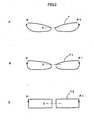
- Fig. 2 shows movement tracks of cutting blades.
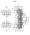
- Fig. 3 is a partially omitted sectional view of an example of a cutting apparatus to perform a method shown in Fig. 1 .
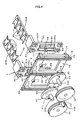
- Fig. 4 is an exploded perspective view of a main portion of a cutting apparatus shown in Fig. 3 .
- a method for a cutting glass material is related to a method for cutting a glass material 20 discharged from a glass material reservoir 10 into a glass gob 21 of a predetermined size by left and right cutting blades 91 and 92 which are moved close to or away from each other in a horizontal direction.
- left and right cutting blades 91 and 92 which are moved close to or away from each other in a horizontal direction.
- numeral 11 designates a glass dissolving furnace which is connected to the glass material reservoir 10; 12 a plunger which moves the glass material out of the glass material reservoir 10; 15 an orifice through which a predetermined amount of glass material is discharged and which is replaceably mounted to the lower portion of the glass material reservoir 10; 16 a guide portion which guides the cut glass gob 21 to a forming die or the like; and 81B and 82B the arm portions on which the left and right cutting blades 91 and 92 are mounted, respectively.
- Fig. 1 in which the tracks of movement of the left and right cutting blades 91 and 92 are indicated at "T”, the left and right cutting blades 91 and 92 are moved forward from respective stand-by positions (retracted positions) P, P1, are moved downward (S1), to cut the glass material 20 as indicated at (C). Thereafter, the left and right cutting blades 91 and 92 are further moved downward, are moved backward (S2), and thereafter, are moved upward to be returned back to the stand-by positions P and P1 (S3).
- the glass material 20 is cut (C).
- the cutting blades 91 and 92 which are moved close to or away from one another in the horizontal direction with respect to the glass material 20 discharged from the orifice 15 of the glass material reservoir 10 are simultaneously brought into contact with the glass material 20 and it is possible to prevent the glass material from riding on the upper surfaces of the cutting blades 91 and 92 and moving together therewith because, as shown in the drawings, the left cutting blades 91 and the right cutting blades 92 are moved forward and downward (S1) to cut the glass material 20 (C), and are thereafter, moved downward and backward (S2).
- Figs. 2A-2C show different examples of the movement tracks of the cutting blades 91, 92.
- Fig. 2A shows the track "T” in the embodiment shown in Fig. 1 .
- the downward movement of the cutting blades from the cutting position (C) occur in the vertical direction.
- the movement tracks of the cutting blades are of rectangular shape consisting of horizontal forward and backward movements and vertical upward and downward movement.
- a glass material cutting apparatus for cutting a glass material 20 discharged from a glass material reservoir 10 into a glass gob of a predetermined size by left and right cutting blades 91, 92 opposed to each other, comprising a horizontal movement mechanism (H) for translating said cutting blades close to or away from each other in a horizontal direction, and an upward and downward movement mechanism (V) for moving said horizontal movement mechanism in an upward and downward direction, said cutting blades 91, 92 being moved in a forward direction from respective stand-by positions P, P1 and in a downward direction (S1) to cut the glass material (C), and thereafter, in a further downward direction (S2) and in a backward direction, and thereafter, in an upward direction to return back to said stand-by positions (S3).
- H horizontal movement mechanism
- V upward and downward movement mechanism
- a glass material cutting apparatus has a single driving portion 52 which drives said horizontal movement mechanism H and said upward and downward movement mechanism V. Therefore, the cutting apparatus becomes effective and efficiently.
- the cutting apparatus which is driven by the single driving portion 52 described in claim 3 has the driving portion 52, left and right operating members 55 and 56, left and right cam member 61 and 62, and an elevator member 70, left and right supporting member 81 and 82, and left and right cutting blades 91 and 92.
- the driving portion 52 has a single drive motor 52A mounted on a base plate 51 which constitutes a stationary portion and a drive gear 53 connected to a rotor shaft 52B of the drive motor 52A.
- a conventional servo motor is preferably used for the drive motor 52A.
- the operating members 55 and 56 are comprised of gears which are engaged with and rotated by the drive gear 53 of the driving portion 52, and are juxtaposed symmetrically with respect to the drive gear 53.
- Numerals 55A and 56A in the drawings designate the rotor shafts of the operating members 55 and 56.
- Numerals 55B and 56B are bearings for the rotor shafts 55A and 56A, which are mounted on the base plate 51.
- the cam members 61 and 62 are made of plates having a cam profile as shown in Fig. 4 and are connected to the rotor shafts 55A and 56A of the operating members 55 and 56, respectively, so as to rotate together with the operating members 55 and 56.
- the cam members 61, 62 are provided with first cam portions 65, 66 and second cam portions 67, 68, respectively.
- the outer peripheral surface portions of the cam members 61, 62 define the first cam portions 65, 66 and a freely rotatable members provided on the surface of the plates of the cam members 61, 62 define the second cam portions 67, 68.
- the second cam portions 67, 68 extend through the openings of the elevator member 70 which will be discuss hereinafter and to a side thereof opposite to the driving portion 52.
- the first cam portions 65, 66 and the second cam portions 67, 68 are arranged so as to engage with corresponding engagement portion which will be discussed below, in order to carry out in a predetermined movement (along the movement tracks mentioned above).
- the elevator member 70 is in the form of a frame and is provided with first engagement portions 71, 72 which are engaged by the first cam portions 65,66 of the left and right cam portions 61, 62, respectively.
- the first engagement portions 71, 72 are formed by freely rotatable members provided on the upper portion of the rear surface (adjacent to the driving portion 52) of the frame member of the elevator member 70.
- the first engagement portions 71, 72 are engaged with the first cam portions 65, 66 of the cam members 61, 62, so that vertical sliders 75, 76 of the elevator member 70 are moved along vertical rails 59 provided on the base plate 51 in accordance with the rotation of the cam members 61, 62, whereby, the elevator member 70 can be moved in upward and downward directions as indicated by arrows Y-Y in Fig. 4 .
- the rotation of the first cam members 65, 66 is converted into the linear movement in the upward and downward directions by the first engagement portions 71, 72.
- the elevator member 70, etc. constitute the upward and downward movement mechanism V.
- Left and right supporting members 81, 82 are generally of an inverted-L shape in a side view and are, as shown in Fig. 4 , comprised of elongated body members 81A, 82A and arm portions 81B, 82B which extend from the body members 81A, 82A in the horizontal direction away from driving portion 52.
- the left and right supporting members 81, 82 have second engagement portions 83, 84 which are engaged with the second cam members 67, 68 of the cam members 61, 62, on the rear surface portion (adjacent to the driving portion 52) of the body members 81A, 82A.
- the second engagement portions 83, 84 is, as shown in Fig.
- groove portions 83a, 84a are comprised of groove portions 83a, 84a extending upward and downward with which the second cam portion 67, 68 comprised of the rotors, which are free to rotate, are slidably in contact.
- the second cam portions 67, 68 are moved up and down while being in sliding contact with the second engagement portions 83, 84 comprised of the groove portions 83a, 84a. Consequently, horizontal sliders 85, 86, 87, 88 provided on the left and right supporting members 81, 82 are slidably moved along lateral rails 77, 77 on the elevator member 70.
- the left and right supporting members 81, 82 are moved in the lateral direction indicated by arrows X-X in Fig. 4 to come close to or away from each other.
- the rotation of the second cam portions 67, 68 is converted into the lateral movement by the second engagement portions 83, 84 comprised of the groove portions 83a, 84a.
- the components above constitute a lateral movement mechanism H. It goes without saying that the second cam portions 67, 68 and the second engagement portions 83, 84 are arranged so that the left and right supporting members 81, 82 are moved close to or away from each other.
- the cutting blades 91, 92 are mounted to the arm portions 81B, 82B of the supporting members 81, 82, respectively, so that they are opposed to each other.
- Conventional cutting blades can be used for the cutting blades 91, 92.
- plural sets of opposed cutting blades 91, 92 are provided but, a single set of cutting blades can be used.
- the first cam members 65, 66 are engaged with the first engagement portions 71, 72 of the elevator member 70 so that vertical sliders 75, 76 of the elevator member 70 are moved in the upward and downward directions along the vertical rails 59 on the base plate 51.
- the second cam portions 67, 68 are engaged with the second engagement portions 83, 84 of the left and right supporting members 81, 82, so that the lateral sliders 85, 86 on the left and right supporting members 81, 82 are moved in the lateral direction to come close to and away from each other, along the lateral rails 77 formed on the elevator member 70.
- the opposed cutting blades 91, 92 provided on the arm portions 81B, 82B of the supporting members 81, 82 are moved, with regard to the glass material 20, as mentioned above with the reference of Fig. 1 , forward from the stand-by positions(retracted positions) P, P1 and downward (S1), to cut the glass material 20 (C). Thereafter, they are further moved downward and backward (S2), and are thereafter, moved upward to return back to the stand-by position P, P1 (S3).
- the glass material can be certainly cut to a glass gob having a uniform quality and a uniform temperature distribution, without being deformed or damaged. Furthermore, the cutting apparatus of the present invention has high durability in which a glass material can be cut at high-speed and economically.
- a glass material cutting apparatus for cutting a glass material discharged from a glass material reservoir into a glass gob of a predetermined size by left and right cutting blades opposed to each other, comprising a horizontal movement mechanism (H) for translating said cutting blades close to or away from each other in a horizontal direction, and an upward and downward movement mechanism (V) for moving said horizontal movement mechanism in an upward and downward direction, said cutting blades being movable in a forward direction from respective stand-by positions and in a downward direction to cut the glass material, and thereafter, in a further downward direction and in a backward direction, and thereafter, in an upward direction to return back to said stand-by positions. Therefore, said cutting method can be conducted easily and certainly.
- Said horizontal movement mechanism and said upward and downward movement mechanism are driven by a single driving device. Therefore, the cutting apparatus becomes effective and efficiently.
- the single driving portion is mounted on a base plate, left and right operating members are rotatable by said driving portion, left and right cam members are rotatable together with said operating members and have first cam portions and second cam portions, respectively, an elevator member has first engagement portions which are engaged with the first cam portions of said cam members and are moved up and down along a vertical rail provided on said base plate, in accordance with a rotation of said cam members, left and right supporting members have second engagement portions which are engaged with the second cam portions of said cam members and are moved laterally close to or away from each other along a lateral rail provided on said elevator member, in accordance with a rotation of said cam members, and the left and right cutting blades are provided on said supporting members and are opposed to each other. Therefore, a cutting apparatus has high durability in which a glass material can be cut at high-speed and economically.
Landscapes
- Chemical & Material Sciences (AREA)
- Engineering & Computer Science (AREA)
- Materials Engineering (AREA)
- Organic Chemistry (AREA)
- Re-Forming, After-Treatment, Cutting And Transporting Of Glass Products (AREA)
Claims (1)
- Glasmaterialschneidvorrichtung zum Schneiden eines Glasmaterials (20), das von einem Glasmaterialspeicher (10) zu einem Glasklumpen (21) einer vorbestimmten Größe abgegeben worden ist, durch eine linke und eine rechte Schneidklinge (91, 92), die zueinander entgegengesetzt sind, mit:einem Horizontalbewegungsmechanismus (H) für eine Translationsbewegung der Schneidklingen (91, 92) nahe zueinander hin oder voneinander weg in einer horizontalen Richtung, undeinem Aufwärts- und Abwärtsbewegungsmechanismus (V) zum Bewegen des Horizontalbewegungsmechanismus (H) in einer nach oben und nach unten weisenden Richtung,wobei die Schneidklingen (91, 92) in einer Vorwärtsrichtung aus jeweiligen Bereitschaftspositionen (P, P1) und in einer nach unten weisenden Richtung zum Schneiden des Glasmaterials (20) und danach in einer weiter nach unten weisenden Richtung und in einer Rückwärtsrichtung und danach in einer nach oben gewandten Richtung zur Zurückkehr zurück zu den Bereitschaftspositionen (P, P1) bewegbar sind,wobei der Horizontalbewegungsmechanismus (H) und der Aufwärts- und Abwärtsbewegungsmechanismus (V) durch eine einzige Antriebsvorrichtung (52A) angetrieben werden, die an einer Basisplatte (51) montiert ist,wobei die Glasmaterialschneidvorrichtung des Weiteren Folgendes aufweist:ein linkes und ein rechtes Betätigungselement (55, 56), die durch die einzelne Antriebsvorrichtung (52A) drehbar sind,ein linkes und ein rechtes Nockenelement (61, 62), die zusammen mit den Betätigungselementen (55, 56) drehbar sind und die erste Nockenabschnitte (65, 66) und zweite Nockenabschnitte (67, 68) jeweils haben,ein Anhebeelement (70), das erste Eingriffsabschnitte (71, 72) hat, die mit den ersten Nockenabschnitten (65, 66) der Nockenelemente (61, 62) in Eingriff stehen und die nach oben und nach unten entlang einer vertikalen Schiene (59), die an der Basisplatte vorgesehen ist, gemäß einer Drehung der Nockenelemente (61, 62) bewegt werden,einem linken und einem rechten Stützelement (81, 82), die zweite Eingriffsabschnitte (83, 84) haben, die mit den zweiten Nockenabschnitten (67, 68) der Nockenelemente (61, 62) in Eingriff stehen und die seitlich nahe zu einander oder voneinander weg entlang einer seitlichen Schiene (77), die an dem Anhebeelement (70) vorgesehen ist, gemäß einer Drehung der Nockenelemente (61, 62) bewegt werden, unddie linke und die rechte Schneidklinge (91, 92), die an den Stützelementen (81, 82) vorgesehen sind, zueinander entgegengesetzt sind.
Priority Applications (1)
| Application Number | Priority Date | Filing Date | Title |
|---|---|---|---|
| EP05005481.6A EP1702893B1 (de) | 2005-03-14 | 2005-03-14 | Verfahren und Vorrichtung zum Trennen von Glasschmelze |
Applications Claiming Priority (1)
| Application Number | Priority Date | Filing Date | Title |
|---|---|---|---|
| EP05005481.6A EP1702893B1 (de) | 2005-03-14 | 2005-03-14 | Verfahren und Vorrichtung zum Trennen von Glasschmelze |
Publications (2)
| Publication Number | Publication Date |
|---|---|
| EP1702893A1 EP1702893A1 (de) | 2006-09-20 |
| EP1702893B1 true EP1702893B1 (de) | 2015-11-18 |
Family
ID=34934249
Family Applications (1)
| Application Number | Title | Priority Date | Filing Date |
|---|---|---|---|
| EP05005481.6A Expired - Lifetime EP1702893B1 (de) | 2005-03-14 | 2005-03-14 | Verfahren und Vorrichtung zum Trennen von Glasschmelze |
Country Status (1)
| Country | Link |
|---|---|
| EP (1) | EP1702893B1 (de) |
Family Cites Families (6)
| Publication number | Priority date | Publication date | Assignee | Title |
|---|---|---|---|---|
| US1362785A (en) * | 1917-03-22 | 1920-12-21 | Hartford Fairmont Co | Process of obtaining mold charges of glass and apparatus therefor |
| US1379594A (en) * | 1918-06-18 | 1921-05-24 | Hartfordfairmont Company | Glass-severing |
| US2143096A (en) * | 1934-03-21 | 1939-01-10 | Ball Brothers Co | Apparatus for severing molten glass |
| JPS6230629A (ja) * | 1985-07-31 | 1987-02-09 | Toyo Glass Kikai Kk | ガラス用ゴブフイ−ダ− |
| JPH01252540A (ja) * | 1988-03-31 | 1989-10-09 | Hoya Corp | 溶融ガラス流の切断方法およびその装置 |
| EP0546216A1 (de) * | 1991-12-12 | 1993-06-16 | Youichi Yabuki | Verfahren und Vorrichtung zum Schneiden von geschmolzenem Glas zum Herstellen von Glasprodukten |
-
2005
- 2005-03-14 EP EP05005481.6A patent/EP1702893B1/de not_active Expired - Lifetime
Also Published As
| Publication number | Publication date |
|---|---|
| EP1702893A1 (de) | 2006-09-20 |
Similar Documents
| Publication | Publication Date | Title |
|---|---|---|
| KR101176444B1 (ko) | 압축성형기에 드롭을 강제삽입하는 방법 및 장치와,성형금형 추종식 드롭의 공급방법 및 장치 | |
| WO2020098237A1 (zh) | 一种用于吹瓶机模架联动的连杆机构 | |
| US7328641B2 (en) | Method and apparatus for cutting glass material | |
| CN112659210A (zh) | 一种双向对切式中药材切片装置 | |
| EP1702893A1 (de) | Verfahren und Vorrichtung zum Trennen von Glasschmelze | |
| EP3442342B1 (de) | Verfahren und vorrichtung zum schneiden der teigausgabe aus einer extrusionsmaschine | |
| CN112591215B (zh) | 一种灌装生产线 | |
| JP4194916B2 (ja) | ガラス素地切断装置 | |
| CN110589113B (zh) | 一种包装机 | |
| CN220335059U (zh) | 一种玻璃产品用供料机 | |
| CN109169754B (zh) | 一种包子类食品成型设备 | |
| CN209532096U (zh) | 适用于大型3d打印的激光熔化设备 | |
| KR101232653B1 (ko) | 유리소지 절단 장치 | |
| KR102705136B1 (ko) | 로터리 성형기 | |
| CN209768762U (zh) | 饺子成型设备 | |
| JPS63272514A (ja) | 成形品取出し装置 | |
| EP2226297B1 (de) | Anordnung zum Öffnen/Schließen der Formen einer Glaswarenformmaschine | |
| JPH0137335B2 (de) | ||
| KR102401200B1 (ko) | 아이스크림 커팅장치 | |
| JP2008050257A (ja) | ガラス物品を成形する装置 | |
| CN2269860Y (zh) | 胶囊自动机的剥囊执行机构 | |
| CN219820603U (zh) | 一种吹瓶机底模开合模联动结构 | |
| JP3299683B2 (ja) | 中空成形機の型締装置 | |
| CN116213639B (zh) | 一模三冲冷墩触点机 | |
| JP2003201123A (ja) | 溶融ガラスの切断装置 |
Legal Events
| Date | Code | Title | Description |
|---|---|---|---|
| PUAI | Public reference made under article 153(3) epc to a published international application that has entered the european phase |
Free format text: ORIGINAL CODE: 0009012 |
|
| AK | Designated contracting states |
Kind code of ref document: A1 Designated state(s): AT BE BG CH CY CZ DE DK EE ES FI FR GB GR HU IE IS IT LI LT LU MC NL PL PT RO SE SI SK TR |
|
| AX | Request for extension of the european patent |
Extension state: AL BA HR LV MK YU |
|
| 17P | Request for examination filed |
Effective date: 20070202 |
|
| AKX | Designation fees paid |
Designated state(s): CH DE FR GB IT LI SE |
|
| 17Q | First examination report despatched |
Effective date: 20150128 |
|
| GRAP | Despatch of communication of intention to grant a patent |
Free format text: ORIGINAL CODE: EPIDOSNIGR1 |
|
| INTG | Intention to grant announced |
Effective date: 20150618 |
|
| RBV | Designated contracting states (corrected) |
Designated state(s): DE FR GB IT SE |
|
| RBV | Designated contracting states (corrected) |
Designated state(s): CH DE FR GB IT LI SE |
|
| GRAS | Grant fee paid |
Free format text: ORIGINAL CODE: EPIDOSNIGR3 |
|
| GRAA | (expected) grant |
Free format text: ORIGINAL CODE: 0009210 |
|
| AK | Designated contracting states |
Kind code of ref document: B1 Designated state(s): CH DE FR GB IT LI SE |
|
| REG | Reference to a national code |
Ref country code: GB Ref legal event code: FG4D |
|
| REG | Reference to a national code |
Ref country code: CH Ref legal event code: EP |
|
| REG | Reference to a national code |
Ref country code: CH Ref legal event code: NV Representative=s name: NOVAGRAAF INTERNATIONAL SA, CH |
|
| REG | Reference to a national code |
Ref country code: DE Ref legal event code: R096 Ref document number: 602005047925 Country of ref document: DE |
|
| REG | Reference to a national code |
Ref country code: SE Ref legal event code: TRGR |
|
| PG25 | Lapsed in a contracting state [announced via postgrant information from national office to epo] |
Ref country code: IT Free format text: LAPSE BECAUSE OF FAILURE TO SUBMIT A TRANSLATION OF THE DESCRIPTION OR TO PAY THE FEE WITHIN THE PRESCRIBED TIME-LIMIT Effective date: 20151118 |
|
| REG | Reference to a national code |
Ref country code: DE Ref legal event code: R097 Ref document number: 602005047925 Country of ref document: DE |
|
| PLBE | No opposition filed within time limit |
Free format text: ORIGINAL CODE: 0009261 |
|
| STAA | Information on the status of an ep patent application or granted ep patent |
Free format text: STATUS: NO OPPOSITION FILED WITHIN TIME LIMIT |
|
| 26N | No opposition filed |
Effective date: 20160819 |
|
| REG | Reference to a national code |
Ref country code: FR Ref legal event code: ST Effective date: 20161130 |
|
| PG25 | Lapsed in a contracting state [announced via postgrant information from national office to epo] |
Ref country code: FR Free format text: LAPSE BECAUSE OF NON-PAYMENT OF DUE FEES Effective date: 20160331 |
|
| PGFP | Annual fee paid to national office [announced via postgrant information from national office to epo] |
Ref country code: GB Payment date: 20190325 Year of fee payment: 15 Ref country code: CH Payment date: 20190325 Year of fee payment: 15 Ref country code: DE Payment date: 20190327 Year of fee payment: 15 |
|
| PGFP | Annual fee paid to national office [announced via postgrant information from national office to epo] |
Ref country code: SE Payment date: 20190325 Year of fee payment: 15 |
|
| REG | Reference to a national code |
Ref country code: DE Ref legal event code: R119 Ref document number: 602005047925 Country of ref document: DE |
|
| REG | Reference to a national code |
Ref country code: CH Ref legal event code: PL |
|
| PG25 | Lapsed in a contracting state [announced via postgrant information from national office to epo] |
Ref country code: DE Free format text: LAPSE BECAUSE OF NON-PAYMENT OF DUE FEES Effective date: 20201001 Ref country code: LI Free format text: LAPSE BECAUSE OF NON-PAYMENT OF DUE FEES Effective date: 20200331 Ref country code: SE Free format text: LAPSE BECAUSE OF NON-PAYMENT OF DUE FEES Effective date: 20200315 Ref country code: CH Free format text: LAPSE BECAUSE OF NON-PAYMENT OF DUE FEES Effective date: 20200331 |
|
| GBPC | Gb: european patent ceased through non-payment of renewal fee |
Effective date: 20200314 |
|
| PG25 | Lapsed in a contracting state [announced via postgrant information from national office to epo] |
Ref country code: GB Free format text: LAPSE BECAUSE OF NON-PAYMENT OF DUE FEES Effective date: 20200314 |