EP1703030A2 - Cadre de montage pour une installation sanitaire - Google Patents
Cadre de montage pour une installation sanitaire Download PDFInfo
- Publication number
- EP1703030A2 EP1703030A2 EP06405026A EP06405026A EP1703030A2 EP 1703030 A2 EP1703030 A2 EP 1703030A2 EP 06405026 A EP06405026 A EP 06405026A EP 06405026 A EP06405026 A EP 06405026A EP 1703030 A2 EP1703030 A2 EP 1703030A2
- Authority
- EP
- European Patent Office
- Prior art keywords
- adapter
- groove
- bend
- base surface
- mounting frame
- Prior art date
- Legal status (The legal status is an assumption and is not a legal conclusion. Google has not performed a legal analysis and makes no representation as to the accuracy of the status listed.)
- Granted
Links
Images



Classifications
-
- E—FIXED CONSTRUCTIONS
- E03—WATER SUPPLY; SEWERAGE
- E03D—WATER-CLOSETS OR URINALS WITH FLUSHING DEVICES; FLUSHING VALVES THEREFOR
- E03D11/00—Other component parts of water-closets, e.g. noise-reducing means in the flushing system, flushing pipes mounted in the bowl, seals for the bowl outlet, devices preventing overflow of the bowl contents; devices forming a water seal in the bowl after flushing, devices eliminating obstructions in the bowl outlet or preventing backflow of water and excrements from the waterpipe
- E03D11/13—Parts or details of bowls; Special adaptations of pipe joints or couplings for use with bowls, e.g. provisions in bowl construction preventing backflow of waste-water from the bowl in the flushing pipe or cistern, provisions for a secondary flushing, for noise-reducing
- E03D11/14—Means for connecting the bowl to the wall, e.g. to a wall outlet
- E03D11/143—Mounting frames for toilets and urinals
Definitions
- the invention relates to a mounting frame for a sanitary installation with at least two mutually parallel spaced vertical supports, which are anchored to a supporting structure of a building and preferably in principle have the cross section of a square hollow section.
- the vertical supports On the sides facing each other, the vertical supports each have a groove on which are mounted between the vertical supports armature plates for mounting fittings, such. Valves, distributors, toilet cisterns or counters, and connecting cables can be detachably fastened.
- the dashboard has at its two outer ends in each case an adapter with means for connecting to the adjacent vertical support. With a larger structure you will set up more than two vertical supports in a plane and in particular then provide between the vertical supports stabilizing cross supports. In most cases, you hide such a structure behind a superior wall cladding.
- connection plate is clamped between the profile rods.
- the middle leg of the connection plate has a hole combination for fastening of different conventional fittings. This device looks visually quite simple, so cost-effective and convenient to use. However, the operation of the close fitting to the side legs pivoting lever is difficult and thus cumbersome.
- the invention has for its object to propose a differently designed mounting frame for plumbing, the dashboards can be easier to secure. Another object is to make the instrument panel even more universal beyond the usual hole combination.
- the mounting frame for a sanitary installation has at least two mutually parallel spaced vertical supports, which are intended for anchoring to a support structure of a building and each have a groove on the mutually facing sides.
- the frame further comprises at least one between the vertical supports releasably inserted dashboard, which serves to hold fittings and their connecting cables.
- the dashboard is structured into a center leg for attaching the fittings or connection lines and at the outer ends of an adapter for connecting to the adjacent vertical support.
- First means are provided for releasable attachment of each adapter of the installation plate in the groove of the respective adjacent vertical support, which faces the installation plate provided.
- the adapter In the assembled state, the adapter is supported on one side in the groove, while on the other side of the groove as the first fastening means, a clamping part is pressed, which is supported on the adapter.
- the clamping member can be moved by means of an actuator, preferably a screw, with the actuator on the adapter, e.g. in an internal thread, is stored.
- the vertical support is a profile, such as a square hollow section, with corners and has at least on two opposite sides in each case a groove, each groove having on both sides undercuts of at least in principle T- or dovetail-shaped geometry.
- the instrument panel has between the existing at the outer ends adapters a center leg with the vertical base surface and each one above or below it outgoing bend, so that there is a flat U-profile.
- the two adapters are formed from right angles, from the longitudinal extent of the center leg pointing in the space bends of the U-profile.
- a grid of first holes is provided in the base area.
- a bendable fastening element which serves in particular for fastening a conduit, for example a drainage pipe, and may have a second hole.
- the fastener is of tongue-like shape, below has a theoretical bending line, but is cut free at its other circumference.
- each adapter initially has a base surface and two first bends each having a recess, a front segment lying in front and a rear segment lying behind.
- Each of the base surface is a right angle at a second, outward-looking bend, which lie together pre-set parallel to the plane of the base surface in the room.
- the second bends terminate with a third bend. From the second bend descends a right angle bent claw at the top and bottom, which extends parallel to the direction of the first bend.
- the second bends are each penetrated in the center by a screw with its external thread on the shaft as an actuator, which sits in a threaded hole, which may be present directly in the second bend or present as a mother, which is preferably fixed on the back of the second bend.
- the tip of the screw shaft engages axially fixed, but freely rotatable in the in principle cross-shaped clamping part, which has pairwise opposite first and second claws.
- a slot is provided which allows the thorough seating of one of the first two claws.
- Towards the free end of the screw shaft is provided with a collar, from which the shaft continues as unthreaded pin.
- the pin penetrates a disc which abuts the collar and is inserted between the clamping part.
- At the free end of the pin has a thickening, for example, generated as Aufpilzung, so that the clamping part is arranged axially fixed on the rotatable screw.
- transverse supports are detachably arranged between the vertical supports, which are connected to second fastening means in the form of a corner connector in the groove of each adjacent vertical support fastened, which faces the cross-brace.
- FIG. 1 A first figure.
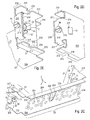
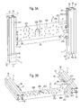
- a mounting frame consists of at least two mutually spaced vertical supports 1, which are anchored to a support structure of the building - eg a rear wall - and at least one detachably inserted between the vertical supports 1 dashboard 2.
- the corner connectors 4 can be clamped with the screws 49 .
- For larger structures will provide more than two vertical supports 1 , which are placed in a vertical plane and are equipped with a variety of fitting plates 2 .
- the instrument panels 2 are intended for holding fittings - such as valves, distributors, toilet cisterns or meter - and connecting lines, including drain pipes.
- a vertical support 1 is preferably a hollow profile of square cross-section in principle is used, which has the sides 11-14 , wherein on each side 11-14 a groove 15 extends, which is opposite to the protruding corners 16 set back inside and at the transition to the Corners 16 each has an undercut 150 .
- the groove 15 thus results in a T-shaped or dovetail-shaped cross-sectional geometry.
- the profile of such vertical supports 1 is known per se and eg in the EP 0 579 578 B1 shown.
- one will use the same profile for the transverse supports 1 ' .
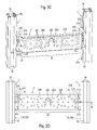
- the instrument panel 2 has between the outer ends of the existing adapters 21 has a central leg 20 with the vertical base surface 200 and each one above or below thereof outgoing bend 204, so that there is a flat U-profile.
- the two adapters 21 are formed at right angles, from the longitudinal extent of the center leg 20 in the space facing bends of the U-profile.
- a grid of first holes 201 and a bendable fastener 203 having a second hole 202 are provided for attachment of various fittings. For example, you can bend the fastener 203 horizontally in the room and attach a clamp that in turn holds a tube.
- each adapter 21 initially has a base surface 210 and the first two bends 214 , each with a recess 215, a preceding front segment 212 and a rear segment lying behind 213.
- Each of the base surface 210th is perpendicular to a second outwardly facing bend 216 , the latter are pre-set parallel to the plane of the base surface 200 in the room.
- the second bends 216 terminate with a third bend 218.
- the second bend 216 goes up and at the bottom a right angle bent claw 217 , which extends parallel to the direction of the first bend 214 .
- the second bends 216 are penetrated in the center each by a screw 39 which sits in a threaded hole 219 , which may be present directly in the second bend 216 or is provided by a nut which is preferably fixed to the back of the second bend 216 , eg welded on.
- the tip of the screw shaft engages axially fixed, but freely rotatable by a disc 33 in the in principle cross-shaped clamping part 3 , which has pairwise opposite first and second claws 31,32 .
- a slot 211 is provided, which allows the thorough seating of one of the two first claws 31 .
- the dashboard 2 is releasably inserted between two adjacent vertical supports 1 .
- the rear, inwardly directed corner 16 of the two vertical supports 1 in the recesses 215 of each present at the top and bottom of the two adapters 21 first bend 214 to lie.
- the front segments 212 protrude, in principle, into the respective groove 15 in a form-fitting manner, while the rear segments 213 protrude rearward.
- the third bend 218 of both adapters 21 engage in the front undercut 150 and the first claw 31 facing the respective vertical support 1 enters the rear undercut 150 of the respective groove 15 .
- the outer edges of the adapter claws 217 are based in the associated groove 15 .
- the respective pair of second claws 32 on each clamping part 3 comes to rest as an additional stabilizing contour between the adapter base surface 210 and the corner 16 covered by the first claw 31 .
- the inwardly facing first claw 31 extends through the slot 211 in the adapter base 210.
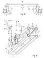
- the head 390 of the screw 39 for clamping the clamping part 3 is accessible from the room.
- the screw shaft 391 inserted with its external thread 392 in the internal thread 219 at the second bend 216.
- Toward the free end of the screw shaft 391 is provided with a collar 395 , from the shaft 391 continues as unthreaded pin 393 .
- This pin 393 penetrates a disc 33, which abuts the collar 395 and is inserted between the clamping part 3 .
- At the free end of the pin 393 has a thickening 394 - eg generated as Aufpilzung - so that the clamping member 3 is axially fixed on the rotatable screw 39 is arranged.
- the third bend 218 and one of the two first claws 31 are pressed more intensively into the two undercuts 150 of the groove 15 , at the same time the other first claw 31 is stronger in the slot 211 on the adapter base 210 .
- its two first claws 31 are moved out of their seats, ie, the rear undercut 150 and the slot 211 , until the adapter 21 can be removed from the vertical support 1 by entrainment of the clamping part 3 .
Landscapes
- Health & Medical Sciences (AREA)
- Life Sciences & Earth Sciences (AREA)
- Engineering & Computer Science (AREA)
- Hydrology & Water Resources (AREA)
- Public Health (AREA)
- Water Supply & Treatment (AREA)
- Mutual Connection Of Rods And Tubes (AREA)
- Body Structure For Vehicles (AREA)
- Connection Of Plates (AREA)
Applications Claiming Priority (1)
| Application Number | Priority Date | Filing Date | Title |
|---|---|---|---|
| CH4472005 | 2005-03-15 |
Publications (3)
| Publication Number | Publication Date |
|---|---|
| EP1703030A2 true EP1703030A2 (fr) | 2006-09-20 |
| EP1703030A3 EP1703030A3 (fr) | 2014-08-13 |
| EP1703030B1 EP1703030B1 (fr) | 2017-03-08 |
Family
ID=36577447
Family Applications (1)
| Application Number | Title | Priority Date | Filing Date |
|---|---|---|---|
| EP06405026.3A Expired - Lifetime EP1703030B1 (fr) | 2005-03-15 | 2006-01-23 | Cadre de montage pour une installation sanitaire |
Country Status (1)
| Country | Link |
|---|---|
| EP (1) | EP1703030B1 (fr) |
Cited By (7)
| Publication number | Priority date | Publication date | Assignee | Title |
|---|---|---|---|---|
| ITTO20100914A1 (it) * | 2010-11-18 | 2012-05-19 | Errepierre S R L | Telaio per il montaggio di apparecchi idrosanitari in tramezzi di cartongesso |
| EP3470587A1 (fr) * | 2017-10-16 | 2019-04-17 | GROHEDAL Sanitärsysteme GmbH | Dispositif de fixation d'un wc à un mur et agencement wc doté d'un dispositif correspondant |
| IT201800003177A1 (it) * | 2018-03-01 | 2019-09-01 | Gia S P A | Struttura di supporto di un sanitario |
| CN110250966A (zh) * | 2019-07-27 | 2019-09-20 | 浙江健龙厨卫股份有限公司 | 一种淋浴屏 |
| EP3964655A1 (fr) * | 2020-09-02 | 2022-03-09 | Geberit International AG | Élément de fixation |
| DE202024100400U1 (de) * | 2024-01-26 | 2025-02-04 | Cirrus B.V., Zweigniederlassung Neustadt/Wied | Halterelement zur Fixierung von Sanitärrohren |
| DE202024100539U1 (de) * | 2024-02-05 | 2025-02-14 | Cirrus B.V., Zweigniederlassung Neustadt/Wied | Stanz- und/oder Biegeteil und Vorwand-Montagerahmen für eine Sanitärinstallation |
Family Cites Families (3)
| Publication number | Priority date | Publication date | Assignee | Title |
|---|---|---|---|---|
| FR2585801B1 (fr) * | 1985-08-01 | 1988-01-29 | Ceralnor | Dispositif d'assemblage de profiles comportant des bras basculant autour d'une zone d'articulation |
| EP0404726B1 (fr) * | 1989-06-20 | 1993-08-11 | Geberit AG | Dispositif pour la connexion de rails en forme de C, en particulier rails de montage |
| NO301295B1 (no) * | 1994-03-28 | 1997-10-06 | Geberit Technik Ag | Stativ med i det minste to på tvers av hverandre forlöpende hulprofilstenger |
-
2006
- 2006-01-23 EP EP06405026.3A patent/EP1703030B1/fr not_active Expired - Lifetime
Cited By (8)
| Publication number | Priority date | Publication date | Assignee | Title |
|---|---|---|---|---|
| ITTO20100914A1 (it) * | 2010-11-18 | 2012-05-19 | Errepierre S R L | Telaio per il montaggio di apparecchi idrosanitari in tramezzi di cartongesso |
| EP3470587A1 (fr) * | 2017-10-16 | 2019-04-17 | GROHEDAL Sanitärsysteme GmbH | Dispositif de fixation d'un wc à un mur et agencement wc doté d'un dispositif correspondant |
| DE102017009631A1 (de) * | 2017-10-16 | 2019-04-18 | GROHEDAL Sanitärsysteme GmbH | Vorrichtung zur Befestigung eines WCs an einer Wand und WC-Anordnung mit einer entsprechenden Vorrichtung |
| IT201800003177A1 (it) * | 2018-03-01 | 2019-09-01 | Gia S P A | Struttura di supporto di un sanitario |
| CN110250966A (zh) * | 2019-07-27 | 2019-09-20 | 浙江健龙厨卫股份有限公司 | 一种淋浴屏 |
| EP3964655A1 (fr) * | 2020-09-02 | 2022-03-09 | Geberit International AG | Élément de fixation |
| DE202024100400U1 (de) * | 2024-01-26 | 2025-02-04 | Cirrus B.V., Zweigniederlassung Neustadt/Wied | Halterelement zur Fixierung von Sanitärrohren |
| DE202024100539U1 (de) * | 2024-02-05 | 2025-02-14 | Cirrus B.V., Zweigniederlassung Neustadt/Wied | Stanz- und/oder Biegeteil und Vorwand-Montagerahmen für eine Sanitärinstallation |
Also Published As
| Publication number | Publication date |
|---|---|
| EP1703030B1 (fr) | 2017-03-08 |
| EP1703030A3 (fr) | 2014-08-13 |
Similar Documents
| Publication | Publication Date | Title |
|---|---|---|
| EP0493319A2 (fr) | Connexion de deux profilés, profilés pour un système de support et système de support pour appareils sanitaires ainsi que procédé pour la production d'un tel système support | |
| EP1135616A1 (fr) | Assemblage en t de deux barreaux profiles | |
| WO2001029472A1 (fr) | Systeme de canalisation | |
| EP3296474B1 (fr) | Dispositif de fixation pour un objet sanitaire suspendu au mur et ensemble de fixation | |
| EP4093241B1 (fr) | Dispositif de liaison, système structural et étagère | |
| EP1541878A2 (fr) | Système de fixation | |
| EP1703030B1 (fr) | Cadre de montage pour une installation sanitaire | |
| WO1988003203A2 (fr) | Systeme modulaire de construction | |
| EP3214235B1 (fr) | Systeme de connection de pieces préfabriquées en beton | |
| DE4002420A1 (de) | Anker fuer die befestigung von fassadenplatten an einer wand | |
| EP1706652B1 (fr) | Ensemble d'assemblage de deux profiles creux continus | |
| EP1640524B1 (fr) | Kit de construction pour réaliser une structure de support, en particulier pour tubes | |
| EP2138069B1 (fr) | Kit de production d'une table multifonctionnelle d'écriture ou de travail | |
| EP1982020A1 (fr) | Dispositif de maintien conçu pour maintenir un appareil encastrable sur un plan de travail | |
| EP1651873A1 (fr) | Dispositif comportant deux profiles creux assembles par une vis et outil correspondant | |
| EP3296473A1 (fr) | Dispositif de fixation pour un objet sanitaire suspendu au mur, ensemble de fixation et procédé de démontage d'un objet sanitaire suspendu au mur | |
| DE102005060817B4 (de) | Nutenstein, Ankerstein, Profilverbindersystem und Profilverbund | |
| EP3913156B1 (fr) | Utilisation d'un cadre de fixation pour un dispositif d'actionnement ou pour une imitation d'un dispositif d'actionnement destiné au fonctionnement d'une installation sanitaire | |
| EP1981384A1 (fr) | Dispositif de maintien conçu pour maintenir un appareil encastrable sur un plan de travail | |
| DE10213725A1 (de) | Montagesystem | |
| EP3973818A1 (fr) | Paroi latérale de tiroir | |
| EP4114150A1 (fr) | Ensemble d'extension | |
| EP3441535B1 (fr) | Dispositif de fixation d'une unité sanitaire | |
| DE202004004783U1 (de) | Hülse und darin einsteckbarer Arm als Aufhängevorrichtung | |
| DE19836226C2 (de) | Vorrichtung zum Verbinden von zwei Profilschienen |
Legal Events
| Date | Code | Title | Description |
|---|---|---|---|
| PUAI | Public reference made under article 153(3) epc to a published international application that has entered the european phase |
Free format text: ORIGINAL CODE: 0009012 |
|
| AK | Designated contracting states |
Kind code of ref document: A2 Designated state(s): AT BE BG CH CY CZ DE DK EE ES FI FR GB GR HU IE IS IT LI LT LU LV MC NL PL PT RO SE SI SK TR |
|
| AX | Request for extension of the european patent |
Extension state: AL BA HR MK YU |
|
| RAP1 | Party data changed (applicant data changed or rights of an application transferred) |
Owner name: GEORG FISCHER JRG AG |
|
| RIC1 | Information provided on ipc code assigned before grant |
Ipc: E03C 1/326 20060101AFI20140326BHEP |
|
| REG | Reference to a national code |
Ref country code: DE Ref legal event code: R079 Ref document number: 502006015400 Country of ref document: DE Free format text: PREVIOUS MAIN CLASS: E03D0011140000 Ipc: E03C0001326000 |
|
| PUAL | Search report despatched |
Free format text: ORIGINAL CODE: 0009013 |
|
| AK | Designated contracting states |
Kind code of ref document: A3 Designated state(s): AT BE BG CH CY CZ DE DK EE ES FI FR GB GR HU IE IS IT LI LT LU LV MC NL PL PT RO SE SI SK TR |
|
| AX | Request for extension of the european patent |
Extension state: AL BA HR MK YU |
|
| RIC1 | Information provided on ipc code assigned before grant |
Ipc: E03C 1/326 20060101AFI20140710BHEP |
|
| 17P | Request for examination filed |
Effective date: 20150129 |
|
| RBV | Designated contracting states (corrected) |
Designated state(s): AT BE BG CH CY CZ DE DK EE ES FI FR GB GR HU IE IS IT LI LT LU LV MC NL PL PT RO SE SI SK TR |
|
| AKX | Designation fees paid |
Designated state(s): AT BE BG CH CY CZ DE DK EE ES FI FR GB GR HU IE IS IT LI LT LU LV MC NL PL PT RO SE SI SK TR |
|
| AXX | Extension fees paid |
Extension state: HR Extension state: BA Extension state: YU Extension state: MK Extension state: AL |
|
| 17Q | First examination report despatched |
Effective date: 20151218 |
|
| GRAP | Despatch of communication of intention to grant a patent |
Free format text: ORIGINAL CODE: EPIDOSNIGR1 |
|
| INTG | Intention to grant announced |
Effective date: 20160930 |
|
| GRAS | Grant fee paid |
Free format text: ORIGINAL CODE: EPIDOSNIGR3 |
|
| GRAA | (expected) grant |
Free format text: ORIGINAL CODE: 0009210 |
|
| AK | Designated contracting states |
Kind code of ref document: B1 Designated state(s): AT BE BG CH CY CZ DE DK EE ES FI FR GB GR HU IE IS IT LI LT LU LV MC NL PL PT RO SE SI SK TR |
|
| REG | Reference to a national code |
Ref country code: GB Ref legal event code: FG4D Free format text: NOT ENGLISH |
|
| REG | Reference to a national code |
Ref country code: CH Ref legal event code: EP Ref country code: CH Ref legal event code: NV Representative=s name: GEORG FISCHER AG, CH Ref country code: AT Ref legal event code: REF Ref document number: 873655 Country of ref document: AT Kind code of ref document: T Effective date: 20170315 |
|
| REG | Reference to a national code |
Ref country code: IE Ref legal event code: FG4D Free format text: LANGUAGE OF EP DOCUMENT: GERMAN |
|
| REG | Reference to a national code |
Ref country code: DE Ref legal event code: R096 Ref document number: 502006015400 Country of ref document: DE |
|
| REG | Reference to a national code |
Ref country code: LT Ref legal event code: MG4D |
|
| REG | Reference to a national code |
Ref country code: NL Ref legal event code: MP Effective date: 20170308 |
|
| PG25 | Lapsed in a contracting state [announced via postgrant information from national office to epo] |
Ref country code: GR Free format text: LAPSE BECAUSE OF FAILURE TO SUBMIT A TRANSLATION OF THE DESCRIPTION OR TO PAY THE FEE WITHIN THE PRESCRIBED TIME-LIMIT Effective date: 20170609 Ref country code: FI Free format text: LAPSE BECAUSE OF FAILURE TO SUBMIT A TRANSLATION OF THE DESCRIPTION OR TO PAY THE FEE WITHIN THE PRESCRIBED TIME-LIMIT Effective date: 20170308 Ref country code: LT Free format text: LAPSE BECAUSE OF FAILURE TO SUBMIT A TRANSLATION OF THE DESCRIPTION OR TO PAY THE FEE WITHIN THE PRESCRIBED TIME-LIMIT Effective date: 20170308 |
|
| PG25 | Lapsed in a contracting state [announced via postgrant information from national office to epo] |
Ref country code: BG Free format text: LAPSE BECAUSE OF FAILURE TO SUBMIT A TRANSLATION OF THE DESCRIPTION OR TO PAY THE FEE WITHIN THE PRESCRIBED TIME-LIMIT Effective date: 20170608 Ref country code: LV Free format text: LAPSE BECAUSE OF FAILURE TO SUBMIT A TRANSLATION OF THE DESCRIPTION OR TO PAY THE FEE WITHIN THE PRESCRIBED TIME-LIMIT Effective date: 20170308 Ref country code: SE Free format text: LAPSE BECAUSE OF FAILURE TO SUBMIT A TRANSLATION OF THE DESCRIPTION OR TO PAY THE FEE WITHIN THE PRESCRIBED TIME-LIMIT Effective date: 20170308 Ref country code: ES Free format text: LAPSE BECAUSE OF FAILURE TO SUBMIT A TRANSLATION OF THE DESCRIPTION OR TO PAY THE FEE WITHIN THE PRESCRIBED TIME-LIMIT Effective date: 20170308 |
|
| PG25 | Lapsed in a contracting state [announced via postgrant information from national office to epo] |
Ref country code: NL Free format text: LAPSE BECAUSE OF FAILURE TO SUBMIT A TRANSLATION OF THE DESCRIPTION OR TO PAY THE FEE WITHIN THE PRESCRIBED TIME-LIMIT Effective date: 20170308 |
|
| PG25 | Lapsed in a contracting state [announced via postgrant information from national office to epo] |
Ref country code: CZ Free format text: LAPSE BECAUSE OF FAILURE TO SUBMIT A TRANSLATION OF THE DESCRIPTION OR TO PAY THE FEE WITHIN THE PRESCRIBED TIME-LIMIT Effective date: 20170308 Ref country code: RO Free format text: LAPSE BECAUSE OF FAILURE TO SUBMIT A TRANSLATION OF THE DESCRIPTION OR TO PAY THE FEE WITHIN THE PRESCRIBED TIME-LIMIT Effective date: 20170308 Ref country code: EE Free format text: LAPSE BECAUSE OF FAILURE TO SUBMIT A TRANSLATION OF THE DESCRIPTION OR TO PAY THE FEE WITHIN THE PRESCRIBED TIME-LIMIT Effective date: 20170308 Ref country code: SK Free format text: LAPSE BECAUSE OF FAILURE TO SUBMIT A TRANSLATION OF THE DESCRIPTION OR TO PAY THE FEE WITHIN THE PRESCRIBED TIME-LIMIT Effective date: 20170308 |
|
| PG25 | Lapsed in a contracting state [announced via postgrant information from national office to epo] |
Ref country code: PL Free format text: LAPSE BECAUSE OF FAILURE TO SUBMIT A TRANSLATION OF THE DESCRIPTION OR TO PAY THE FEE WITHIN THE PRESCRIBED TIME-LIMIT Effective date: 20170308 Ref country code: IS Free format text: LAPSE BECAUSE OF FAILURE TO SUBMIT A TRANSLATION OF THE DESCRIPTION OR TO PAY THE FEE WITHIN THE PRESCRIBED TIME-LIMIT Effective date: 20170708 Ref country code: PT Free format text: LAPSE BECAUSE OF FAILURE TO SUBMIT A TRANSLATION OF THE DESCRIPTION OR TO PAY THE FEE WITHIN THE PRESCRIBED TIME-LIMIT Effective date: 20170710 |
|
| REG | Reference to a national code |
Ref country code: DE Ref legal event code: R097 Ref document number: 502006015400 Country of ref document: DE |
|
| PLBE | No opposition filed within time limit |
Free format text: ORIGINAL CODE: 0009261 |
|
| STAA | Information on the status of an ep patent application or granted ep patent |
Free format text: STATUS: NO OPPOSITION FILED WITHIN TIME LIMIT |
|
| REG | Reference to a national code |
Ref country code: FR Ref legal event code: PLFP Year of fee payment: 13 |
|
| PG25 | Lapsed in a contracting state [announced via postgrant information from national office to epo] |
Ref country code: DK Free format text: LAPSE BECAUSE OF FAILURE TO SUBMIT A TRANSLATION OF THE DESCRIPTION OR TO PAY THE FEE WITHIN THE PRESCRIBED TIME-LIMIT Effective date: 20170308 |
|
| 26N | No opposition filed |
Effective date: 20171211 |
|
| PG25 | Lapsed in a contracting state [announced via postgrant information from national office to epo] |
Ref country code: SI Free format text: LAPSE BECAUSE OF FAILURE TO SUBMIT A TRANSLATION OF THE DESCRIPTION OR TO PAY THE FEE WITHIN THE PRESCRIBED TIME-LIMIT Effective date: 20170308 Ref country code: IT Free format text: LAPSE BECAUSE OF FAILURE TO SUBMIT A TRANSLATION OF THE DESCRIPTION OR TO PAY THE FEE WITHIN THE PRESCRIBED TIME-LIMIT Effective date: 20170308 |
|
| REG | Reference to a national code |
Ref country code: IE Ref legal event code: MM4A |
|
| REG | Reference to a national code |
Ref country code: BE Ref legal event code: MM Effective date: 20180131 |
|
| PG25 | Lapsed in a contracting state [announced via postgrant information from national office to epo] |
Ref country code: BE Free format text: LAPSE BECAUSE OF NON-PAYMENT OF DUE FEES Effective date: 20180131 |
|
| PG25 | Lapsed in a contracting state [announced via postgrant information from national office to epo] |
Ref country code: IE Free format text: LAPSE BECAUSE OF NON-PAYMENT OF DUE FEES Effective date: 20180123 |
|
| PG25 | Lapsed in a contracting state [announced via postgrant information from national office to epo] |
Ref country code: TR Free format text: LAPSE BECAUSE OF FAILURE TO SUBMIT A TRANSLATION OF THE DESCRIPTION OR TO PAY THE FEE WITHIN THE PRESCRIBED TIME-LIMIT Effective date: 20170308 |
|
| PG25 | Lapsed in a contracting state [announced via postgrant information from national office to epo] |
Ref country code: HU Free format text: LAPSE BECAUSE OF FAILURE TO SUBMIT A TRANSLATION OF THE DESCRIPTION OR TO PAY THE FEE WITHIN THE PRESCRIBED TIME-LIMIT; INVALID AB INITIO Effective date: 20060123 |
|
| PG25 | Lapsed in a contracting state [announced via postgrant information from national office to epo] |
Ref country code: CY Free format text: LAPSE BECAUSE OF FAILURE TO SUBMIT A TRANSLATION OF THE DESCRIPTION OR TO PAY THE FEE WITHIN THE PRESCRIBED TIME-LIMIT Effective date: 20170308 |
|
| P01 | Opt-out of the competence of the unified patent court (upc) registered |
Effective date: 20230529 |
|
| PGFP | Annual fee paid to national office [announced via postgrant information from national office to epo] |
Ref country code: LU Payment date: 20250128 Year of fee payment: 20 |
|
| PGFP | Annual fee paid to national office [announced via postgrant information from national office to epo] |
Ref country code: MC Payment date: 20250123 Year of fee payment: 20 |
|
| PGFP | Annual fee paid to national office [announced via postgrant information from national office to epo] |
Ref country code: DE Payment date: 20250121 Year of fee payment: 20 |
|
| PGFP | Annual fee paid to national office [announced via postgrant information from national office to epo] |
Ref country code: AT Payment date: 20250122 Year of fee payment: 20 Ref country code: CH Payment date: 20250201 Year of fee payment: 20 |
|
| PGFP | Annual fee paid to national office [announced via postgrant information from national office to epo] |
Ref country code: FR Payment date: 20250124 Year of fee payment: 20 |
|
| PGFP | Annual fee paid to national office [announced via postgrant information from national office to epo] |
Ref country code: GB Payment date: 20250128 Year of fee payment: 20 |
|
| REG | Reference to a national code |
Ref country code: CH Ref legal event code: H14 Free format text: ST27 STATUS EVENT CODE: U-0-0-H10-H14 (AS PROVIDED BY THE NATIONAL OFFICE) Effective date: 20260123 Ref country code: DE Ref legal event code: R071 Ref document number: 502006015400 Country of ref document: DE |
|
| REG | Reference to a national code |
Ref country code: GB Ref legal event code: PE20 Expiry date: 20260122 |
|
| REG | Reference to a national code |
Ref country code: AT Ref legal event code: MK07 Ref document number: 873655 Country of ref document: AT Kind code of ref document: T Effective date: 20260123 |