EP1703065A2 - Profilé creux renforcé - Google Patents
Profilé creux renforcé Download PDFInfo
- Publication number
- EP1703065A2 EP1703065A2 EP05011894A EP05011894A EP1703065A2 EP 1703065 A2 EP1703065 A2 EP 1703065A2 EP 05011894 A EP05011894 A EP 05011894A EP 05011894 A EP05011894 A EP 05011894A EP 1703065 A2 EP1703065 A2 EP 1703065A2
- Authority
- EP
- European Patent Office
- Prior art keywords
- hollow chamber
- reinforcing element
- profile
- clamping
- wall
- Prior art date
- Legal status (The legal status is an assumption and is not a legal conclusion. Google has not performed a legal analysis and makes no representation as to the accuracy of the status listed.)
- Withdrawn
Links
- 230000003014 reinforcing effect Effects 0.000 claims abstract description 87
- 239000002861 polymer material Substances 0.000 claims abstract description 5
- 238000003780 insertion Methods 0.000 description 8
- 230000037431 insertion Effects 0.000 description 8
- 238000006073 displacement reaction Methods 0.000 description 6
- 210000002105 tongue Anatomy 0.000 description 6
- 238000000034 method Methods 0.000 description 5
- 230000002441 reversible effect Effects 0.000 description 5
- 238000005452 bending Methods 0.000 description 4
- 239000000463 material Substances 0.000 description 3
- 238000004519 manufacturing process Methods 0.000 description 2
- 230000002787 reinforcement Effects 0.000 description 2
- 230000003068 static effect Effects 0.000 description 2
- 230000000295 complement effect Effects 0.000 description 1
- 239000002131 composite material Substances 0.000 description 1
- 238000010276 construction Methods 0.000 description 1
- 230000007423 decrease Effects 0.000 description 1
- 230000000694 effects Effects 0.000 description 1
- 230000002349 favourable effect Effects 0.000 description 1
- 239000011521 glass Substances 0.000 description 1
- 238000010438 heat treatment Methods 0.000 description 1
- 238000009434 installation Methods 0.000 description 1
- 229910052751 metal Inorganic materials 0.000 description 1
- 230000005855 radiation Effects 0.000 description 1
- 125000006850 spacer group Chemical group 0.000 description 1
- 239000002023 wood Substances 0.000 description 1
Images


Classifications
-
- E—FIXED CONSTRUCTIONS
- E06—DOORS, WINDOWS, SHUTTERS, OR ROLLER BLINDS IN GENERAL; LADDERS
- E06B—FIXED OR MOVABLE CLOSURES FOR OPENINGS IN BUILDINGS, VEHICLES, FENCES OR LIKE ENCLOSURES IN GENERAL, e.g. DOORS, WINDOWS, BLINDS, GATES
- E06B9/00—Screening or protective devices for wall or similar openings, with or without operating or securing mechanisms; Closures of similar construction
- E06B9/02—Shutters, movable grilles, or other safety closing devices, e.g. against burglary
- E06B9/08—Roll-type closures
- E06B9/11—Roller shutters
- E06B9/15—Roller shutters with closing members formed of slats or the like
-
- E—FIXED CONSTRUCTIONS
- E06—DOORS, WINDOWS, SHUTTERS, OR ROLLER BLINDS IN GENERAL; LADDERS
- E06B—FIXED OR MOVABLE CLOSURES FOR OPENINGS IN BUILDINGS, VEHICLES, FENCES OR LIKE ENCLOSURES IN GENERAL, e.g. DOORS, WINDOWS, BLINDS, GATES
- E06B3/00—Window sashes, door leaves, or like elements for closing wall or like openings; Layout of fixed or moving closures, e.g. windows in wall or like openings; Features of rigidly-mounted outer frames relating to the mounting of wing frames
- E06B3/04—Wing frames not characterised by the manner of movement
- E06B3/06—Single frames
- E06B3/08—Constructions depending on the use of specified materials
- E06B3/20—Constructions depending on the use of specified materials of plastics
- E06B3/22—Hollow frames
- E06B3/221—Hollow frames with the frame member having local reinforcements in some parts of its cross-section or with a filled cavity
- E06B3/222—Hollow frames with the frame member having local reinforcements in some parts of its cross-section or with a filled cavity with internal prefabricated reinforcing section members inserted after manufacturing of the hollow frame
-
- E—FIXED CONSTRUCTIONS
- E06—DOORS, WINDOWS, SHUTTERS, OR ROLLER BLINDS IN GENERAL; LADDERS
- E06B—FIXED OR MOVABLE CLOSURES FOR OPENINGS IN BUILDINGS, VEHICLES, FENCES OR LIKE ENCLOSURES IN GENERAL, e.g. DOORS, WINDOWS, BLINDS, GATES
- E06B9/00—Screening or protective devices for wall or similar openings, with or without operating or securing mechanisms; Closures of similar construction
- E06B9/02—Shutters, movable grilles, or other safety closing devices, e.g. against burglary
-
- E—FIXED CONSTRUCTIONS
- E06—DOORS, WINDOWS, SHUTTERS, OR ROLLER BLINDS IN GENERAL; LADDERS
- E06B—FIXED OR MOVABLE CLOSURES FOR OPENINGS IN BUILDINGS, VEHICLES, FENCES OR LIKE ENCLOSURES IN GENERAL, e.g. DOORS, WINDOWS, BLINDS, GATES
- E06B3/00—Window sashes, door leaves, or like elements for closing wall or like openings; Layout of fixed or moving closures, e.g. windows in wall or like openings; Features of rigidly-mounted outer frames relating to the mounting of wing frames
- E06B3/04—Wing frames not characterised by the manner of movement
- E06B3/06—Single frames
- E06B3/08—Constructions depending on the use of specified materials
- E06B3/20—Constructions depending on the use of specified materials of plastics
- E06B3/22—Hollow frames
- E06B3/221—Hollow frames with the frame member having local reinforcements in some parts of its cross-section or with a filled cavity
- E06B3/222—Hollow frames with the frame member having local reinforcements in some parts of its cross-section or with a filled cavity with internal prefabricated reinforcing section members inserted after manufacturing of the hollow frame
- E06B2003/225—Means for stabilising the insert
-
- E—FIXED CONSTRUCTIONS
- E06—DOORS, WINDOWS, SHUTTERS, OR ROLLER BLINDS IN GENERAL; LADDERS
- E06B—FIXED OR MOVABLE CLOSURES FOR OPENINGS IN BUILDINGS, VEHICLES, FENCES OR LIKE ENCLOSURES IN GENERAL, e.g. DOORS, WINDOWS, BLINDS, GATES
- E06B9/00—Screening or protective devices for wall or similar openings, with or without operating or securing mechanisms; Closures of similar construction
- E06B9/02—Shutters, movable grilles, or other safety closing devices, e.g. against burglary
- E06B9/08—Roll-type closures
- E06B9/11—Roller shutters
- E06B9/15—Roller shutters with closing members formed of slats or the like
- E06B2009/1505—Slat details
- E06B2009/1516—Means to increase resistance against bending
Definitions
- the invention relates to a hollow chamber profile made of polymer material, in the hollow chamber of which a reinforcing element is arranged and which is improved in terms of its flexural rigidity and elongation.
- Hollow chamber profiles are widely used in various fields. In large quantities, these are manufactured as window profiles, roller shutter profiles, cover profiles and ornamental profiles.
- a known application also relates to slats, which are arranged as sun visors / window panels on windows, where they act as light and / or privacy. These panels are also known as folding shutters.
- reinforcing elements are arranged in the hollow chamber of the profiles, which are in contact with the wall of the hollow chamber of the profile and depending on the design increase the flexural rigidity and / or limit or reduce the thermal expansion of the profile. These reinforcing elements are also referred to as reinforcing profiles.
- the DE 295 13 102 U1 discloses a reinforcing profile in the hollow chamber of a window profile on projecting into the hollow chamber spacer webs, emanating from the walls bounding the hollow chamber, and so to establish contact between the reinforcing profile and window profile, which has an advantageous effect on the flexural rigidity of the thus equipped hollow chamber profile.
- Window profiles are produced in various designs and to complete the respective systems in a variety of profile cross sections. Almost without exception, these are hollow chamber profiles. Window construction profiles are assembled into frame arrangements. They carry the glass pane and thus high loads, which also result in unfavorable boundary conditions, such as high wind, in large forces to be guided, result. The stiffening of the hollow chamber profiles is therefore necessary and known, it is accomplished by inserting metal elements in the hollow chambers of the profiles.
- a disadvantage of the known techniques for reinforcing hollow chamber profiles is that the insertion is difficult and therefore associated with great expense. It is also possible to damage the hollow chamber profile during insertion of the reinforcing element. All this requires that the insertion of such elements is associated with a lot of effort and thus also costs in no insignificant amount.
- the invention is therefore based on the object to modify a hollow chamber profile so that an easy insertion of a reinforcing element is possible in the hollow chamber, wherein the reinforcing element is securely fixed after insertion and the reinforcing element without restriction improves the flexural rigidity and elongation of the hollow chamber profile.
- the walls or sections of the walls which delimit the hollow chamber in the interior of a hollow-chamber profile are to be interpreted as reversibly yielding during the introduction of the reinforcing element, that is to say they offer little resistance to the introduction itself. After the introduction of the reinforcing element, these largely return to their original shape and thus clamp the inserted reinforcing element and ensure that no unintentional slipping or sliding away can take place.
- the reinforcing element is then fixed in particular non-positively in the hollow chamber and can advantageously improve the bending stiffness and elongation of the profile.
- At least one wall of the hollow chamber profile is designed so that the determination of the reinforcing element is made possible by clamping.
- Another possibility is to arrange a clamping element on the wall of the hollow chamber profile.
- clamping element in the form of a integrally formed on the wall spring tongue, which clamps the object under bias.
- the invention proposes to provide at least one resilient element, which protrudes from a wall of the hollow chamber in the hollow chamber, and is formed integrally therewith.
- the resilient element may be a spring tongue or a clamping spring, which applies a spring force that can be used for fixing the reinforcing element in the hollow chamber of the profile.
- the resilient element is preferably designed so that it applies a spring force in the direction of the reinforcing element in order to set this against slipping and sliding away and thus secure.
- the resilient element is preferably arranged so that the reinforcing element in the hollow chamber of the profile under the influence of the spring force of the resilient element is pressed in sections against an opposite wall delimiting the hollow chamber.
- the hollow chamber profile can be reversibly deformed in the cross section of the hollow chamber by a force which does not result from the insertion of the reinforcing element, and the reinforcing element can be inserted.
- the force can for example be applied in sections from the outside of the profile, whereby the deformation takes place.
- the reinforcing element is arranged in the hollow chamber of the profile and fixed in a clamping manner, then it has a favorable effect on the bending stiffness and the longitudinal extent of the profile.
- the reinforcing element may have an outer contour which is formed in profile substantially complementary to the inner contour of the hollow chamber.
- the reinforcing element bears resiliently against at least two inner walls of the hollow chamber which are approximately opposite each other and is supported at least in sections on these inner walls, whereby the reinforcement of the hollow profile is achieved.
- the clamping element can be designed such that at least one wall of the hollow chamber profile delimiting the hollow chamber is designed such that this wall can be reversibly transferred from a first state to a second state by an externally applied force, thereby resulting in a change in cross section of the hollow chamber comes that a reinforcing element can be easily inserted.
- the second state of the profile is characterized in that by a reversible change in shape of the profile, the cross section of the hollow chamber is at least partially enlarged and thus offers the possibility that the reinforcing element can be easily inserted.
- the profile After removal of the externally applied force, the profile reversibly returns to the first state and defines the inserted reinforcing element by clamping. Slipping or sliding away of the reinforcing element is reliably prevented in this way.
- the hollow chamber profile can optionally be acted upon by a force from the outside, wherein the spring element recedes a piece and allows the insertion of the reinforcing element.
- Another possibility is to introduce the reinforcing profile in the hollow chamber against the resistance of the spring element, overcoming the initial static friction. Once the insertion process is completed, the static friction between spring element and reinforcing element and the displacement or slippage is thus prevented.
- the spring element which protrudes into the hollow chamber can also be supplemented so that on the spring element and the reinforcing element mutually corresponding interlocking elements, such as a latching lug and correspondingly shaped counterparts, which are designed as recesses in a corresponding surface of the reinforcing element, are provided.
- This embodiment of the invention can also be applied to the already described special designs of the walls bounding the hollow chamber, by the walls and the reinforcing element corresponding latching elements are assigned, which engage with each other so that a displacement of the reinforcing element in the hollow chamber is even better prevented.
- the reinforcing element can also be fixed in the hollow chamber of the profile by screwing.
- the reinforcing element is designed so that material selection and wall thickness are matched to the screwing process.
- the reinforcing element By screwing the reinforcing element in the hollow chamber, the reinforcing element is fixed immovably in the hollow chamber.
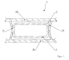
- a hollow chamber profile is shown in cross-section, in the hollow chamber, a reinforcing element is arranged, wherein the reinforcing element by two opposite the hollow chamber bounding walls, each of which convexly curved towards the chamber convexly curved and designed in these sections, is determined by clamping.
- a reinforcing profile (4) is arranged such that two walls (3a, c) clamp the reinforcing profile (4), in that these walls (3a, c) are partially in abutment with the reinforcing element (4).
- the walls (3a, c) face each other and act with a force on the reinforcing element (4).
- the forces transmitted through the walls (3a, c) to the reinforcing element (4) act against each other.
- the reinforcing element (4) is thereby securely fixed in the hollow chamber (2) and secured against lateral slippage / displacement.
- the hollow chamber profile can also be designed so that only a wall cambered towards the chamber curved and designed in sections projecting into it, wherein the clamping of this wall is then communicated through the reinforcing element to a wall that can be designed differently.
- Fig. 2 shows a hollow chamber profile in cross section, in the hollow chamber, a reinforcing element is arranged, which is fixed by clamping two opposing the hollow chamber bounding each accordion-like walls.
- a reinforcing profile (4) is arranged such that two walls (3b, d) clamp the reinforcing profile (4), in that these walls (3b, d) are partially in abutment with the reinforcing element (4).
- the walls (3b, d) face each other and act with a force on the reinforcing element (4). ).
- the forces transmitted through the walls (3b, d) to the reinforcing element (4) act against each other.
- the reinforcing element (4) is thereby securely fixed in the hollow chamber (2) and secured against lateral slippage / displacement.
- a reinforcing element is arranged, which is defined by a spring tongue, which is integrally formed with the wall and protrudes into the hollow chamber.
- a reinforcing element (4) is arranged such that a spring tongue (5) is integrally formed on a wall (3c). which determines the reinforcing profile (4) by clamping, by the spring tongue (5) partially applied to the reinforcing element (4), this applied with a force and it sets so.
- the reinforcing element (4) is supported for this purpose on the opposite wall (3a), which is designed here in a cambered shape, and is thereby securely fixed in the hollow chamber (2) and secured against lateral slippage / displacement.
- a plurality of, in particular also differently designed spring tongues can be provided. But it can also be provided a differently shaped clamping spring.
- the hollow chamber profiles provided with the reinforcing element can also be cut to a specific length without the reinforcing element arranged in the profile being displaced laterally.
- the technique according to the invention makes it possible to easily and quickly access such equipped profiles in large quantities.
Landscapes
- Engineering & Computer Science (AREA)
- Structural Engineering (AREA)
- Civil Engineering (AREA)
- Architecture (AREA)
- Body Structure For Vehicles (AREA)
- Blow-Moulding Or Thermoforming Of Plastics Or The Like (AREA)
Applications Claiming Priority (1)
| Application Number | Priority Date | Filing Date | Title |
|---|---|---|---|
| DE200520004379 DE202005004379U1 (de) | 2005-03-16 | 2005-03-16 | Verstärktes Hohlkammerprofil |
Publications (2)
| Publication Number | Publication Date |
|---|---|
| EP1703065A2 true EP1703065A2 (fr) | 2006-09-20 |
| EP1703065A3 EP1703065A3 (fr) | 2007-08-29 |
Family
ID=34626209
Family Applications (1)
| Application Number | Title | Priority Date | Filing Date |
|---|---|---|---|
| EP05011894A Withdrawn EP1703065A3 (fr) | 2005-03-16 | 2005-06-02 | Profilé creux renforcé |
Country Status (2)
| Country | Link |
|---|---|
| EP (1) | EP1703065A3 (fr) |
| DE (1) | DE202005004379U1 (fr) |
Cited By (3)
| Publication number | Priority date | Publication date | Assignee | Title |
|---|---|---|---|---|
| GB2459178A (en) * | 2008-04-14 | 2009-10-21 | Fleet Engineers Inc | Roller shutter |
| DE202008008070U1 (de) | 2008-06-18 | 2009-10-29 | Rehau Ag + Co | Lamellen-Hohlkammerprofil für einen Klappladen |
| GB2462348A (en) * | 2008-08-06 | 2010-02-10 | Epwin Group Ltd | Frame portion with reinforcing member |
Families Citing this family (2)
| Publication number | Priority date | Publication date | Assignee | Title |
|---|---|---|---|---|
| DE202009010758U1 (de) | 2009-08-10 | 2009-10-22 | Werzalit Gmbh + Co. Kg | Formstabilisiertes Profilelement |
| DE102014118866A1 (de) * | 2014-12-17 | 2016-06-23 | Dr. Ing. H.C. F. Porsche Aktiengesellschaft | Abdeckung für einen Versuchsstand für aerodynamische Messungen an Fahrzeugen |
Family Cites Families (4)
| Publication number | Priority date | Publication date | Assignee | Title |
|---|---|---|---|---|
| DE3405388C1 (de) * | 1984-02-15 | 1985-09-12 | SKS-Stakusit-Stahl-Kunststoff GmbH, 4100 Duisburg | Verfahren für die Herstellung eines Hohlprofils aus thermoplastischem Kunststoff für Fenster- oder Türrahmen |
| DE4322829C1 (de) * | 1993-07-08 | 1995-02-09 | Pax Gmbh | Kunststoffhohlprofil, insbesondere für Fenster- oder Türrahmen |
| US5471809A (en) * | 1994-01-31 | 1995-12-05 | Frankel; Arie | Reinforced plastic structural support member |
| DE19838175C1 (de) * | 1998-08-21 | 1999-12-02 | Gartner & Co J | Isolierprofil |
-
2005
- 2005-03-16 DE DE200520004379 patent/DE202005004379U1/de not_active Expired - Lifetime
- 2005-06-02 EP EP05011894A patent/EP1703065A3/fr not_active Withdrawn
Cited By (8)
| Publication number | Priority date | Publication date | Assignee | Title |
|---|---|---|---|---|
| GB2459178A (en) * | 2008-04-14 | 2009-10-21 | Fleet Engineers Inc | Roller shutter |
| GB2459178B (en) * | 2008-04-14 | 2013-03-20 | Fleet Engineers Inc | Roll-up door assembly and blow molded panel therefor |
| US8448689B2 (en) | 2008-04-14 | 2013-05-28 | Fleet Engineers, Inc. | Roll-up door assembly, and blow molded panel therefor |
| US9009942B2 (en) | 2008-04-14 | 2015-04-21 | Fleet Engineers, Inc. | Method for making a reinforced panel for roll-up door assmelby |
| US9010401B2 (en) | 2008-04-14 | 2015-04-21 | Fleet Engineers, Inc. | Roll-up door assembly, and blow molded panel therefor |
| DE202008008070U1 (de) | 2008-06-18 | 2009-10-29 | Rehau Ag + Co | Lamellen-Hohlkammerprofil für einen Klappladen |
| EP2136029A2 (fr) | 2008-06-18 | 2009-12-23 | Rehau Ag + Co | Profil de chambre creuse à lamelles pour une persienne |
| GB2462348A (en) * | 2008-08-06 | 2010-02-10 | Epwin Group Ltd | Frame portion with reinforcing member |
Also Published As
| Publication number | Publication date |
|---|---|
| EP1703065A3 (fr) | 2007-08-29 |
| DE202005004379U1 (de) | 2005-05-25 |
Similar Documents
| Publication | Publication Date | Title |
|---|---|---|
| EP2870313B1 (fr) | Entretoise destinée à des vitrages isolants | |
| DE102006017821A1 (de) | Eckverbinder für Glasscheiben-Abstandhalter | |
| EP1251236B1 (fr) | Porte industrielle, lamelle à double paroi pour une porte industrielle et procédé de fabrication d'une telle lamelle | |
| DE102011120324A1 (de) | Fahrzeugfrontend | |
| DE102018126983A1 (de) | System zur Befestigung von Verkleidungselementen an Bauwerken, Bauwerk mit entsprechend befestigten Verkleidungselementen sowie Verfahren zur Montage und Demontage von Verkleidungselementen | |
| EP1223297B1 (fr) | Lamelle | |
| DE102013018274B4 (de) | Thermisch gedämmtes Profil | |
| EP1703065A2 (fr) | Profilé creux renforcé | |
| EP2520463B1 (fr) | Caisson de store à enrouleur et système de store à enrouleur | |
| EP2754834B1 (fr) | Baguette d'isolation thermique et profilé de cadre pour une fenêtre, une porte, une façade ou un toit vitré | |
| EP1251235B1 (fr) | Lamelle pour une porte industrielle, porte industrielle et procédé de fabrication d'une telle lamelle | |
| EP2281995B1 (fr) | Volet Roulant | |
| EP3087239B1 (fr) | Support de lamelle | |
| EP2157270B1 (fr) | Profilé calorifuge pour constructions ignifuges et profilé composite pour façades, fenêtres et portes | |
| DE202007015319U1 (de) | Isolator für Fenster-, Tür- und Fassadensysteme | |
| DE202008012945U1 (de) | Isoliersteg für Metall-Verbundprofile | |
| DE2820208A1 (de) | Absperrvorrichtung, insbesondere druckentlastungsjalousie | |
| DE202009000917U1 (de) | Trennwandsystem, insbesondere für Ganzglasanlagen | |
| EP2333223B1 (fr) | Arrangement d'un joint d'étanchéité pour un battant de fenêtre | |
| EP2677110B1 (fr) | Rideau de protection solaire | |
| EP2031170A2 (fr) | Profil de fenêtre ou de porte | |
| DE10231485B4 (de) | Vorrichtung zur Be- und Entlüftung von vorzugsweise Gebäuden | |
| DE29704151U1 (de) | Metallisches Rotorblatt für Windkraftwerke | |
| DE8532741U1 (de) | Wetterschutzvorrichtung | |
| DE102011011055A1 (de) | Pressleistendichtung |
Legal Events
| Date | Code | Title | Description |
|---|---|---|---|
| PUAI | Public reference made under article 153(3) epc to a published international application that has entered the european phase |
Free format text: ORIGINAL CODE: 0009012 |
|
| AK | Designated contracting states |
Kind code of ref document: A2 Designated state(s): AT BE BG CH CY CZ DE DK EE ES FI FR GB GR HU IE IS IT LI LT LU MC NL PL PT RO SE SI SK TR |
|
| AX | Request for extension of the european patent |
Extension state: AL BA HR LV MK YU |
|
| PUAL | Search report despatched |
Free format text: ORIGINAL CODE: 0009013 |
|
| AK | Designated contracting states |
Kind code of ref document: A3 Designated state(s): AT BE BG CH CY CZ DE DK EE ES FI FR GB GR HU IE IS IT LI LT LU MC NL PL PT RO SE SI SK TR |
|
| AX | Request for extension of the european patent |
Extension state: AL BA HR LV MK YU |
|
| AKX | Designation fees paid | ||
| STAA | Information on the status of an ep patent application or granted ep patent |
Free format text: STATUS: THE APPLICATION IS DEEMED TO BE WITHDRAWN |
|
| 18D | Application deemed to be withdrawn |
Effective date: 20080301 |
|
| REG | Reference to a national code |
Ref country code: DE Ref legal event code: 8566 |