EP1703077A2 - Bloc porte-outil et manchon retenu dans celui-ci par ajustage serré - Google Patents
Bloc porte-outil et manchon retenu dans celui-ci par ajustage serré Download PDFInfo
- Publication number
- EP1703077A2 EP1703077A2 EP06101668A EP06101668A EP1703077A2 EP 1703077 A2 EP1703077 A2 EP 1703077A2 EP 06101668 A EP06101668 A EP 06101668A EP 06101668 A EP06101668 A EP 06101668A EP 1703077 A2 EP1703077 A2 EP 1703077A2
- Authority
- EP
- European Patent Office
- Prior art keywords
- shank
- hole
- surface section
- rear ends
- sleeve according
- Prior art date
- Legal status (The legal status is an assumption and is not a legal conclusion. Google has not performed a legal analysis and makes no representation as to the accuracy of the status listed.)
- Granted
Links
- 230000000717 retained effect Effects 0.000 title description 2
- 230000013011 mating Effects 0.000 claims description 4
- 238000005520 cutting process Methods 0.000 description 9
- 239000003921 oil Substances 0.000 description 8
- 238000003780 insertion Methods 0.000 description 6
- 230000037431 insertion Effects 0.000 description 6
- 239000000463 material Substances 0.000 description 6
- 238000009434 installation Methods 0.000 description 5
- 239000010687 lubricating oil Substances 0.000 description 5
- 239000010426 asphalt Substances 0.000 description 2
- 238000005299 abrasion Methods 0.000 description 1
- 238000007792 addition Methods 0.000 description 1
- 238000012217 deletion Methods 0.000 description 1
- 230000037430 deletion Effects 0.000 description 1
- -1 dirt Substances 0.000 description 1
- 229910052500 inorganic mineral Inorganic materials 0.000 description 1
- 230000002452 interceptive effect Effects 0.000 description 1
- 239000011707 mineral Substances 0.000 description 1
- 238000005065 mining Methods 0.000 description 1
- 238000012986 modification Methods 0.000 description 1
- 230000004048 modification Effects 0.000 description 1
- 230000002093 peripheral effect Effects 0.000 description 1
- 230000002028 premature Effects 0.000 description 1
- 239000011435 rock Substances 0.000 description 1
- 238000006467 substitution reaction Methods 0.000 description 1
Images

Classifications
-
- E—FIXED CONSTRUCTIONS
- E21—EARTH OR ROCK DRILLING; MINING
- E21C—MINING OR QUARRYING
- E21C35/00—Details of, or accessories for, machines for slitting or completely freeing the mineral from the seam, not provided for in groups E21C25/00 - E21C33/00, E21C37/00 or E21C39/00
- E21C35/18—Mining picks; Holders therefor
- E21C35/19—Means for fixing picks or holders
- E21C35/197—Means for fixing picks or holders using sleeves, rings or the like, as main fixing elements
Definitions
- the present invention relates to cutting bit holders, especially to holders which support pressed-in replaceable sleeves that carry rotatable cutting bits.
- Drum-type cutters are conventional in the mining and road-working industries for example, wherein cutter bits are mounted on a drum which rotates about a horizontal axis. Such cutters can be used to cut through minerals in a mine, or to rip up asphalt or concrete from a roadway.
- the cutter bits which are carried by holder blocks welded to the outer surface of the drum, are rotatable about their own longitudinal axes so as to be self-sharpening.
- the holder blocks wear as well. That is, the area of the holder block that surrounds the bit-receiving hole wears due to abrasion thereof by the materials being cut. It will be appreciated that the need to replace the welded-on holder blocks results in a serious expenditure of time and money.
- each cutter bit in a replaceable hollow sleeve which is inserted into a respective holder block.
- the sleeve includes a flange that overlies the area of the holder block that surrounds the mouth of the bit-receiving hole, and thereby shields the holder block from appreciable wear. Instead, the sleeves become worn and are replaced when necessary.
- sleeve 10 disclosed in U.S. Patent No. 5,106,166 and depicted herein in Fig. 1, includes a cylindrical shank 12 that is received in a cylindrical open-ended hole 14 of a holder block 16 that is to be mounted on any suitable carrier 17, such as a rotary drum or an endless chain (e.g., trench digger), or even a non-rotatable carrier.
- the sleeve is hollow, in order to receive a cutter bit 18 that is mounted in the sleeve for rotation relative thereto by a retainer, e.g., a split sleeve (not shown), that fits within a groove 20 of the bit.
- the sleeve 10 is held within the hole 14 by a retainer, e.g., a split-ring retainer clip 22 which fits in an external groove 24 of the shank 12.
- a key 26 is disposed within aligned recesses formed in a front flange 28 of the sleeve and the holder 16, respectively.
- interference fit In order to enhance the securement of the sleeve, it has been proposed to mount the sleeve by an interference fit, or press fit.
- One known type of interference fit comprises a long single cylindrical interference fit.
- Another type comprises a pair of short cylindrical (or conical) bands of interference fit having different respective cross-sectional sizes (e.g., see U.S. Patent No. 5,302,005).
- the provision of such short bands of interference fit is intended to eliminate the need for separate retainers such as split-ring clips and anti-rotation keys. Nevertheless, some sleeves still become prematurely dislodged.
- a hollow sleeve which is adapted to be mounted in a hole of a holder block to receive a cutter bit.
- the sleeve comprises a shank defining a longitudinal axis and including an outer periphery having at least one surface section which includes longitudinally spaced front and rear ends. A portion of the at least one surface section situated between the front and rear ends is spaced farther from the axis than are the front and rear ends.
- a center through-hole extends axially through the shank.
- the at least one surface section comprises a plurality of axially adjacent surface sections that become successively smaller in cross-section in a direction away from the front end.
- Another aspect of the invention relates to the above described hollow sleeve in combination with a holder block in which the sleeve is received.
- Yet another aspect of the invention relates to a hollow sleeve whose shank includes an outer periphery having a radially stepped configuration wherein the axially adjacent surface sections therein have a generally front-to-rear extending groove formed therein.
- a groove permits the escape of lubricating oil during installation of the sleeve.
- the groove extends parallel to the axis.
- Yet another aspect of the invention relates to a hollow sleeve whose shank includes an outer periphery having a radially stepped configuration defined by three surface sections, consisting of front, rear, and intermediate surface sections.
- Each surface section has a longitudinal length which is substantially equal to one third of a longitudinal distance from the front end of the front surface section to the rear end of the rear surface section.
- Such relatively long surface sections establish a particularly effective interference fit.
- a holder assembly adapted to mount a rotary cutter bit on any suitable carrier, such as a rotary drum, an endless chain (e.g., trench digger) or even a non-rotatable carrier.
- the holder assembly includes a holder block 42 having a curved surface 44 configured for engaging the outer periphery of a rotary drum.
- the block includes an open ended through-hole 46 which defines a longitudinal center axis 48.
- the hole 46 includes an inner surface of stepped configuration, wherein the surface includes a plurality of longitudinally adjacent surface sections 50a, 50b, and 50c, which become successively smaller in cross-section in a direction away from a front mouth 52 of the hole 46.
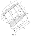
- Each of the surface sections 50a-c has longitudinally spaced front and rear ends, e.g., see the front and rear ends 50a', 50a" of the surface section 50a in Fig. 2, and corresponding front and rear ends 50b', 50b", 50c', 50c" of the other surface sections 50b, 50c.
- the surface sections 50a-50c are neither cylindrical nor conical. Rather, they are configured wherein a portion of each surface section situated between its front and rear ends is spaced farther from the axis 48 than are the front and rear ends of such surface section.
- the distances d1 and d2 which represent the respective distances of the front and rear ends 50c', 50c" from the axis, are equal to one another and shorter by an amount X than the distance d3 between the axis and the surface section 50c at a location between (interjacent) the front and rear ends.
- that relationship is achieved by making each of the surface sections 50a-50c of spherical curvature as indicated by the radius r for the surface section 50a in Fig. 6.
- the distance X is preferably about 0.0005 inches.
- the curvatures of the spherical surface sections 50a-c are shown somewhat exaggeratedly in the drawings.
- the radius r for each of the surface sections could be about 391 inches.
- Shapes for the surface sections other than spherical are possible, such as elliptical or parabolic for example.
- the mouth 52 of the hole 46 is slightly chamfered as can be seen in Fig. 6 in order to facilitate the insertion of a hollow sleeve 60 which is adapted to receive a cutter bit, such as a rotatable bit of the type shown in Fig. 1 and which is retained by any suitable conventional retainer.
- the bit can be suitable for cutting asphalt, concrete, dirt, rock, etc.
- the hollow sleeve 60 includes an enlarged head 62 and a shank 64 extending rearwardly therefrom along a longitudinal center axis 66 of the sleeve.
- a flange 68 is formed, i.e., a flange which extends substantially perpendicularly to the axis 66, in order to abut the block and terminate the insertion of the shank 64 into the hole 46.
- flange 68 is optional. Instead, there could be provided an abutment on the block that is engaged by a rear end of the shank to terminate the insertion.
- the shank 64 includes an outer periphery having a radially stepped configuration that substantially conforms to that of the hole 46. That is, the outer surface of the shank includes a plurality of axially adjacent sections 70a, 70b, 70c that become successively smaller in cross-section in a direction away from the flange 68 and which create an interference fit with the hole.
- the cross-sectional shape of the surface sections 70a-70c of the shank could be slightly larger than the corresponding cross-sectional shape of the surface section of the hole 46 to achieve an interference fit preferably in the range of .003-.004 inches.
- a cross-section taken through the shank 64 could be of circular configuration, as can be seen in Fig. 5.
- each surface section 70a-70c has longitudinally spaced front and rear ends, wherein a portion of each surface section 70a-70c situated between the front and rear ends thereof is spaced farther from the axis 66 than are the front and rear ends of the surface section.
- each surface section is spaced farther from the radius than are the ends of the surface section, e.g., by 0.0005 inches. That means that as the surface sections 70a, 70b, 70c enter their respective surface sections 50a, 50b, 50c, there occurs a deformation of the shank and/or the hole surface by 0.0005 inches in addition to the deformation necessary to produce the interference fit of .003-.004 inches. Once the surfaces have mated, the material of the block and/or shank will snap back by 0.0005 inches due to the inherent resiliency thereof, thereby providing an indication that the mating has occurred, as well as providing an extra retaining force for holding the sleeve within the hole 46.
- the overall surface area of the spherical surface sections 70a-70c and 50a-70c is greater than if those surfaces were cylindrically or conically shaped.
- the extra surface area provides added resistance to rotation of the sleeve once the sleeve has been installed.
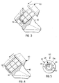
- the rear end of the shank 64 is provided with an external annular recess 80 which will project slightly from the rear end of the hole once the sleeve has been fully installed, as can be seen in Fig. 4. That annular recess is shaped to receive a retainer, such as a split C-shaped ring clip 82 which will bear against a rear side 84 of the block 42 in a manner imparting a rearward force (i.e., leftward force in Fig. 4), to further retain the sleeve within the hole.
- a retainer such as a split C-shaped ring clip 82 which will bear against a rear side 84 of the block 42 in a manner imparting a rearward force (i.e., leftward force in Fig. 4), to further retain the sleeve within the hole.
- That split ring clip 82 could be curved in the manner of a Belleville washer in order to provide a rearward bias to the sleeve, or the split ring 82 could be flat and a separate O-ring could be provided within the recess 80, between the split ring 82 and a rearward-most side of the recess 80 in order to bias the sleeve in a rearward (leftward) direction.
- the internal surface 90 of the sleeve (see Fig. 5) is shaped to receive a conventional cutter bit (not shown) possibly of the type shown in Fig. 1.
- Fig. 3 Depicted in Fig. 3 is a state of the shank during an initial stage of insertion into the hole 46, i.e., when initial resistance is first encountered. That is, the surfaces 70a, 70b, 70c of the sleeve have made initial contact with the surfaces 50a, 50b, 50c, respectively, of the hole. In order to facilitate the insertion of the shank, it is common to provide lubricating oil on the shank. It will be appreciated that when the initial contact is made, small closed spaces 92 are formed between surface sections of the shank and surface sections of the hole. As the shank is forced farther into the hole, oil which is trapped in those spaces will become pressurized and oppose rearward movement of the shank.
- grooves 94 are formed in the outer periphery of the shank which extend in a front-to-rear direction, preferably parallel to the axis 66.
- the grooves could extend helically along the shank.
- Three such grooves 94 are depicted in the drawings at 120 degrees apart, but any suitable number of grooves could be employed.
- Those grooves 94 serve as discharge passages for pressurized oil, which will relieve any force that the oil would otherwise have tended to impart to the sleeve.
- the slots are shown in a somewhat exaggerated state in the figures.
- a suitable groove could have a width in the circumferential direction of at least 0.010 inches, and a depth of at least 0.005 inches.
- the distance difference X is eliminated as the surfaces snap-back, thereby leaving the interference fit of .003-.004 inches.
- the additional deformation of X must re-occur.
- the sleeve is very reliably held in place.
- the lubricating oil which has been applied to the shank to facilitate installation thereof will be free to flow out of the hole along the groove or grooves 94, rather than being pressurized in a manner opposing a full installation of the sleeve.
- the present invention provides a more effective interference fit of the shank within the hole to more effectively resist premature longitudinal dislodgement of the sleeve, as well as to resist rotation of the sleeve within the hole.
- the sleeve 60 is securely held in place due to the provision of three surface sections i.e., the front, rear, and intermediate surface sections 50a, 50c, 50b, respectively as compared to the two surface sections provided in the prior art.
- the longitudinal length L of each surface section is substantially equal to the longitudinal distance L' from the front end 50a' of the front surface section 50a to the rear end 50c" of the rear surface section 50c.
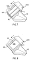
- Such an expedient may not even require the need for a separate sleeve fastener 82, as demonstrated by the arrangement shown in Fig. 8 wherein the shank of the sleeve 60B is inserted into a blind hole 90, rather than into a through-hole.
- Such an arrangement might be best used in a system where there is insufficient room at the back of the block 42B to provide a fastener 82.
- the concave/convex relationships could be reversed, as noted earlier. That is, the shank of the sleeve could be concave, and the surface of the receiving hole 50A or 90 would be convex.
- the sleeve could have a flange or collar C that engages the holder block to limit the extent of insertion into the hole, as shown in Figs. 7 and 8.
Landscapes
- Engineering & Computer Science (AREA)
- Mining & Mineral Resources (AREA)
- Mechanical Engineering (AREA)
- Life Sciences & Earth Sciences (AREA)
- General Life Sciences & Earth Sciences (AREA)
- Geochemistry & Mineralogy (AREA)
- Geology (AREA)
- Drilling And Exploitation, And Mining Machines And Methods (AREA)
- Drilling Tools (AREA)
- Gripping On Spindles (AREA)
- Wire Bonding (AREA)
- Processing Of Stones Or Stones Resemblance Materials (AREA)
Priority Applications (1)
| Application Number | Priority Date | Filing Date | Title |
|---|---|---|---|
| EP08104288A EP1956187B1 (fr) | 2005-02-18 | 2006-02-14 | Bloc porte-outil et manchon retenu dans celui-ci par ajustage serré |
Applications Claiming Priority (1)
| Application Number | Priority Date | Filing Date | Title |
|---|---|---|---|
| US11/061,551 US7234782B2 (en) | 2005-02-18 | 2005-02-18 | Tool holder block and sleeve retained therein by interference fit |
Related Child Applications (1)
| Application Number | Title | Priority Date | Filing Date |
|---|---|---|---|
| EP08104288A Division EP1956187B1 (fr) | 2005-02-18 | 2006-02-14 | Bloc porte-outil et manchon retenu dans celui-ci par ajustage serré |
Publications (3)
| Publication Number | Publication Date |
|---|---|
| EP1703077A2 true EP1703077A2 (fr) | 2006-09-20 |
| EP1703077A3 EP1703077A3 (fr) | 2006-11-29 |
| EP1703077B1 EP1703077B1 (fr) | 2008-09-17 |
Family
ID=36141825
Family Applications (2)
| Application Number | Title | Priority Date | Filing Date |
|---|---|---|---|
| EP06101668A Expired - Lifetime EP1703077B1 (fr) | 2005-02-18 | 2006-02-14 | Bloc porte-outil et manchon retenu dans celui-ci par ajustage serré |
| EP08104288A Expired - Lifetime EP1956187B1 (fr) | 2005-02-18 | 2006-02-14 | Bloc porte-outil et manchon retenu dans celui-ci par ajustage serré |
Family Applications After (1)
| Application Number | Title | Priority Date | Filing Date |
|---|---|---|---|
| EP08104288A Expired - Lifetime EP1956187B1 (fr) | 2005-02-18 | 2006-02-14 | Bloc porte-outil et manchon retenu dans celui-ci par ajustage serré |
Country Status (10)
| Country | Link |
|---|---|
| US (2) | US7234782B2 (fr) |
| EP (2) | EP1703077B1 (fr) |
| CN (1) | CN1828015B (fr) |
| AT (2) | ATE553283T1 (fr) |
| AU (1) | AU2006200642B9 (fr) |
| CA (1) | CA2535598C (fr) |
| DE (1) | DE602006002761D1 (fr) |
| GB (1) | GB2423319B (fr) |
| MX (1) | MXPA06001935A (fr) |
| NO (1) | NO20060765L (fr) |
Cited By (1)
| Publication number | Priority date | Publication date | Assignee | Title |
|---|---|---|---|---|
| CN105666093A (zh) * | 2016-03-23 | 2016-06-15 | 宁波拓普工业自动化有限公司 | 一种轴与深孔过盈配合的装配方法 |
Families Citing this family (100)
| Publication number | Priority date | Publication date | Assignee | Title |
|---|---|---|---|---|
| US8190877B2 (en) * | 2005-07-05 | 2012-05-29 | Viasat, Inc. | Trusted cryptographic processor |
| USD585259S1 (en) * | 2006-03-10 | 2009-01-27 | Wirtgen Bmbh | Chisel holder |
| USD574689S1 (en) * | 2006-03-10 | 2008-08-12 | Wirtgen Gmbh | Chisel holder |
| USD575610S1 (en) * | 2006-03-10 | 2008-08-26 | Wirtgen Gmbh | Chisel holder |
| DE102006029300B3 (de) * | 2006-06-23 | 2007-11-29 | Betek Bergbau- Und Hartmetalltechnik Karl-Heinz Simon Gmbh & Co. Kg | Rundschaftmeißel |
| US8590644B2 (en) | 2006-08-11 | 2013-11-26 | Schlumberger Technology Corporation | Downhole drill bit |
| US8485609B2 (en) * | 2006-08-11 | 2013-07-16 | Schlumberger Technology Corporation | Impact tool |
| US9051795B2 (en) | 2006-08-11 | 2015-06-09 | Schlumberger Technology Corporation | Downhole drill bit |
| US8123302B2 (en) | 2006-08-11 | 2012-02-28 | Schlumberger Technology Corporation | Impact tool |
| US8215420B2 (en) | 2006-08-11 | 2012-07-10 | Schlumberger Technology Corporation | Thermally stable pointed diamond with increased impact resistance |
| US8449040B2 (en) | 2006-08-11 | 2013-05-28 | David R. Hall | Shank for an attack tool |
| US8500210B2 (en) * | 2006-08-11 | 2013-08-06 | Schlumberger Technology Corporation | Resilient pick shank |
| US8414085B2 (en) * | 2006-08-11 | 2013-04-09 | Schlumberger Technology Corporation | Shank assembly with a tensioned element |
| US8007051B2 (en) | 2006-08-11 | 2011-08-30 | Schlumberger Technology Corporation | Shank assembly |
| US7413258B2 (en) * | 2006-08-11 | 2008-08-19 | Hall David R | Hollow pick shank |
| US8292372B2 (en) | 2007-12-21 | 2012-10-23 | Hall David R | Retention for holder shank |
| US8622155B2 (en) | 2006-08-11 | 2014-01-07 | Schlumberger Technology Corporation | Pointed diamond working ends on a shear bit |
| US8201892B2 (en) | 2006-08-11 | 2012-06-19 | Hall David R | Holder assembly |
| US8567532B2 (en) | 2006-08-11 | 2013-10-29 | Schlumberger Technology Corporation | Cutting element attached to downhole fixed bladed bit at a positive rake angle |
| US7871133B2 (en) | 2006-08-11 | 2011-01-18 | Schlumberger Technology Corporation | Locking fixture |
| US8033616B2 (en) | 2006-08-11 | 2011-10-11 | Schlumberger Technology Corporation | Braze thickness control |
| US9145742B2 (en) | 2006-08-11 | 2015-09-29 | Schlumberger Technology Corporation | Pointed working ends on a drill bit |
| US7669674B2 (en) | 2006-08-11 | 2010-03-02 | Hall David R | Degradation assembly |
| US7946657B2 (en) | 2006-08-11 | 2011-05-24 | Schlumberger Technology Corporation | Retention for an insert |
| US7637574B2 (en) | 2006-08-11 | 2009-12-29 | Hall David R | Pick assembly |
| US8714285B2 (en) | 2006-08-11 | 2014-05-06 | Schlumberger Technology Corporation | Method for drilling with a fixed bladed bit |
| US8960337B2 (en) | 2006-10-26 | 2015-02-24 | Schlumberger Technology Corporation | High impact resistant tool with an apex width between a first and second transitions |
| US9068410B2 (en) | 2006-10-26 | 2015-06-30 | Schlumberger Technology Corporation | Dense diamond body |
| US9051794B2 (en) | 2007-04-12 | 2015-06-09 | Schlumberger Technology Corporation | High impact shearing element |
| US7926883B2 (en) | 2007-05-15 | 2011-04-19 | Schlumberger Technology Corporation | Spring loaded pick |
| CA2639118A1 (fr) * | 2007-09-04 | 2009-03-04 | Kenneth Monyak | Manchon de retenue hybride pour outil insere dans un bloc |
| CA2706967A1 (fr) * | 2007-12-05 | 2009-06-11 | Sandvik Intellectual Property Ab | Outil de fragmentation ou d'excavation pourvu d'une piece rapportee en carbure de tungstene cemente et d'une bague, machine d'evacuation de materiau equipee dudit outil et procedede fabrication dudit outil |
| US8646848B2 (en) * | 2007-12-21 | 2014-02-11 | David R. Hall | Resilient connection between a pick shank and block |
| US8746702B1 (en) * | 2008-02-25 | 2014-06-10 | Ajax Tool Works, Inc. | Impact hammer tool bit retainer incorporating shielding ring |
| US8540037B2 (en) | 2008-04-30 | 2013-09-24 | Schlumberger Technology Corporation | Layered polycrystalline diamond |
| US8657385B2 (en) | 2008-05-20 | 2014-02-25 | Sandvik Intellectual Property Ab | Carbide block and sleeve wear surface |
| US8061783B2 (en) * | 2008-08-14 | 2011-11-22 | Kennametal Inc. | Bit holder block with non-rotating wear sleeve |
| US7883154B2 (en) * | 2008-08-28 | 2011-02-08 | Kennametal Inc. | Cutting tool with water injection to the cutting bit shank |
| US8540320B2 (en) * | 2009-04-02 | 2013-09-24 | The Sollami Company | Slotted shank bit holder |
| US8322796B2 (en) | 2009-04-16 | 2012-12-04 | Schlumberger Technology Corporation | Seal with contact element for pick shield |
| US8701799B2 (en) | 2009-04-29 | 2014-04-22 | Schlumberger Technology Corporation | Drill bit cutter pocket restitution |
| US8727357B2 (en) * | 2009-11-25 | 2014-05-20 | Kennametal Inc. | Toolholder secondary retention system |
| JP5793507B2 (ja) | 2010-01-07 | 2015-10-14 | ジーケーエヌ シンター メタルズ、エル・エル・シー | 工作機械及び該工作機械の製造方法 |
| US10385689B1 (en) | 2010-08-27 | 2019-08-20 | The Sollami Company | Bit holder |
| US10072501B2 (en) | 2010-08-27 | 2018-09-11 | The Sollami Company | Bit holder |
| US10598013B2 (en) | 2010-08-27 | 2020-03-24 | The Sollami Company | Bit holder with shortened nose portion |
| US10337324B2 (en) | 2015-01-07 | 2019-07-02 | The Sollami Company | Various bit holders and unitary bit/holders for use with shortened depth bit holder blocks |
| US9879531B2 (en) * | 2014-02-26 | 2018-01-30 | The Sollami Company | Bit holder shank and differential interference between the shank distal portion and the bit holder block bore |
| US11261731B1 (en) | 2014-04-23 | 2022-03-01 | The Sollami Company | Bit holder and unitary bit/holder for use in shortened depth base blocks |
| US8740314B2 (en) * | 2011-01-11 | 2014-06-03 | Joy Mm Delaware, Inc. | Bit holding system with an opening for removal of broken bits |
| US9757730B2 (en) | 2011-07-06 | 2017-09-12 | Joy Mm Delaware, Inc. | Pick retainer |
| DE102011054384A1 (de) * | 2011-10-11 | 2013-04-11 | Betek Gmbh & Co. Kg | Meißelhalter |
| RU2476672C1 (ru) * | 2011-11-10 | 2013-02-27 | Николай Митрофанович Панин | Резец для горных машин |
| RU2458224C1 (ru) * | 2011-11-10 | 2012-08-10 | Николай Митрофанович Панин | Резец для горных машин |
| US20130169022A1 (en) | 2011-12-28 | 2013-07-04 | Sandvik Intellectual Property Ab | Radial and conical tools with compression band retainer |
| SE538940C2 (sv) * | 2012-05-30 | 2017-02-28 | Combi Wear Parts Ab | Verktyg och verktygshållare för mudderverk |
| USD681069S1 (en) * | 2012-07-31 | 2013-04-30 | Caterpillar Paving Products Inc. | Mounting block for paving apparatus |
| USD680560S1 (en) * | 2012-07-31 | 2013-04-23 | Caterpillar Paving Products Inc. | Deflector for paving apparatus |
| US10260342B1 (en) | 2012-10-19 | 2019-04-16 | The Sollami Company | Combination polycrystalline diamond bit and bit holder |
| US9909416B1 (en) | 2013-09-18 | 2018-03-06 | The Sollami Company | Diamond tipped unitary holder/bit |
| US10323515B1 (en) | 2012-10-19 | 2019-06-18 | The Sollami Company | Tool with steel sleeve member |
| US9988903B2 (en) | 2012-10-19 | 2018-06-05 | The Sollami Company | Combination polycrystalline diamond bit and bit holder |
| US10180065B1 (en) | 2015-10-05 | 2019-01-15 | The Sollami Company | Material removing tool for road milling mining and trenching operations |
| US10107097B1 (en) | 2012-10-19 | 2018-10-23 | The Sollami Company | Combination polycrystalline diamond bit and bit holder |
| US10105870B1 (en) | 2012-10-19 | 2018-10-23 | The Sollami Company | Combination polycrystalline diamond bit and bit holder |
| US9724701B2 (en) | 2013-03-12 | 2017-08-08 | Joy Mm Delaware, Inc. | Tapered pick holder |
| US10794181B2 (en) | 2014-04-02 | 2020-10-06 | The Sollami Company | Bit/holder with enlarged ballistic tip insert |
| US10995613B1 (en) | 2013-09-18 | 2021-05-04 | The Sollami Company | Diamond tipped unitary holder/bit |
| US10876402B2 (en) | 2014-04-02 | 2020-12-29 | The Sollami Company | Bit tip insert |
| US10767478B2 (en) | 2013-09-18 | 2020-09-08 | The Sollami Company | Diamond tipped unitary holder/bit |
| US10577931B2 (en) | 2016-03-05 | 2020-03-03 | The Sollami Company | Bit holder (pick) with shortened shank and angular differential between the shank and base block bore |
| US9976418B2 (en) | 2014-04-02 | 2018-05-22 | The Sollami Company | Bit/holder with enlarged ballistic tip insert |
| US10968739B1 (en) | 2013-09-18 | 2021-04-06 | The Sollami Company | Diamond tipped unitary holder/bit |
| US10415386B1 (en) | 2013-09-18 | 2019-09-17 | The Sollami Company | Insertion-removal tool for holder/bit |
| US10947844B1 (en) | 2013-09-18 | 2021-03-16 | The Sollami Company | Diamond Tipped Unitary Holder/Bit |
| US10633971B2 (en) | 2016-03-07 | 2020-04-28 | The Sollami Company | Bit holder with enlarged tire portion and narrowed bit holder block |
| US11168563B1 (en) | 2013-10-16 | 2021-11-09 | The Sollami Company | Bit holder with differential interference |
| US9212553B2 (en) | 2013-11-08 | 2015-12-15 | The Sollami Company | Dirt and rock cutting bit tool |
| US11339656B1 (en) | 2014-02-26 | 2022-05-24 | The Sollami Company | Rear of base block |
| CN103850652B (zh) * | 2014-03-27 | 2015-11-18 | 湖南易通矿山工程机械有限公司 | 一种凿岩钻头合金齿镶嵌工艺 |
| US11339654B2 (en) | 2014-04-02 | 2022-05-24 | The Sollami Company | Insert with heat transfer bore |
| US11891895B1 (en) | 2014-04-23 | 2024-02-06 | The Sollami Company | Bit holder with annular rings |
| GB2545618B (en) * | 2014-09-15 | 2020-04-29 | Joy Global Underground Mining Llc | Service tool for cutting bit assembly |
| US9422812B2 (en) | 2014-10-14 | 2016-08-23 | Kennametal Inc. | Cutting tool mounting assembly with elastomeric coated bushing |
| WO2016141898A1 (fr) * | 2015-03-12 | 2016-09-15 | 刘素华 | Procédé permettant à une base de dent à trou traversant d'assembler et désassembler rapidement une dent d'impact à mouvement alternatif, et dispositif d'impact dans lequel une base de dent à trou traversant assemble et désassemble rapidement une dent d'impact à mouvement alternatif |
| US10502056B2 (en) | 2015-09-30 | 2019-12-10 | The Sollami Company | Reverse taper shanks and complementary base block bores for bit assemblies |
| US10107098B2 (en) | 2016-03-15 | 2018-10-23 | The Sollami Company | Bore wear compensating bit holder and bit holder block |
| US10612376B1 (en) | 2016-03-15 | 2020-04-07 | The Sollami Company | Bore wear compensating retainer and washer |
| US10612375B2 (en) | 2016-04-01 | 2020-04-07 | The Sollami Company | Bit retainer |
| US10876401B1 (en) | 2016-07-26 | 2020-12-29 | The Sollami Company | Rotational style tool bit assembly |
| US10968738B1 (en) | 2017-03-24 | 2021-04-06 | The Sollami Company | Remanufactured conical bit |
| US11187080B2 (en) | 2018-04-24 | 2021-11-30 | The Sollami Company | Conical bit with diamond insert |
| US11279012B1 (en) | 2017-09-15 | 2022-03-22 | The Sollami Company | Retainer insertion and extraction tool |
| US11103939B2 (en) | 2018-07-18 | 2021-08-31 | The Sollami Company | Rotatable bit cartridge |
| US12345158B1 (en) | 2019-06-20 | 2025-07-01 | The Sollami Company | Bit tip insert |
| CN110410074B (zh) * | 2019-08-19 | 2024-05-03 | 天地科技股份有限公司上海分公司 | 抱紧装置和掘进机伸缩机构 |
| US12421995B2 (en) | 2022-09-16 | 2025-09-23 | Pratt & Whitney Canada Corp. | Propeller shaft with reinforced front flange |
| US12448998B2 (en) * | 2022-09-16 | 2025-10-21 | Pratt & Whitney Canada Corp. | Propeller shaft assembly for aircraft engine |
| US12535099B2 (en) | 2022-09-16 | 2026-01-27 | Pratt & Whitney Canada Corp. | Propeller shaft with reinforced front flange |
| CN115822588B (zh) * | 2022-12-01 | 2026-03-10 | 山东科技大学 | 一种自动化精准截割悬臂掘进机及截割方法 |
Citations (5)
| Publication number | Priority date | Publication date | Assignee | Title |
|---|---|---|---|---|
| US4247150A (en) | 1978-06-15 | 1981-01-27 | Voest-Alpine Aktiengesellschaft | Bit arrangement for a cutting tool |
| GB2071184A (en) | 1980-03-05 | 1981-09-16 | Hollingworth K J | Coal cutter pick boxes |
| US5106166A (en) | 1990-09-07 | 1992-04-21 | Joy Technologies Inc. | Cutting bit holding apparatus |
| US5302005A (en) | 1990-09-07 | 1994-04-12 | Joy Technologies Inc. | Apparatus for holding a cutting bit |
| US5725283A (en) | 1996-04-16 | 1998-03-10 | Joy Mm Delaware, Inc. | Apparatus for holding a cutting bit |
Family Cites Families (44)
| Publication number | Priority date | Publication date | Assignee | Title |
|---|---|---|---|---|
| US3143177A (en) | 1961-01-23 | 1964-08-04 | Louis C Galorneau | Tool holder |
| US3397012A (en) | 1966-12-19 | 1968-08-13 | Cincinnati Mine Machinery Co | Cutter bits and means for mounting them |
| US3499685A (en) | 1968-08-08 | 1970-03-10 | Kennametal Inc | Pick-type mining bit with support block having rotatable seat |
| GB1218308A (en) | 1969-08-11 | 1971-01-06 | Kennametal Inc | Mining tool |
| US3749190A (en) | 1971-05-06 | 1973-07-31 | Ingersoll Rand Co | Retaining carbide in rock drill bits |
| US3941495A (en) | 1975-03-14 | 1976-03-02 | Lane Duncan | Ball and socket joint and method of making the same |
| US4685381A (en) * | 1978-05-31 | 1987-08-11 | Karl Eickmann | Pivot portion of a piston shoe in fluid machines |
| US4201421A (en) | 1978-09-20 | 1980-05-06 | Besten Leroy E Den | Mining machine bit and mounting thereof |
| DE2854307A1 (de) | 1978-12-15 | 1980-07-03 | Kennametal Inc | Halter zur anbringung von meisseln, insbesondere von rundschaftmeisseln an bergbaulichen gewinnungs- und streckenvortriebsmaschinen |
| US4337980A (en) * | 1979-05-21 | 1982-07-06 | The Cincinnati Mine Machinery Company | Wedge arrangements and related means for mounting means, base members, and bits, and combinations thereof, for mining, road working, or earth moving machinery |
| US4247147A (en) | 1979-11-21 | 1981-01-27 | Sandvik Aktiebolag | Retainer clip for cutter bits |
| US4299424A (en) | 1979-12-03 | 1981-11-10 | National Mine Service Company | Cutting tool assembly |
| AT369859B (de) | 1981-03-12 | 1983-02-10 | Voest Alpine Ag | Einrichtung zum kuehlen der meissel einer schraemmaschine |
| AT375149B (de) | 1982-07-06 | 1984-07-10 | Voest Alpine Ag | Mit einer spruehvorrichtung ausgestatteter meisselhalter |
| DE3242137C2 (de) * | 1982-11-13 | 1985-06-05 | Ruhrkohle Ag, 4300 Essen | Gedämpft geführter Rundschaftmeißel |
| DE3307910A1 (de) | 1983-03-05 | 1984-09-27 | Fried. Krupp Gmbh, 4300 Essen | Werkzeuganordnung mit einem rundschaftmeissel |
| US4470210A (en) * | 1983-05-25 | 1984-09-11 | Esco Corporation | Mounting for excavating implement and method |
| GB8333339D0 (en) | 1983-12-14 | 1984-01-18 | Hall & Pickles Ltd | Mineral cutter pick and box |
| US4575156A (en) | 1984-03-13 | 1986-03-11 | Fansteel Inc. | Mining block and bit |
| US4684176A (en) | 1984-05-16 | 1987-08-04 | Den Besten Leroy E | Cutter bit device |
| US4632463A (en) | 1984-08-03 | 1986-12-30 | The Cincinnati Mine Machinery Company | Combined base member and bit holder with protected retainer |
| JPS6295395A (ja) * | 1985-10-21 | 1987-05-01 | Buaioretsuto:Kk | 潤滑油用添加剤 |
| US4836614A (en) | 1985-11-21 | 1989-06-06 | Gte Products Corporation | Retainer scheme for machine bit |
| DE3630443A1 (de) | 1986-09-06 | 1988-03-10 | Worley & Partner Gmbh | Vorrichtung zur schneidenden gewinnung/abtragung von materialien |
| US4850649A (en) | 1986-10-07 | 1989-07-25 | Kennametal Inc. | Rotatable cutting bit |
| US4728153A (en) | 1986-12-22 | 1988-03-01 | Gte Products Corporation | Cylindrical retainer for a cutting bit |
| SE461165B (sv) | 1987-06-12 | 1990-01-15 | Hans Olav Norman | Verktyg foer brytning, avverkning eller bearbetning av fasta material |
| US5067775A (en) | 1988-04-21 | 1991-11-26 | Kennametal Inc. | Retainer for rotatable bits |
| US4875532A (en) | 1988-09-19 | 1989-10-24 | Dresser Industries, Inc. | Roller drill bit having radial-thrust pilot bushing incorporating anti-galling material |
| DE3911893A1 (de) * | 1989-04-12 | 1990-10-18 | Paurat Gmbh | Vorrichtung fuer die schneidmeisselhalterung am schneidkopf einer vortriebsmaschine |
| GB2273513B (en) | 1992-12-04 | 1996-04-24 | Hydra Tools Int Plc | Mineral cutter tooling system |
| GB9400114D0 (en) | 1994-01-05 | 1994-03-02 | Minnovation Ltd | Mineral pick box |
| US5685381A (en) | 1995-07-21 | 1997-11-11 | Kennametal South Africa (Proprietary) Limited | Drill rod and drill bit with rocking connection |
| US5607206A (en) | 1995-08-02 | 1997-03-04 | Kennametal Inc. | Cutting tool holder retention system |
| AT406503B (de) * | 1995-12-21 | 2000-06-26 | Voest Alpine Bergtechnik | Meisselanordnung für einen rundschaftmeissel |
| US6176552B1 (en) | 1998-10-05 | 2001-01-23 | Kennametal Inc. | Cutting bit support member with undercut flange for removal |
| US6113195A (en) | 1998-10-08 | 2000-09-05 | Sandvik Ab | Rotatable cutting bit and bit washer therefor |
| UA73489C2 (en) | 1998-12-08 | 2005-08-15 | Genisis Mining Technologies Pr | Cutting arrangement and sleeve for it |
| PL187208B1 (pl) | 1999-01-25 | 2004-06-30 | Boart Longyear Gmbh & Co Kg | Zespół noża obrotowego zwłaszcza do maszyn górniczych |
| USD422127S (en) * | 1999-03-02 | 2000-03-28 | Ipl Inc. | Barrel |
| US6371567B1 (en) | 1999-03-22 | 2002-04-16 | The Sollami Company | Bit holders and bit blocks for road milling, mining and trenching equipment |
| USD448909S1 (en) * | 2000-06-06 | 2001-10-02 | Irene Friesen | Barrel |
| US6786557B2 (en) | 2000-12-20 | 2004-09-07 | Kennametal Inc. | Protective wear sleeve having tapered lock and retainer |
| US6854810B2 (en) | 2000-12-20 | 2005-02-15 | Kennametal Inc. | T-shaped cutter tool assembly with wear sleeve |
-
2005
- 2005-02-18 US US11/061,551 patent/US7234782B2/en not_active Expired - Fee Related
-
2006
- 2006-02-08 CA CA2535598A patent/CA2535598C/fr not_active Expired - Fee Related
- 2006-02-14 GB GB0602972A patent/GB2423319B/en not_active Expired - Fee Related
- 2006-02-14 AT AT08104288T patent/ATE553283T1/de active
- 2006-02-14 EP EP06101668A patent/EP1703077B1/fr not_active Expired - Lifetime
- 2006-02-14 AT AT06101668T patent/ATE408748T1/de not_active IP Right Cessation
- 2006-02-14 EP EP08104288A patent/EP1956187B1/fr not_active Expired - Lifetime
- 2006-02-14 DE DE602006002761T patent/DE602006002761D1/de not_active Expired - Lifetime
- 2006-02-16 AU AU2006200642A patent/AU2006200642B9/en not_active Ceased
- 2006-02-17 MX MXPA06001935A patent/MXPA06001935A/es active IP Right Grant
- 2006-02-17 NO NO20060765A patent/NO20060765L/no not_active Application Discontinuation
- 2006-02-20 CN CN2006100041454A patent/CN1828015B/zh not_active Expired - Fee Related
- 2006-09-22 US US11/525,089 patent/US7270379B2/en not_active Expired - Fee Related
Patent Citations (5)
| Publication number | Priority date | Publication date | Assignee | Title |
|---|---|---|---|---|
| US4247150A (en) | 1978-06-15 | 1981-01-27 | Voest-Alpine Aktiengesellschaft | Bit arrangement for a cutting tool |
| GB2071184A (en) | 1980-03-05 | 1981-09-16 | Hollingworth K J | Coal cutter pick boxes |
| US5106166A (en) | 1990-09-07 | 1992-04-21 | Joy Technologies Inc. | Cutting bit holding apparatus |
| US5302005A (en) | 1990-09-07 | 1994-04-12 | Joy Technologies Inc. | Apparatus for holding a cutting bit |
| US5725283A (en) | 1996-04-16 | 1998-03-10 | Joy Mm Delaware, Inc. | Apparatus for holding a cutting bit |
Cited By (1)
| Publication number | Priority date | Publication date | Assignee | Title |
|---|---|---|---|---|
| CN105666093A (zh) * | 2016-03-23 | 2016-06-15 | 宁波拓普工业自动化有限公司 | 一种轴与深孔过盈配合的装配方法 |
Also Published As
| Publication number | Publication date |
|---|---|
| EP1703077A3 (fr) | 2006-11-29 |
| US20070013224A1 (en) | 2007-01-18 |
| AU2006200642A1 (en) | 2006-09-07 |
| US20060186724A1 (en) | 2006-08-24 |
| ATE408748T1 (de) | 2008-10-15 |
| MXPA06001935A (es) | 2007-04-17 |
| EP1956187B1 (fr) | 2012-04-11 |
| CN1828015B (zh) | 2011-02-09 |
| US7234782B2 (en) | 2007-06-26 |
| EP1956187A2 (fr) | 2008-08-13 |
| ATE553283T1 (de) | 2012-04-15 |
| AU2006200642B2 (en) | 2011-02-17 |
| EP1956187A3 (fr) | 2010-02-17 |
| NO20060765L (no) | 2006-08-21 |
| DE602006002761D1 (de) | 2008-10-30 |
| GB2423319B (en) | 2010-05-05 |
| GB0602972D0 (en) | 2006-03-29 |
| AU2006200642B9 (en) | 2011-07-14 |
| US7270379B2 (en) | 2007-09-18 |
| CA2535598A1 (fr) | 2006-08-18 |
| GB2423319A (en) | 2006-08-23 |
| EP1703077B1 (fr) | 2008-09-17 |
| CN1828015A (zh) | 2006-09-06 |
| CA2535598C (fr) | 2012-04-24 |
Similar Documents
| Publication | Publication Date | Title |
|---|---|---|
| US7234782B2 (en) | Tool holder block and sleeve retained therein by interference fit | |
| US5725283A (en) | Apparatus for holding a cutting bit | |
| US4084856A (en) | Self-retaining sleeve and bit | |
| AU2008207567B2 (en) | Hybrid retainer sleeve for tool inserted into block | |
| AU747606B2 (en) | Rotatable cutting bit and bit washer therefor | |
| US5503463A (en) | Retainer scheme for cutting tool | |
| US5628549A (en) | Cutting tool sleeve rotation limitation system | |
| US4850649A (en) | Rotatable cutting bit | |
| US4327947A (en) | Keeper spring for connecting mining tool to work tool holder | |
| US9702251B2 (en) | Cutting tool assembly including retainer sleeve with retention member | |
| US8506019B2 (en) | Block and sleeve with rotation-inhibiting feature | |
| US20110233987A1 (en) | Rotatable Cutting Tool And Tool Holder Assembly | |
| EP0264015B1 (fr) | Mèche de coupe rotative | |
| EP2313612B1 (fr) | Dispositif de retenue de manchon complet et demi-manche d'outil | |
| GB2428709A (en) | Retainer sleeve for a rotary bit |
Legal Events
| Date | Code | Title | Description |
|---|---|---|---|
| PUAI | Public reference made under article 153(3) epc to a published international application that has entered the european phase |
Free format text: ORIGINAL CODE: 0009012 |
|
| AK | Designated contracting states |
Kind code of ref document: A2 Designated state(s): AT BE BG CH CY CZ DE DK EE ES FI FR GB GR HU IE IS IT LI LT LU LV MC NL PL PT RO SE SI SK TR |
|
| AX | Request for extension of the european patent |
Extension state: AL BA HR MK YU |
|
| PUAL | Search report despatched |
Free format text: ORIGINAL CODE: 0009013 |
|
| AK | Designated contracting states |
Kind code of ref document: A3 Designated state(s): AT BE BG CH CY CZ DE DK EE ES FI FR GB GR HU IE IS IT LI LT LU LV MC NL PL PT RO SE SI SK TR |
|
| AX | Request for extension of the european patent |
Extension state: AL BA HR MK YU |
|
| 17P | Request for examination filed |
Effective date: 20070427 |
|
| 17Q | First examination report despatched |
Effective date: 20070604 |
|
| AKX | Designation fees paid |
Designated state(s): AT BE BG CH CY CZ DE DK EE ES FI FR GB GR HU IE IS IT LI LT LU LV MC NL PL PT RO SE SI SK TR |
|
| GRAP | Despatch of communication of intention to grant a patent |
Free format text: ORIGINAL CODE: EPIDOSNIGR1 |
|
| GRAS | Grant fee paid |
Free format text: ORIGINAL CODE: EPIDOSNIGR3 |
|
| GRAA | (expected) grant |
Free format text: ORIGINAL CODE: 0009210 |
|
| AK | Designated contracting states |
Kind code of ref document: B1 Designated state(s): AT BE BG CH CY CZ DE DK EE ES FI FR GB GR HU IE IS IT LI LT LU LV MC NL PL PT RO SE SI SK TR |
|
| REG | Reference to a national code |
Ref country code: GB Ref legal event code: FG4D |
|
| REG | Reference to a national code |
Ref country code: CH Ref legal event code: EP |
|
| REG | Reference to a national code |
Ref country code: IE Ref legal event code: FG4D |
|
| REF | Corresponds to: |
Ref document number: 602006002761 Country of ref document: DE Date of ref document: 20081030 Kind code of ref document: P |
|
| RIN2 | Information on inventor provided after grant (corrected) |
Inventor name: STEHNEY, STEPHEN C. |
|
| REG | Reference to a national code |
Ref country code: SE Ref legal event code: TRGR |
|
| PG25 | Lapsed in a contracting state [announced via postgrant information from national office to epo] |
Ref country code: LT Free format text: LAPSE BECAUSE OF FAILURE TO SUBMIT A TRANSLATION OF THE DESCRIPTION OR TO PAY THE FEE WITHIN THE PRESCRIBED TIME-LIMIT Effective date: 20080917 |
|
| PG25 | Lapsed in a contracting state [announced via postgrant information from national office to epo] |
Ref country code: LV Free format text: LAPSE BECAUSE OF FAILURE TO SUBMIT A TRANSLATION OF THE DESCRIPTION OR TO PAY THE FEE WITHIN THE PRESCRIBED TIME-LIMIT Effective date: 20080917 Ref country code: SI Free format text: LAPSE BECAUSE OF FAILURE TO SUBMIT A TRANSLATION OF THE DESCRIPTION OR TO PAY THE FEE WITHIN THE PRESCRIBED TIME-LIMIT Effective date: 20080917 Ref country code: FI Free format text: LAPSE BECAUSE OF FAILURE TO SUBMIT A TRANSLATION OF THE DESCRIPTION OR TO PAY THE FEE WITHIN THE PRESCRIBED TIME-LIMIT Effective date: 20080917 Ref country code: AT Free format text: LAPSE BECAUSE OF FAILURE TO SUBMIT A TRANSLATION OF THE DESCRIPTION OR TO PAY THE FEE WITHIN THE PRESCRIBED TIME-LIMIT Effective date: 20080917 |
|
| NLV1 | Nl: lapsed or annulled due to failure to fulfill the requirements of art. 29p and 29m of the patents act | ||
| PG25 | Lapsed in a contracting state [announced via postgrant information from national office to epo] |
Ref country code: BE Free format text: LAPSE BECAUSE OF FAILURE TO SUBMIT A TRANSLATION OF THE DESCRIPTION OR TO PAY THE FEE WITHIN THE PRESCRIBED TIME-LIMIT Effective date: 20080917 |
|
| PG25 | Lapsed in a contracting state [announced via postgrant information from national office to epo] |
Ref country code: BG Free format text: LAPSE BECAUSE OF FAILURE TO SUBMIT A TRANSLATION OF THE DESCRIPTION OR TO PAY THE FEE WITHIN THE PRESCRIBED TIME-LIMIT Effective date: 20081217 Ref country code: ES Free format text: LAPSE BECAUSE OF FAILURE TO SUBMIT A TRANSLATION OF THE DESCRIPTION OR TO PAY THE FEE WITHIN THE PRESCRIBED TIME-LIMIT Effective date: 20081228 |
|
| PG25 | Lapsed in a contracting state [announced via postgrant information from national office to epo] |
Ref country code: IS Free format text: LAPSE BECAUSE OF FAILURE TO SUBMIT A TRANSLATION OF THE DESCRIPTION OR TO PAY THE FEE WITHIN THE PRESCRIBED TIME-LIMIT Effective date: 20090117 Ref country code: PT Free format text: LAPSE BECAUSE OF FAILURE TO SUBMIT A TRANSLATION OF THE DESCRIPTION OR TO PAY THE FEE WITHIN THE PRESCRIBED TIME-LIMIT Effective date: 20090217 Ref country code: RO Free format text: LAPSE BECAUSE OF FAILURE TO SUBMIT A TRANSLATION OF THE DESCRIPTION OR TO PAY THE FEE WITHIN THE PRESCRIBED TIME-LIMIT Effective date: 20080917 Ref country code: SK Free format text: LAPSE BECAUSE OF FAILURE TO SUBMIT A TRANSLATION OF THE DESCRIPTION OR TO PAY THE FEE WITHIN THE PRESCRIBED TIME-LIMIT Effective date: 20080917 Ref country code: NL Free format text: LAPSE BECAUSE OF FAILURE TO SUBMIT A TRANSLATION OF THE DESCRIPTION OR TO PAY THE FEE WITHIN THE PRESCRIBED TIME-LIMIT Effective date: 20080917 Ref country code: CZ Free format text: LAPSE BECAUSE OF FAILURE TO SUBMIT A TRANSLATION OF THE DESCRIPTION OR TO PAY THE FEE WITHIN THE PRESCRIBED TIME-LIMIT Effective date: 20080917 |
|
| PLBE | No opposition filed within time limit |
Free format text: ORIGINAL CODE: 0009261 |
|
| STAA | Information on the status of an ep patent application or granted ep patent |
Free format text: STATUS: NO OPPOSITION FILED WITHIN TIME LIMIT |
|
| PG25 | Lapsed in a contracting state [announced via postgrant information from national office to epo] |
Ref country code: DK Free format text: LAPSE BECAUSE OF FAILURE TO SUBMIT A TRANSLATION OF THE DESCRIPTION OR TO PAY THE FEE WITHIN THE PRESCRIBED TIME-LIMIT Effective date: 20080917 Ref country code: EE Free format text: LAPSE BECAUSE OF FAILURE TO SUBMIT A TRANSLATION OF THE DESCRIPTION OR TO PAY THE FEE WITHIN THE PRESCRIBED TIME-LIMIT Effective date: 20080917 |
|
| 26N | No opposition filed |
Effective date: 20090618 |
|
| PG25 | Lapsed in a contracting state [announced via postgrant information from national office to epo] |
Ref country code: MC Free format text: LAPSE BECAUSE OF NON-PAYMENT OF DUE FEES Effective date: 20090228 |
|
| REG | Reference to a national code |
Ref country code: IE Ref legal event code: MM4A |
|
| PG25 | Lapsed in a contracting state [announced via postgrant information from national office to epo] |
Ref country code: IE Free format text: LAPSE BECAUSE OF NON-PAYMENT OF DUE FEES Effective date: 20090214 |
|
| PG25 | Lapsed in a contracting state [announced via postgrant information from national office to epo] |
Ref country code: PL Free format text: LAPSE BECAUSE OF FAILURE TO SUBMIT A TRANSLATION OF THE DESCRIPTION OR TO PAY THE FEE WITHIN THE PRESCRIBED TIME-LIMIT Effective date: 20080917 |
|
| REG | Reference to a national code |
Ref country code: CH Ref legal event code: PL |
|
| GBPC | Gb: european patent ceased through non-payment of renewal fee |
Effective date: 20100214 |
|
| PG25 | Lapsed in a contracting state [announced via postgrant information from national office to epo] |
Ref country code: LI Free format text: LAPSE BECAUSE OF NON-PAYMENT OF DUE FEES Effective date: 20100228 Ref country code: GR Free format text: LAPSE BECAUSE OF FAILURE TO SUBMIT A TRANSLATION OF THE DESCRIPTION OR TO PAY THE FEE WITHIN THE PRESCRIBED TIME-LIMIT Effective date: 20081218 Ref country code: CH Free format text: LAPSE BECAUSE OF NON-PAYMENT OF DUE FEES Effective date: 20100228 |
|
| PG25 | Lapsed in a contracting state [announced via postgrant information from national office to epo] |
Ref country code: GB Free format text: LAPSE BECAUSE OF NON-PAYMENT OF DUE FEES Effective date: 20100214 |
|
| PG25 | Lapsed in a contracting state [announced via postgrant information from national office to epo] |
Ref country code: LU Free format text: LAPSE BECAUSE OF NON-PAYMENT OF DUE FEES Effective date: 20090214 |
|
| PG25 | Lapsed in a contracting state [announced via postgrant information from national office to epo] |
Ref country code: HU Free format text: LAPSE BECAUSE OF FAILURE TO SUBMIT A TRANSLATION OF THE DESCRIPTION OR TO PAY THE FEE WITHIN THE PRESCRIBED TIME-LIMIT Effective date: 20090318 |
|
| PG25 | Lapsed in a contracting state [announced via postgrant information from national office to epo] |
Ref country code: TR Free format text: LAPSE BECAUSE OF FAILURE TO SUBMIT A TRANSLATION OF THE DESCRIPTION OR TO PAY THE FEE WITHIN THE PRESCRIBED TIME-LIMIT Effective date: 20080917 |
|
| PG25 | Lapsed in a contracting state [announced via postgrant information from national office to epo] |
Ref country code: CY Free format text: LAPSE BECAUSE OF FAILURE TO SUBMIT A TRANSLATION OF THE DESCRIPTION OR TO PAY THE FEE WITHIN THE PRESCRIBED TIME-LIMIT Effective date: 20080917 |
|
| PGFP | Annual fee paid to national office [announced via postgrant information from national office to epo] |
Ref country code: FR Payment date: 20120306 Year of fee payment: 7 |
|
| PGFP | Annual fee paid to national office [announced via postgrant information from national office to epo] |
Ref country code: DE Payment date: 20120228 Year of fee payment: 7 |
|
| PGFP | Annual fee paid to national office [announced via postgrant information from national office to epo] |
Ref country code: IT Payment date: 20120223 Year of fee payment: 7 Ref country code: SE Payment date: 20120228 Year of fee payment: 7 |
|
| REG | Reference to a national code |
Ref country code: SE Ref legal event code: EUG |
|
| PG25 | Lapsed in a contracting state [announced via postgrant information from national office to epo] |
Ref country code: SE Free format text: LAPSE BECAUSE OF NON-PAYMENT OF DUE FEES Effective date: 20130215 |
|
| REG | Reference to a national code |
Ref country code: FR Ref legal event code: ST Effective date: 20131031 |
|
| REG | Reference to a national code |
Ref country code: DE Ref legal event code: R119 Ref document number: 602006002761 Country of ref document: DE Effective date: 20130903 |
|
| PG25 | Lapsed in a contracting state [announced via postgrant information from national office to epo] |
Ref country code: IT Free format text: LAPSE BECAUSE OF NON-PAYMENT OF DUE FEES Effective date: 20130214 |
|
| PG25 | Lapsed in a contracting state [announced via postgrant information from national office to epo] |
Ref country code: FR Free format text: LAPSE BECAUSE OF NON-PAYMENT OF DUE FEES Effective date: 20130228 Ref country code: DE Free format text: LAPSE BECAUSE OF NON-PAYMENT OF DUE FEES Effective date: 20130903 |