EP1703090A2 - Entlüftungssystem für Hydraulikkreis - Google Patents
Entlüftungssystem für Hydraulikkreis Download PDFInfo
- Publication number
- EP1703090A2 EP1703090A2 EP06004914A EP06004914A EP1703090A2 EP 1703090 A2 EP1703090 A2 EP 1703090A2 EP 06004914 A EP06004914 A EP 06004914A EP 06004914 A EP06004914 A EP 06004914A EP 1703090 A2 EP1703090 A2 EP 1703090A2
- Authority
- EP
- European Patent Office
- Prior art keywords
- solenoid
- relief valve
- assembly
- control channel
- energized
- Prior art date
- Legal status (The legal status is an assumption and is not a legal conclusion. Google has not performed a legal analysis and makes no representation as to the accuracy of the status listed.)
- Withdrawn
Links
- 239000012530 fluid Substances 0.000 claims abstract description 35
- 230000000712 assembly Effects 0.000 description 3
- 238000000429 assembly Methods 0.000 description 3
- 238000010586 diagram Methods 0.000 description 3
- 230000000740 bleeding effect Effects 0.000 description 2
- 230000001934 delay Effects 0.000 description 2
- 230000004048 modification Effects 0.000 description 2
- 238000012986 modification Methods 0.000 description 2
- 230000003213 activating effect Effects 0.000 description 1
- 238000006073 displacement reaction Methods 0.000 description 1
Images

Classifications
-
- F—MECHANICAL ENGINEERING; LIGHTING; HEATING; WEAPONS; BLASTING
- F16—ENGINEERING ELEMENTS AND UNITS; GENERAL MEASURES FOR PRODUCING AND MAINTAINING EFFECTIVE FUNCTIONING OF MACHINES OR INSTALLATIONS; THERMAL INSULATION IN GENERAL
- F16K—VALVES; TAPS; COCKS; ACTUATING-FLOATS; DEVICES FOR VENTING OR AERATING
- F16K31/00—Actuating devices; Operating means; Releasing devices
- F16K31/02—Actuating devices; Operating means; Releasing devices electric; magnetic
- F16K31/06—Actuating devices; Operating means; Releasing devices electric; magnetic using a magnet, e.g. diaphragm valves, cutting off by means of a liquid
- F16K31/0644—One-way valve
- F16K31/0655—Lift valves
- F16K31/0665—Lift valves with valve member being at least partially ball-shaped
-
- F—MECHANICAL ENGINEERING; LIGHTING; HEATING; WEAPONS; BLASTING
- F01—MACHINES OR ENGINES IN GENERAL; ENGINE PLANTS IN GENERAL; STEAM ENGINES
- F01L—CYCLICALLY OPERATING VALVES FOR MACHINES OR ENGINES
- F01L13/00—Modifications of valve-gear to facilitate reversing, braking, starting, changing compression ratio, or other specific operations
- F01L13/0005—Deactivating valves
-
- F—MECHANICAL ENGINEERING; LIGHTING; HEATING; WEAPONS; BLASTING
- F01—MACHINES OR ENGINES IN GENERAL; ENGINE PLANTS IN GENERAL; STEAM ENGINES
- F01L—CYCLICALLY OPERATING VALVES FOR MACHINES OR ENGINES
- F01L9/00—Valve-gear or valve arrangements actuated non-mechanically
- F01L9/10—Valve-gear or valve arrangements actuated non-mechanically by fluid means, e.g. hydraulic
-
- F—MECHANICAL ENGINEERING; LIGHTING; HEATING; WEAPONS; BLASTING
- F01—MACHINES OR ENGINES IN GENERAL; ENGINE PLANTS IN GENERAL; STEAM ENGINES
- F01L—CYCLICALLY OPERATING VALVES FOR MACHINES OR ENGINES
- F01L1/00—Valve-gear or valve arrangements, e.g. lift-valve gear
- F01L1/20—Adjusting or compensating clearance
- F01L1/22—Adjusting or compensating clearance automatically, e.g. mechanically
- F01L1/24—Adjusting or compensating clearance automatically, e.g. mechanically by fluid means, e.g. hydraulically
- F01L2001/2444—Details relating to the hydraulic feeding circuit, e.g. lifter oil manifold assembly [LOMA]
Definitions
- the present invention relates to manifold assemblies that control fluid circulation in an automobile engine, and more particularly to a hydraulic circuit configuration for bleeding air out of a lifter oil manifold assembly.
- Lifter oil manifold assemblies are hydraulic circuits generally known in the art and used in conjunction with Displacement on Demand (DoD) engines.
- the hydraulic circuit routes fluid pressure to solenoid control valves.
- the solenoids When commanded by a powertrain control computer, the solenoids direct fluid to valve lifters equipped with a switching mechanism.
- the solenoids themselves are used as electro-mechanical devices or hydraulic switches to control fluid supplied to a control circuit when a particular solenoid is energized.
- the control circuit activates or deactivates a given valve lifter switch by controlling a control pressure applied to the switch; if the control pressure is high, for example, the valve lifter switch is turned on to operate the valve lifter.
- the present invention is directed to a manifold assembly that includes an orifice that connects an inlet circuit directly to a control circuit in the assembly. This direct connection between the inlet circuit and the control circuit via the orifice allows air to be bled out of the manifold assembly quickly. When the vehicle engine is turned on, the orifice allows low pressure fluid in the assembly to push fluid and any trapped air through the orifice and control circuit out of the assembly.
- Figure 1 is a perspective cutaway view of a portion of a manifold assembly according to one embodiment of the invention
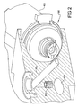
- Figure 2 is another perspective cutaway view of a portion of the inventive manifold assembly
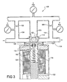
- Figure 3 is a representative diagram of an engine cylinder in the manifold assembly when the engine is turned off;
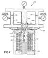
- Figure 4 is a representative diagram of the engine cylinder when the engine is turned on and the solenoid is turned off;
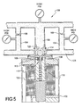
- Figure 5 is a representative diagram of the engine cylinder when the engine is turned on and the solenoid is energized.
- Figures 1 and 2 are cutaway views of a portion of a manifold assembly 100 to be used as a hydraulic circuit for an engine cylinder.
- the assembly 100 has a solenoid 102 that acts as a hydraulic switch to control fluid pressure through control ports to a lifter mechanical pressure switch (not shown).
- the assembly 100 includes one or more manifold control channels 104 fluidically coupled to the solenoid 102.
- Currently known assemblies 100 connect two control channels 104 to each solenoid 102. Fluid, such as oil, is directed into the control channel 104 via a manifold inlet port 105.
- An orifice 106 is connected between the inlet port 105 and the control channel 104 to provide a path for bleeding air out of the assembly 100.
- the orifice 106 connects the inlet port 106 directly to the control channel 104 rather than routing near the solenoid 102. This direction connection ensure that any air trapped within the orifice 106 or elsewhere in the assembly 100 can quickly leave the assembly 100 within a specified time period to ensure rapid system response.
- the assembly includes an exhaust port 108 through which air and fluid can flow out of the control channels 104 to a sump (e.g., an oil pan).
- the solenoid 102 includes a relief valve 110, such as a poppet valve, that allows air to escape from the assembly 100.
- the relief valve 110 includes a poppet spring 112 that changes the position of a poppet 114 to open or close the exhaust port 108.
- the solenoid 102 also includes an armature 118 with an armature spring 120 to move a ball valve 122 that opens and closes the inlet port 105. The ball therefore controls the pressure of fluid in the control channels 104.
- control channels 104 are fluidically coupled to control ports 124 that communicate with valve lifters (not shown).
- operation of the relief valve 110 and the ball valve 122 in the solenoid 102 controls the fluid flow and fluid pressure in the control channels 104 and control ports 124, thereby controlling operation of the valve lifters.
- Figure 3 illustrates the assembly 100 when the engine is turned off. At this stage, there is no inlet pressure in the inlet port 105 and no control pressure in the control channels 104.
- the poppet spring 112 in the relief valve 110 of the solenoid 102 is extended to close the exhaust port 108 from the control port 124.
- the armature spring 120 is extended to push the ball valve 122 against the inlet port 105. At this point, there is no fluid pressure in the inlet port 105 and control channels 104, and therefore no fluid pressure in the control ports 124.
- Figure 4 illustrates the assembly 100 when the engine is turned on and the solenoid 102 is turned off (i.e., de-energized). At this point, the armature spring 120 continues to push the ball valve 122 against the inlet port 105 to keep it closed, preventing fluid from flowing through the inlet into the control channels 104 as long as the solenoid is de-energized.
- the orifice 106 allows the fluid in the control channels 104 to reach a limited, low fluid pressure that is not high enough to activate the valve lifters.
- the orifice 106 is sized to allow the fluid pressure in the orifice 106, and consequently the control channels 104, to reach a level that is high enough to compress the poppet spring 112; the biasing force in the poppet spring 112 is weak enough so that even low fluid pressure in the control channels 104 is enough to open the relief valve 110.
- any air trapped in the control channels 104 flows through the control channels 104, past the open relief valve 110 and out the exhaust ports 108.
- the orifice 106 size also controls the flow rate of fluid out of the exhaust ports 108.
- arranging the orifice 106 to form a direct fluid path between the inlet port 105 with the control channel 104 ensures that this exhaust flow is quick and reliable.
- energizing the solenoid 102 will cause the fluid pressure in the control channels 104 to reach full operational pressure quickly and easily, without undesirable delays in system response. More particularly, as shown in Figure 5, energizing the solenoid 102 causes the armature spring 120 to shift, pulling the ball valve 122 away from the inlet port 105 to allow the fluid to flow into the control channels 104 and equalize the fluid pressure in the control channels 104 and the inlet port 105. At the same time, the ball valve 122 seals the exhaust ports 108, preventing fluid from flowing out into the sump. As a result, the fluid pressure in the control channels 104, and thus the control ports 124, is high enough to activate the valve lifters.
- the inventive structure By providing a direct pressure feed orifice from the inlet circuit directly to the control circuit of the manifold assembly, the inventive structure reduces the time needed to bleed any trapped air out of the assembly. It also eliminates the risk of residual air from remaining in the system, which often occurs when the orifice is placed in a solenoid pocket instead of directly connected to the control circuit. This direction connect ensures that the control circuit will reach full system pressure quickly when the solenoid is energized without experiencing unacceptable response delays.
Landscapes
- Engineering & Computer Science (AREA)
- General Engineering & Computer Science (AREA)
- Mechanical Engineering (AREA)
- Magnetically Actuated Valves (AREA)
- Fluid-Pressure Circuits (AREA)
Applications Claiming Priority (1)
| Application Number | Priority Date | Filing Date | Title |
|---|---|---|---|
| US11/082,480 US7174866B2 (en) | 2005-03-17 | 2005-03-17 | Direct pressure feed air bleed system |
Publications (2)
| Publication Number | Publication Date |
|---|---|
| EP1703090A2 true EP1703090A2 (de) | 2006-09-20 |
| EP1703090A3 EP1703090A3 (de) | 2009-07-29 |
Family
ID=36648329
Family Applications (1)
| Application Number | Title | Priority Date | Filing Date |
|---|---|---|---|
| EP06004914A Withdrawn EP1703090A3 (de) | 2005-03-17 | 2006-03-10 | Entlüftungssystem für Hydraulikkreis |
Country Status (2)
| Country | Link |
|---|---|
| US (1) | US7174866B2 (de) |
| EP (1) | EP1703090A3 (de) |
Cited By (1)
| Publication number | Priority date | Publication date | Assignee | Title |
|---|---|---|---|---|
| CN106471226A (zh) * | 2014-07-03 | 2017-03-01 | 优尼克株式会社 | 油泵控制阀 |
Families Citing this family (3)
| Publication number | Priority date | Publication date | Assignee | Title |
|---|---|---|---|---|
| US10544710B2 (en) | 2015-03-23 | 2020-01-28 | Ford Global Technologies, Llc | Hydraulic circuit for valve deactivation |
| US9650922B2 (en) | 2015-04-28 | 2017-05-16 | Ford Global Technologies, Llc | External oil groove on a hydraulic lash adjuster |
| US9765656B2 (en) | 2015-06-15 | 2017-09-19 | Ford Global Technologies, Llc | Hydraulic circuit for valve deactivation |
Citations (1)
| Publication number | Priority date | Publication date | Assignee | Title |
|---|---|---|---|---|
| US20040079307A1 (en) | 2002-10-25 | 2004-04-29 | Dinkel Michael J. | Apparatus for purging and excluding air from a hydraulic manifold assembly for variable deactivation of engine valves |
Family Cites Families (20)
| Publication number | Priority date | Publication date | Assignee | Title |
|---|---|---|---|---|
| WO1999010671A1 (en) * | 1997-08-25 | 1999-03-04 | Mitsubishi Denki Kabushiki Kaisha | Solenoid valve |
| DE19810241C2 (de) * | 1998-03-10 | 2001-07-05 | Bosch Gmbh Robert | Elektromagnetisches Wegeventil |
| US6786186B2 (en) * | 1998-09-09 | 2004-09-07 | International Engine Intellectual Property Company, Llc | Unit trigger actuator |
| GB2348245B (en) * | 1999-03-25 | 2002-10-23 | Ricardo Inc | Valvegear for engines of reciprocating piston type |
| DE19937969A1 (de) * | 1999-08-11 | 2001-02-15 | Hydraulik Ring Gmbh | Hydraulisches Ventil, insbesondere verstellbares Druckregelventil |
| US6481409B1 (en) * | 2000-03-30 | 2002-11-19 | Fasco Controls, Inc. | Electro-hydraulic control module for deactivating intake and exhaust valves |
| DE10034959A1 (de) * | 2000-07-19 | 2002-02-21 | Zahnradfabrik Friedrichshafen | Proportional-Druckregelventil |
| US6439176B1 (en) * | 2001-03-05 | 2002-08-27 | Delphi Technologies, Inc. | Control system for deactivation of valves in an internal combustion engine |
| ITTO20010273A1 (it) * | 2001-03-23 | 2002-09-23 | Fiat Ricerche | Motore a combustione interna con sistema idraulico per l'azionamento variabile delle valvole e con mezzi di spurgo dell'aria dal sistema idr |
| US6817325B2 (en) * | 2001-11-13 | 2004-11-16 | Delphi Technologies, Inc. | Hydraulic manifold assembly for variable activation and deactivation of valves in an internal combustion engine |
| US6591796B1 (en) * | 2002-02-21 | 2003-07-15 | Delphi Technologies, Inc. | Combination PCV baffle and retainer for solenoid valves in a hydraulic manifold assembly for variable activation and deactivation of engine valves |
| US6644265B2 (en) * | 2002-04-09 | 2003-11-11 | Eaton Corporation | Electro-hydraulic manifold assembly and method of making same for controlling de-activation of combustion chamber valves in a multicylinder engine |
| US6584942B1 (en) * | 2002-05-29 | 2003-07-01 | General Motors Corporation | Cylinder deactivation apparatus with vapor purge |
| ITTO20020571A1 (it) * | 2002-07-01 | 2004-01-02 | Fiat Ricerche | Motore a combustione interna con due valvole di aspirazione per ciascun cilindro e sistema a controllo elettronico per azionare le due valvo |
| ITTO20020569A1 (it) * | 2002-07-01 | 2004-01-02 | Fiat Ricerche | Motore a combustione interna con sistema idraulico a controllo elettronico per l'azionamento delle valvole di aspirazione, con mezzi di comp |
| ITTO20020568A1 (it) * | 2002-07-01 | 2004-01-02 | Fiat Ricerche | Motore a combustione interna con sistema idraulico a controllo elettronico per l'azionamento delle valvole e mezzi per compensare i cambiame |
| US6666178B1 (en) * | 2002-08-08 | 2003-12-23 | Eaton Corporation | Valve deactivation with an electro-hydraulic actuator |
| US6782852B2 (en) * | 2002-10-07 | 2004-08-31 | Husco International, Inc. | Hydraulic actuator for operating an engine cylinder valve |
| DE10252431A1 (de) * | 2002-11-12 | 2004-05-27 | Ina-Schaeffler Kg | Elektromagnetisches Hydraulikventil, insbesondere 3/2-Wegeschaltventil zur Steuerung eines variablen Ventiltriebes einer Brennkraftmaschine |
| US7007641B1 (en) * | 2004-12-22 | 2006-03-07 | Eaton Corporation | Electro-hydraulic assembly for controlling engine valve deactivation |
-
2005
- 2005-03-17 US US11/082,480 patent/US7174866B2/en not_active Expired - Fee Related
-
2006
- 2006-03-10 EP EP06004914A patent/EP1703090A3/de not_active Withdrawn
Patent Citations (1)
| Publication number | Priority date | Publication date | Assignee | Title |
|---|---|---|---|---|
| US20040079307A1 (en) | 2002-10-25 | 2004-04-29 | Dinkel Michael J. | Apparatus for purging and excluding air from a hydraulic manifold assembly for variable deactivation of engine valves |
Cited By (2)
| Publication number | Priority date | Publication date | Assignee | Title |
|---|---|---|---|---|
| CN106471226A (zh) * | 2014-07-03 | 2017-03-01 | 优尼克株式会社 | 油泵控制阀 |
| CN106471226B (zh) * | 2014-07-03 | 2019-09-06 | 优尼克株式会社 | 油泵控制阀 |
Also Published As
| Publication number | Publication date |
|---|---|
| US7174866B2 (en) | 2007-02-13 |
| US20060207530A1 (en) | 2006-09-21 |
| EP1703090A3 (de) | 2009-07-29 |
Similar Documents
| Publication | Publication Date | Title |
|---|---|---|
| KR101538198B1 (ko) | 오일 제어 밸브 및 오일 유동 제어 방법 | |
| US8157076B2 (en) | Hydraulic control for a park by wire system used in a multimode hybrid transmission | |
| US20020029811A1 (en) | Pneumatic volume booster for valve positioner | |
| CN112292298A (zh) | 用于机动车的驻车制动装置 | |
| JP2006528110A (ja) | 自動車用ブレーキシステム | |
| JPH08261204A (ja) | 油圧モータの駆動装置 | |
| CN100334360C (zh) | 低能量消耗的电磁阀 | |
| EP1703090A2 (de) | Entlüftungssystem für Hydraulikkreis | |
| US8857313B2 (en) | Fluid operated actuator system | |
| US9939061B2 (en) | Hydraulic control apparatus | |
| CN112292296A (zh) | 用于机动车的驻车制动设备 | |
| KR20120064037A (ko) | 자동차 자동 트랜스미션용 슬라이드 밸브 | |
| US5119717A (en) | Method of controlling solenoid valves for a hydraulic actuator, with a time delay between closing a normally open valve and opening a normally closed valve | |
| CN101868633B (zh) | 在故障状态期间具有减小的出口压力的高通量双阀 | |
| US5117868A (en) | Pilot-controlled directional valve | |
| CN114829217B (zh) | 阀装置 | |
| KR100553657B1 (ko) | 전자석 밸브 장치 | |
| JP2008082540A (ja) | 油圧制御装置 | |
| JP2004263871A (ja) | 液圧式の制御弁 | |
| EP0578583A1 (de) | Hydraulisches Servoventil mit kontrollierter Abschaltung | |
| EP2689142B1 (de) | Ventil | |
| JP3861834B2 (ja) | 遮断器の流体圧駆動装置 | |
| JP3153466B2 (ja) | スロースタートバルブ | |
| KR960015253B1 (ko) | 변속기 조작용 액츄에이터의 제어장치 | |
| JP3001229B2 (ja) | リリーフ機能付き流体装置 |
Legal Events
| Date | Code | Title | Description |
|---|---|---|---|
| PUAI | Public reference made under article 153(3) epc to a published international application that has entered the european phase |
Free format text: ORIGINAL CODE: 0009012 |
|
| AK | Designated contracting states |
Kind code of ref document: A2 Designated state(s): AT BE BG CH CY CZ DE DK EE ES FI FR GB GR HU IE IS IT LI LT LU LV MC NL PL PT RO SE SI SK TR |
|
| AX | Request for extension of the european patent |
Extension state: AL BA HR MK YU |
|
| PUAL | Search report despatched |
Free format text: ORIGINAL CODE: 0009013 |
|
| AK | Designated contracting states |
Kind code of ref document: A3 Designated state(s): AT BE BG CH CY CZ DE DK EE ES FI FR GB GR HU IE IS IT LI LT LU LV MC NL PL PT RO SE SI SK TR |
|
| AX | Request for extension of the european patent |
Extension state: AL BA HR MK YU |
|
| 17P | Request for examination filed |
Effective date: 20090922 |
|
| 17Q | First examination report despatched |
Effective date: 20091028 |
|
| AKX | Designation fees paid |
Designated state(s): DE SE |
|
| R17C | First examination report despatched (corrected) |
Effective date: 20100429 |
|
| STAA | Information on the status of an ep patent application or granted ep patent |
Free format text: STATUS: THE APPLICATION IS DEEMED TO BE WITHDRAWN |
|
| 18D | Application deemed to be withdrawn |
Effective date: 20131001 |