EP1703094A2 - Système de lubrification pour moteur à combustion - Google Patents
Système de lubrification pour moteur à combustion Download PDFInfo
- Publication number
- EP1703094A2 EP1703094A2 EP05027772A EP05027772A EP1703094A2 EP 1703094 A2 EP1703094 A2 EP 1703094A2 EP 05027772 A EP05027772 A EP 05027772A EP 05027772 A EP05027772 A EP 05027772A EP 1703094 A2 EP1703094 A2 EP 1703094A2
- Authority
- EP
- European Patent Office
- Prior art keywords
- oil
- lubricating oil
- pump
- lubricating
- cooler
- Prior art date
- Legal status (The legal status is an assumption and is not a legal conclusion. Google has not performed a legal analysis and makes no representation as to the accuracy of the status listed.)
- Granted
Links
Images
Classifications
-
- F—MECHANICAL ENGINEERING; LIGHTING; HEATING; WEAPONS; BLASTING
- F01—MACHINES OR ENGINES IN GENERAL; ENGINE PLANTS IN GENERAL; STEAM ENGINES
- F01M—LUBRICATING OF MACHINES OR ENGINES IN GENERAL; LUBRICATING INTERNAL COMBUSTION ENGINES; CRANKCASE VENTILATING
- F01M1/00—Pressure lubrication
- F01M1/02—Pressure lubrication using lubricating pumps
-
- F—MECHANICAL ENGINEERING; LIGHTING; HEATING; WEAPONS; BLASTING
- F01—MACHINES OR ENGINES IN GENERAL; ENGINE PLANTS IN GENERAL; STEAM ENGINES
- F01M—LUBRICATING OF MACHINES OR ENGINES IN GENERAL; LUBRICATING INTERNAL COMBUSTION ENGINES; CRANKCASE VENTILATING
- F01M5/00—Heating, cooling, or controlling temperature of lubricant; Lubrication means facilitating engine starting
- F01M5/002—Cooling
-
- F—MECHANICAL ENGINEERING; LIGHTING; HEATING; WEAPONS; BLASTING
- F01—MACHINES OR ENGINES IN GENERAL; ENGINE PLANTS IN GENERAL; STEAM ENGINES
- F01M—LUBRICATING OF MACHINES OR ENGINES IN GENERAL; LUBRICATING INTERNAL COMBUSTION ENGINES; CRANKCASE VENTILATING
- F01M1/00—Pressure lubrication
- F01M1/12—Closed-circuit lubricating systems not provided for in groups F01M1/02 - F01M1/10
- F01M2001/123—Closed-circuit lubricating systems not provided for in groups F01M1/02 - F01M1/10 using two or more pumps
-
- F—MECHANICAL ENGINEERING; LIGHTING; HEATING; WEAPONS; BLASTING
- F01—MACHINES OR ENGINES IN GENERAL; ENGINE PLANTS IN GENERAL; STEAM ENGINES
- F01M—LUBRICATING OF MACHINES OR ENGINES IN GENERAL; LUBRICATING INTERNAL COMBUSTION ENGINES; CRANKCASE VENTILATING
- F01M11/00—Component parts, details or accessories, not provided for in, or of interest apart from, groups F01M1/00 - F01M9/00
- F01M11/0004—Oilsumps
- F01M2011/0037—Oilsumps with different oil compartments
Definitions
- the invention relates to a lubricating oil supply device for an internal combustion engine according to the features of the preamble of patent claim 1.
- the oil cooler is a hydraulic resistance, which leads in particular at low oil temperatures to a corresponding pressure drop.
- Downstream consumers e.g. hydraulically adjustable camshaft adjuster or a hydraulically actuated valve lift can be adversely affected due to insufficient oil pressure or amount of oil.
- the object of the invention is to avoid such disadvantages.
- the oil cooler is taken out as a significant hydraulic resistance from the main oil circuit and integrated into the second rear pump stage, the lubricating oil supply to consumers can be improved.
- the power consumption of the two oil pumps can be reduced in total, if the second pump stage, a lower oil flow rate is promoted, since then according to the hydraulic Resistance of the oil cooler is lower.
- the oil cooler is arranged on the pressure side of the second oil pump.
- the two oil pumps are summarized in an advantageous manner to a double oil pump with two pump stages.
- the oil conveyed back by the ATL oil suction pump into the first construction space section can also be cooled by the oil cooler in an advantageous manner.
- the pressure side of the ATL suction pump opens upstream of the oil cooler in the (secondary) lubricating oil circuit of the second oil pump (second pressure stage).
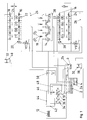
- the sole FIGURE shows a hydraulic circuit diagram of a supercharged dual-row eight-cylinder engine.
- a crankcase (not shown) of an internal combustion engine and only schematically illustrated oil collection housing, hereinafter referred to as sump 2 has a front and rear space section 2a and 2b, hereinafter referred to as the first and second oil collection space are designated.
- a suction pipe 4 and 6 is placed, which are connected on the suction side to each of an oil pump 8 and 10.
- the two oil pumps 8 and 10 are summarized as a double oil pump with two pump stages, the first pump stage 8 is adjustable.
- the lubricating oil collected in the rear oil collecting space 2b is pumped by means of the second pumping stage 10 into the first oil collecting space 2a.
- the rear lubricating oil circuit designed as a plate heat exchanger oil cooler 12 is integrated, which ensures appropriate cooling of the lubricating oil.
- the lubricating oil present in the first oil collecting space 2a is fed to the actual consumers of the internal combustion engine.
- These include: the main bearings of the crankshaft 14, the bearings for the four camshafts 16, the piston spray nozzles 18 (4x) and the hydraulically actuated camshaft adjuster 20 provided for both cylinder bank rows on the inlet side and switchable tappet 22 for valve lift switching (so-called Porsche VarioCamPlus system).
- the two cylinder heads supplied lubricating oil for the camshaft 16, the camshaft adjuster 20, the switchable tappets 22 and the valve clearance compensation elements 24 via first return channels 26 in the the first oil-collecting space 2a, while the lubricating oil provided for the main bearings of the crankshaft 14 and the piston-spraying nozzles 18 is returned to the rear oil-collecting space 2b via second oil-return passages 28.
- the exhaust gas turbocharger 30 and 32 provided for each cylinder bank row is likewise supplied with lubricating oil via the first pressure stage 8 for lubricating the drive.
- an oil-extraction pump 34 and 36 is provided which draws the lubricating oil from the so-called catch tank 38 and 40 and conveys it back into the first oil-collecting space 2a.
- the lubricating oil delivered by the two ATL extraction pumps 34 and 36 is also cooled accordingly via the oil cooler 12.
- a common pressure line 42 opens into the pressure line 44 of the second pump stage 10.
- a safety valve 46 is provided, which releases a corresponding bypass line 48, if necessary.
- a corresponding oil filter 50 is provided with a pressure relief valve.
Landscapes
- Engineering & Computer Science (AREA)
- Mechanical Engineering (AREA)
- General Engineering & Computer Science (AREA)
- Lubrication Of Internal Combustion Engines (AREA)
- Supercharger (AREA)
- Lubrication Details And Ventilation Of Internal Combustion Engines (AREA)
Applications Claiming Priority (1)
| Application Number | Priority Date | Filing Date | Title |
|---|---|---|---|
| DE102005012073A DE102005012073A1 (de) | 2005-03-16 | 2005-03-16 | Schmierölversorgungseinrichtung für eine Brennkraftmaschine |
Publications (3)
| Publication Number | Publication Date |
|---|---|
| EP1703094A2 true EP1703094A2 (fr) | 2006-09-20 |
| EP1703094A3 EP1703094A3 (fr) | 2010-03-24 |
| EP1703094B1 EP1703094B1 (fr) | 2011-11-23 |
Family
ID=36579873
Family Applications (1)
| Application Number | Title | Priority Date | Filing Date |
|---|---|---|---|
| EP05027772A Ceased EP1703094B1 (fr) | 2005-03-16 | 2005-12-19 | Système de lubrification pour moteur à combustion |
Country Status (4)
| Country | Link |
|---|---|
| US (1) | US20060207543A1 (fr) |
| EP (1) | EP1703094B1 (fr) |
| JP (1) | JP2006258099A (fr) |
| DE (1) | DE102005012073A1 (fr) |
Cited By (2)
| Publication number | Priority date | Publication date | Assignee | Title |
|---|---|---|---|---|
| CN103670580A (zh) * | 2013-11-29 | 2014-03-26 | 南车玉柴四川发动机股份有限公司 | 一种大功率柴油机的机油系统 |
| EP3351756A1 (fr) * | 2017-01-20 | 2018-07-25 | MAN Diesel & Turbo SE | Système d'alimentation en huile et son procédé de fonctionnement |
Families Citing this family (7)
| Publication number | Priority date | Publication date | Assignee | Title |
|---|---|---|---|---|
| DE102010022134A1 (de) * | 2010-05-20 | 2011-11-24 | Gm Global Technology Operations Llc (N.D.Ges.D. Staates Delaware) | Ölpumpenmodul mit einem Ölpumpenmodulgehäuse |
| US8408166B1 (en) | 2012-08-13 | 2013-04-02 | Ford Global Technologies, Llc | System with a heat pipe |
| DE102016104414B4 (de) * | 2016-03-10 | 2025-05-28 | Dr. Ing. H.C. F. Porsche Aktiengesellschaft | Ölversorgungssystem für einen Verbrennungsmotor sowie Verfahren zur Ölversorgung eines Verbrennungsmotors |
| US11719139B2 (en) * | 2016-10-31 | 2023-08-08 | Cummins Inc. | Reduced parasitic lube system |
| CN106837467A (zh) * | 2017-02-27 | 2017-06-13 | 安徽江淮汽车集团股份有限公司 | 一种发动机润滑系统 |
| CN107269342A (zh) * | 2017-06-21 | 2017-10-20 | 浙江春风动力股份有限公司 | 一种摩托车及v型双缸发动机润滑系统 |
| JP7089458B2 (ja) * | 2018-10-31 | 2022-06-22 | 株式会社クボタ | 過給機付きエンジン |
Citations (3)
| Publication number | Priority date | Publication date | Assignee | Title |
|---|---|---|---|---|
| GB237559A (en) | 1924-07-22 | 1925-10-29 | Renault Louis | Improvements in or relating to lubrication |
| DE4444276A1 (de) | 1994-12-13 | 1996-06-20 | Jenbacher Energiesysteme Ag | Anordnung zum Fördern und Kühlen des Schmieröls von Verbrennungsmotoren |
| DE10159106A1 (de) | 2001-12-01 | 2003-06-18 | Porsche Ag | Brennkraftmaschine |
Family Cites Families (11)
| Publication number | Priority date | Publication date | Assignee | Title |
|---|---|---|---|---|
| US4004634A (en) * | 1975-05-06 | 1977-01-25 | Universal Oil Products Company | Automotive oil cooler |
| JPS5822977Y2 (ja) * | 1977-06-24 | 1983-05-17 | 株式会社クボタ | 排気タ−ボ過給機付水冷エンジンの潤滑油冷却装置 |
| US4248293A (en) * | 1979-01-16 | 1981-02-03 | Honda Giken Kogyo Kabushiki Kaisha | Apparatus for cooling engine oil |
| JP2539260B2 (ja) * | 1988-12-03 | 1996-10-02 | マツダ株式会社 | Dohcエンジンのカム軸スラスト規制構造 |
| SE509078C2 (sv) * | 1993-10-13 | 1998-11-30 | Kvaerner Hymac Inc | Avbrottssäkrat smörjningssystem för en maskin |
| US5568842A (en) * | 1994-09-02 | 1996-10-29 | Otani; Akesama | Oil control unit for high-performance vehicles |
| JP3971082B2 (ja) * | 2000-05-11 | 2007-09-05 | 本田技研工業株式会社 | 内燃機関用潤滑装置 |
| US20030151030A1 (en) * | 2000-11-22 | 2003-08-14 | Gurin Michael H. | Enhanced conductivity nanocomposites and method of use thereof |
| DE10159090C2 (de) * | 2001-12-01 | 2003-09-11 | Porsche Ag | Ölauffangvorrichtung und Ölpumpe für eine Brennkraftmaschine |
| DE10159104B4 (de) * | 2001-12-01 | 2004-06-03 | Dr.Ing.H.C. F. Porsche Ag | Brennkraftmaschine |
| JP5020765B2 (ja) * | 2007-09-29 | 2012-09-05 | 本田技研工業株式会社 | 自動二輪車用パワーユニット |
-
2005
- 2005-03-16 DE DE102005012073A patent/DE102005012073A1/de not_active Withdrawn
- 2005-12-19 EP EP05027772A patent/EP1703094B1/fr not_active Ceased
-
2006
- 2006-02-22 US US11/357,970 patent/US20060207543A1/en not_active Abandoned
- 2006-03-15 JP JP2006070261A patent/JP2006258099A/ja active Pending
Patent Citations (3)
| Publication number | Priority date | Publication date | Assignee | Title |
|---|---|---|---|---|
| GB237559A (en) | 1924-07-22 | 1925-10-29 | Renault Louis | Improvements in or relating to lubrication |
| DE4444276A1 (de) | 1994-12-13 | 1996-06-20 | Jenbacher Energiesysteme Ag | Anordnung zum Fördern und Kühlen des Schmieröls von Verbrennungsmotoren |
| DE10159106A1 (de) | 2001-12-01 | 2003-06-18 | Porsche Ag | Brennkraftmaschine |
Cited By (3)
| Publication number | Priority date | Publication date | Assignee | Title |
|---|---|---|---|---|
| CN103670580A (zh) * | 2013-11-29 | 2014-03-26 | 南车玉柴四川发动机股份有限公司 | 一种大功率柴油机的机油系统 |
| CN103670580B (zh) * | 2013-11-29 | 2015-09-16 | 南车玉柴四川发动机股份有限公司 | 一种大功率柴油机的机油系统 |
| EP3351756A1 (fr) * | 2017-01-20 | 2018-07-25 | MAN Diesel & Turbo SE | Système d'alimentation en huile et son procédé de fonctionnement |
Also Published As
| Publication number | Publication date |
|---|---|
| EP1703094A3 (fr) | 2010-03-24 |
| DE102005012073A1 (de) | 2006-09-28 |
| JP2006258099A (ja) | 2006-09-28 |
| EP1703094B1 (fr) | 2011-11-23 |
| US20060207543A1 (en) | 2006-09-21 |
Similar Documents
| Publication | Publication Date | Title |
|---|---|---|
| DE69200153T2 (de) | Ölzufuhrsystem in einer Brennkraftmaschine. | |
| DE2720034C2 (de) | Schmiersystem | |
| DE102015109137A1 (de) | Ölkühlungssystem für aufgeladenen Verbrenner | |
| DE2950905A1 (de) | Kuehleinrichtung sowie zylinderkopf fuer verbrennungsmotor | |
| DE102013225464A1 (de) | Kühlmittelmantel für einen Turbolader-Ölablass | |
| EP1703094B1 (fr) | Système de lubrification pour moteur à combustion | |
| EP1761689B1 (fr) | Moteur a combustion interne a lubrification par circulation forcee selon le principe de la lubrification a carter sec | |
| EP1316685B1 (fr) | Moteur à combustion interne ayant un dispositif de lubrification d'un turbocompresseur | |
| EP1761687B1 (fr) | Moteur a combustion interne a lubrification par circulation forcee selon le principe de la lubrification a carter sec | |
| DE102004044998B4 (de) | Motorschmiersystem und druckverringerndes Ventil zur Begrenzung eines überschüssigen Öldurchflusses | |
| DE102010023063B4 (de) | Ölversorgungssystem für eine Brennkraftmaschine | |
| DE102010051761A1 (de) | Verfahren zum Abkühlen eines Hochdruckstössels | |
| DE10043795A1 (de) | Brennkraftmaschine mit Kurbelgehäuseentlüftung | |
| EP1280984A1 (fr) | Circuit de refroidissement pour moteur a combustion interne multicylindre | |
| DE102004044995B4 (de) | Ventile verwendendes Schmiersystem, um verschiedene Motoröldruckanforderungen zu erfüllen | |
| DE102005020959A1 (de) | Schmierölversorgungseinrichtung für eine Brennkraftmaschine | |
| DE3509095A1 (de) | Anordnung zur kuehlung und schmierung einer hubkolben-brennkraftmaschine | |
| WO2022197397A1 (fr) | Système de dérivation de filtre de fluide de lubrification | |
| DE102010005891A1 (de) | Mehrzylinderverbrennungsmotor | |
| EP1008733B1 (fr) | Culasse refroidie à l'huile | |
| WO2008046475A2 (fr) | Système de lubrification pour un moteur à combustion interne comprenant un turbocompresseur à gaz d'échappement | |
| DE102017106437B4 (de) | Frei positionierbares Kurbelgehäuse-Entlüftungssystem und Verfahren | |
| DE102010004875A1 (de) | Multi-Zylinder-Brennkraftmaschine | |
| DE102011015930A1 (de) | Kühleinrichtung einer Verbrennungskraftmaschine | |
| DE29709320U1 (de) | Aufgeladene Hubkolbenbrennkraftmaschine |
Legal Events
| Date | Code | Title | Description |
|---|---|---|---|
| PUAI | Public reference made under article 153(3) epc to a published international application that has entered the european phase |
Free format text: ORIGINAL CODE: 0009012 |
|
| AK | Designated contracting states |
Kind code of ref document: A2 Designated state(s): AT BE BG CH CY CZ DE DK EE ES FI FR GB GR HU IE IS IT LI LT LU LV MC NL PL PT RO SE SI SK TR |
|
| AX | Request for extension of the european patent |
Extension state: AL BA HR MK YU |
|
| RAP1 | Party data changed (applicant data changed or rights of an application transferred) |
Owner name: DR. ING. H.C. F. PORSCHE AKTIENGESELLSCHAFT |
|
| RAP1 | Party data changed (applicant data changed or rights of an application transferred) |
Owner name: DR. ING. H.C. F. PORSCHE AKTIENGESELLSCHAFT |
|
| PUAL | Search report despatched |
Free format text: ORIGINAL CODE: 0009013 |
|
| AK | Designated contracting states |
Kind code of ref document: A3 Designated state(s): AT BE BG CH CY CZ DE DK EE ES FI FR GB GR HU IE IS IT LI LT LU LV MC NL PL PT RO SE SI SK TR |
|
| AX | Request for extension of the european patent |
Extension state: AL BA HR MK YU |
|
| RAP1 | Party data changed (applicant data changed or rights of an application transferred) |
Owner name: DR. ING. H.C. F. PORSCHE AG |
|
| 17P | Request for examination filed |
Effective date: 20100924 |
|
| 17Q | First examination report despatched |
Effective date: 20101019 |
|
| AKX | Designation fees paid |
Designated state(s): DE FR GB IT SE |
|
| GRAP | Despatch of communication of intention to grant a patent |
Free format text: ORIGINAL CODE: EPIDOSNIGR1 |
|
| GRAS | Grant fee paid |
Free format text: ORIGINAL CODE: EPIDOSNIGR3 |
|
| GRAA | (expected) grant |
Free format text: ORIGINAL CODE: 0009210 |
|
| AK | Designated contracting states |
Kind code of ref document: B1 Designated state(s): DE FR GB IT SE |
|
| REG | Reference to a national code |
Ref country code: GB Ref legal event code: FG4D Free format text: NOT ENGLISH |
|
| REG | Reference to a national code |
Ref country code: DE Ref legal event code: R096 Ref document number: 502005012167 Country of ref document: DE Effective date: 20120223 |
|
| PG25 | Lapsed in a contracting state [announced via postgrant information from national office to epo] |
Ref country code: SE Free format text: LAPSE BECAUSE OF FAILURE TO SUBMIT A TRANSLATION OF THE DESCRIPTION OR TO PAY THE FEE WITHIN THE PRESCRIBED TIME-LIMIT Effective date: 20111123 |
|
| PG25 | Lapsed in a contracting state [announced via postgrant information from national office to epo] |
Ref country code: IT Free format text: LAPSE BECAUSE OF FAILURE TO SUBMIT A TRANSLATION OF THE DESCRIPTION OR TO PAY THE FEE WITHIN THE PRESCRIBED TIME-LIMIT Effective date: 20111123 |
|
| PLBE | No opposition filed within time limit |
Free format text: ORIGINAL CODE: 0009261 |
|
| STAA | Information on the status of an ep patent application or granted ep patent |
Free format text: STATUS: NO OPPOSITION FILED WITHIN TIME LIMIT |
|
| 26N | No opposition filed |
Effective date: 20120824 |
|
| REG | Reference to a national code |
Ref country code: DE Ref legal event code: R097 Ref document number: 502005012167 Country of ref document: DE Effective date: 20120824 |
|
| REG | Reference to a national code |
Ref country code: FR Ref legal event code: PLFP Year of fee payment: 11 |
|
| REG | Reference to a national code |
Ref country code: FR Ref legal event code: PLFP Year of fee payment: 12 |
|
| REG | Reference to a national code |
Ref country code: FR Ref legal event code: PLFP Year of fee payment: 13 |
|
| PGFP | Annual fee paid to national office [announced via postgrant information from national office to epo] |
Ref country code: DE Payment date: 20181220 Year of fee payment: 14 |
|
| PGFP | Annual fee paid to national office [announced via postgrant information from national office to epo] |
Ref country code: GB Payment date: 20181218 Year of fee payment: 14 Ref country code: FR Payment date: 20181220 Year of fee payment: 14 |
|
| REG | Reference to a national code |
Ref country code: DE Ref legal event code: R119 Ref document number: 502005012167 Country of ref document: DE |
|
| GBPC | Gb: european patent ceased through non-payment of renewal fee |
Effective date: 20191219 |
|
| PG25 | Lapsed in a contracting state [announced via postgrant information from national office to epo] |
Ref country code: GB Free format text: LAPSE BECAUSE OF NON-PAYMENT OF DUE FEES Effective date: 20191219 Ref country code: FR Free format text: LAPSE BECAUSE OF NON-PAYMENT OF DUE FEES Effective date: 20191231 Ref country code: DE Free format text: LAPSE BECAUSE OF NON-PAYMENT OF DUE FEES Effective date: 20200701 |