EP1703128B1 - Pumpe für ein kryogenes Fluid - Google Patents
Pumpe für ein kryogenes Fluid Download PDFInfo
- Publication number
- EP1703128B1 EP1703128B1 EP05005815A EP05005815A EP1703128B1 EP 1703128 B1 EP1703128 B1 EP 1703128B1 EP 05005815 A EP05005815 A EP 05005815A EP 05005815 A EP05005815 A EP 05005815A EP 1703128 B1 EP1703128 B1 EP 1703128B1
- Authority
- EP
- European Patent Office
- Prior art keywords
- housing
- sleeve
- pump
- piece
- wall
- Prior art date
- Legal status (The legal status is an assumption and is not a legal conclusion. Google has not performed a legal analysis and makes no representation as to the accuracy of the status listed.)
- Expired - Lifetime
Links
- 238000003825 pressing Methods 0.000 claims abstract description 4
- 239000012530 fluid Substances 0.000 claims description 43
- 230000037431 insertion Effects 0.000 claims 8
- 238000003780 insertion Methods 0.000 claims 8
- 239000011796 hollow space material Substances 0.000 claims 3
- 238000005086 pumping Methods 0.000 description 11
- 230000006835 compression Effects 0.000 description 9
- 238000007906 compression Methods 0.000 description 9
- 239000007789 gas Substances 0.000 description 4
- 238000004519 manufacturing process Methods 0.000 description 3
- 238000003466 welding Methods 0.000 description 3
- XKRFYHLGVUSROY-UHFFFAOYSA-N Argon Chemical compound [Ar] XKRFYHLGVUSROY-UHFFFAOYSA-N 0.000 description 2
- IJGRMHOSHXDMSA-UHFFFAOYSA-N Atomic nitrogen Chemical compound N#N IJGRMHOSHXDMSA-UHFFFAOYSA-N 0.000 description 2
- RYGMFSIKBFXOCR-UHFFFAOYSA-N Copper Chemical compound [Cu] RYGMFSIKBFXOCR-UHFFFAOYSA-N 0.000 description 2
- 229910052802 copper Inorganic materials 0.000 description 2
- 239000010949 copper Substances 0.000 description 2
- 238000012423 maintenance Methods 0.000 description 2
- 230000002411 adverse Effects 0.000 description 1
- 229910052786 argon Inorganic materials 0.000 description 1
- QVGXLLKOCUKJST-UHFFFAOYSA-N atomic oxygen Chemical compound [O] QVGXLLKOCUKJST-UHFFFAOYSA-N 0.000 description 1
- 230000005540 biological transmission Effects 0.000 description 1
- 239000004020 conductor Substances 0.000 description 1
- 238000010276 construction Methods 0.000 description 1
- 230000006735 deficit Effects 0.000 description 1
- 230000001419 dependent effect Effects 0.000 description 1
- 238000011161 development Methods 0.000 description 1
- 230000018109 developmental process Effects 0.000 description 1
- 238000005516 engineering process Methods 0.000 description 1
- 238000010438 heat treatment Methods 0.000 description 1
- 238000009434 installation Methods 0.000 description 1
- 230000003993 interaction Effects 0.000 description 1
- 239000007791 liquid phase Substances 0.000 description 1
- 238000000034 method Methods 0.000 description 1
- 229910052757 nitrogen Inorganic materials 0.000 description 1
- 239000001301 oxygen Substances 0.000 description 1
- 229910052760 oxygen Inorganic materials 0.000 description 1
- 239000002245 particle Substances 0.000 description 1
- 239000012808 vapor phase Substances 0.000 description 1
Images

Classifications
-
- F—MECHANICAL ENGINEERING; LIGHTING; HEATING; WEAPONS; BLASTING
- F04—POSITIVE - DISPLACEMENT MACHINES FOR LIQUIDS; PUMPS FOR LIQUIDS OR ELASTIC FLUIDS
- F04B—POSITIVE-DISPLACEMENT MACHINES FOR LIQUIDS; PUMPS
- F04B53/00—Component parts, details or accessories not provided for in, or of interest apart from, groups F04B1/00 - F04B23/00 or F04B39/00 - F04B47/00
- F04B53/16—Casings; Cylinders; Cylinder liners or heads; Fluid connections
- F04B53/162—Adaptations of cylinders
- F04B53/166—Cylinder liners
- F04B53/168—Mounting of cylinder liners in cylinders
Definitions
- the invention relates to a pump for a cryogenic fluid according to the preamble of the independent claim.
- Such pumps are used, for example, for pumping a fluid which is at least partially composed of a liquefied gas - such as e.g. Nitrogen, oxygen or argon - exists and possibly also has gaseous fluid.
- the pump may be used, for example, to pump fluid from a reservoir into a container or device and thereby substantially increase pressure, e.g. It can be used when filling gas cylinders, such as those used in welding.
- Such a pump for such a cryogenic fluid is for example from the EP-A-0 730 092 known.
- the pump described there has a housing with an inlet for the fluid to be pumped, as well as a primary outlet and a secondary outlet.
- a socket is arranged, which rests with its one end to a stop provided in the housing itself. With an end piece which can be screwed into the housing, the other end of the socket engages.
- the bushing In order for the bushing to be centered in the housing, it is provided with ribs on its outer wall over a substantial part of the length of the bush, which extend in the direction of the longitudinal axis of the housing and bear against the inner wall of the housing, thus providing centering the socket is effected. Between the ribs each valleys are provided, whose function will be discussed below.
- a piston is slidably disposed, the connected to a piston rod.
- an insert is further arranged, which is insertable into the housing from the other end as the socket and the tail. The piston rod is performed by this insert and drivable from outside the housing.
- the piston defines a pumping chamber, which is connected via a check valve to the inlet for the fluid.
- This check valve is designed so that during the intake stroke of the piston, the check valve is opened and the fluid to be pumped flows into the pumping chamber, while the compression stroke of the piston, the check valve is closed, so that the fluid in the pumping chamber is correspondingly pressurized.
- the inlet for the fluid is further connected via a formed between the sleeve and the inner wall of the housing with the secondary output.
- valleys are provided between the ribs, which bear against the inner wall of the housing. Through these valleys, in the region of the bush in which the ribs are provided, the fluid can flow to the secondary outlet.
- the fluid thus flows around the bushing, which is advantageous in that it can absorb heat which arises during the compression of the fluid in the pumping chamber (ie on the "primary path" of the fluid).
- the heated fluid exiting the secondary outlet may then be returned to the reservoir from which it was originally supplied to the pump.
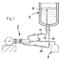
- Fig. 1 Such a known arrangement is in Fig. 1 in which the reservoir 1 can be seen, in which the cryogenic fluid F to be pumped is provided, which has a liquid phase and a gas above it. having vapor phase.
- the reservoir 1 is preferably arranged above the pump 2 and connected via a supply line 10, in which preferably a valve 11 is present, with the input of the pump 2.
- the primary output of the pump 2 is connected via a line 12 here with a filling device 3, while the secondary output of the pump 2 is connected via a return line 13 to the reservoir 1, wherein in the return line 13 preferably also a valve 14 is present ,
- the filling device 3 can be designed, for example, for filling gas cylinders, such as are used during welding.
- the cryogenic fluid passes from the reservoir 1 to the input of the pump 2. That part of the fluid that enters the pumping chamber is compressed and passes through the primary outlet of the pump 2 and through the line 12 to the filling device. That part of the fluid which flows around the bushing to the secondary outlet of the pump 2 absorbs heat arising during the compression of the fluid (thus cools the bushing) and is returned to the reservoir 1 through the return line 13.
- the sleeve is at one end to a self-provided in the housing stop, while the other end of the socket is in engagement with a screwed into the housing end piece.
- the bushing In order for the bushing to be centered in the housing, it is provided with ribs on its outer wall over a substantial part of the length of the bush, which extend in the direction of the longitudinal axis of the housing and bear against the inner wall of the housing, thus providing centering the socket is effected. Between the ribs each valleys are provided, through which the fluid to Secondary output can flow and thereby absorb heat that arises during the compression of the fluid in the pumping chamber.
- the centering of the socket in the housing can be reliably done by the interaction of the ribs with the inner wall of the housing, the inner wall of the housing must have a high quality at least in this area, typically the inner wall of the housing is honed at least in this area. Also, the outer surfaces of the ribs of the sleeve, which are supported on the inner wall of the housing, must have a high quality and are also typically honed.
- the insert piece has a receptacle in which the stop surface is provided for the one end of the bush (and not in the housing itself).
- the sleeve is formed so that over the entire length of the sleeve between the outer wall of the sleeve and the inner wall of the housing, an annular space is formed around the sleeve around, so that the socket only by receiving the insert and by pressing the sleeve against the stop surface is centered in the housing from the other end of the sleeve.
- the socket is now based nowhere against the inner wall of the housing - so that the centering of Socket not over a longer contact surface between the socket (or their ribs) and the inner wall of the housing takes place, but only through the receptacle in which one end of the socket is received, and by pressing the socket in the receptacle and against the stop surface of other end of the jack.
- the costly and costly honing of the inner wall of the housing and the outer surface of the socket can be completely eliminated, which makes the production of the pump technically much easier and beyond also much cheaper. In addition, this measure also practically does not affect the "naturally" forming flow of the fluid towards the secondary outlet.
- a separate end piece disposed in the housing is provided which engages with the other end of the socket to press the socket against the abutment surface in the receptacle of the insert.
- the housing, the insert piece, the bushing and the end piece are designed such that when the pump is assembled the insert piece, the bushing and the end piece can be introduced into the interior of the housing from the same side.
- an arrangement of seals for sealingly performing the piston rod is provided in the interior of the insert, wherein the insert together with the arrangement of seals forms a pre-assembled module, which is used as a module in the housing during assembly of the pump. This also facilitates the assembly of the pump and / or the disassembly of the pump for maintenance and repair purposes.
- the inventive pump has the housing in the region in which the tail is inserted into the housing, on its inner wall extending in the axial direction of the housing and short relative to the length of the tail seat.
- the end piece has a radially outwardly extending flange whose outer surface bears against the seat surface of the inner wall of the housing, so that the flange is guided.
- the seat surface is of high quality (e.g., honed), as is the outer surface of the flange, but only very short in the axial direction, so that the expense of producing a surface of this quality remains relatively low.
- the tolerances to be maintained which are required in the production of the most accurate guidance, can be controlled well on a surface with a short length, while this becomes more difficult and expensive with increasing length of the surface.
- an internal thread is further provided on the inner wall of the housing, in which a support ring is screwed, which in turn has an internal thread into which engages a push-on the end piece pressure screw.
- the pressure screw is actuated from outside the housing and is operated during assembly of the pump to press the tail firmly against the socket and thus to fix the socket centered in the housing.
- a cylindrical receptacle for a connecting piece is provided at the input and / or at the secondary output, which can be taken in a plane perpendicular to the longitudinal axis of the cylindrical receptacle rotated by an arbitrary angle of the recording.
- means for fixing the nozzle in the receptacle are provided at the entrance and / or at the secondary outlet.
- a jacket enclosing the housing is fastened to the outside of the housing.
- This jacket together with the outer wall of the housing, defines a cavity which is evacuated or connected to a connection enabling the evacuation of this cavity.
- the cavity extends at least over most of the socket away. The evacuation of the cavity and the additional outer jacket thus allow quasi a decoupling of the temperature in the housing at least in the region of the socket) of the ambient temperature.
- Fig. 2 a longitudinal section through a Embodiment of a pump 2 according to the invention.
- the pump 2 has a housing 20 which has an inlet 21 for the fluid to be pumped.
- a cylindrical receptacle 210 is screwed into the housing 20, which has a connecting piece 100 of the supply line 10 (FIG. Fig.1 ) and which is sealed by means of a seal 211 to the outside.
- the nozzle 100 is rotatable in a plane perpendicular to the longitudinal axis 212 of the cylindrical receptacle 210 by any angle (virtually in the "azimuth plane") and can be recorded at any such angle in the receptacle 210.
- a union nut 212 By means of a union nut 212, the nozzle 100 can then be fixed in the receptacle 210.
- a port 130 of the return line 13 (FIG. Fig. 1 ) in a receptacle 220, which is sealed by means of a seal 221.
- the nozzle 130 can be fixed by means of a union nut 222, which takes place in the same manner as previously described at the input 20 of the pump 2, which is why at this point a further explanation is unnecessary.
- Fig. 2 still the primary output 23 of the pump 2, through which the compressed fluid in the line 12 ( Fig. 1 ) entering, for example, the filling device 3 (FIG. Fig. 1 ) leads.
- an insert 24 is arranged, which has a receptacle 240 with a stop surface 240a.
- the receptacle 240 receives the one end of a socket 25 and carries this end of the socket 25, which will be discussed in more detail below.
- a Arrangement of seals 241 provided for sealingly performing a piston rod 260 which is connected to a piston 26 which is provided with piston rings 261.
- the piston 26 is slidably disposed in the sleeve 25.
- a check valve 262 is arranged, which comprises a valve stem 262a and a return spring 262b.
- seals 241 in the insert 24 forms in the embodiment shown, together with the insert 24, a pre-assembled module, which can be mounted outside the housing 20 ready, so then the entire module can be inserted into the housing 20, and here of the right side of the housing 20 ago, an introduction of the insert 24 into the housing 20 from the left side is not possible here.
- the piston rod 260 (with the attached piston 26) can be outside the housing 20 already in the module (insert 24 together with seal assembly 241) are introduced and then introduced into the housing 20 together with the module. But it is also possible to first introduce the module (insert 24 together with seal assembly 241) in the housing 20 and then to introduce the piston rod 260 in the already inserted in the housing 20 module. Thus, e.g. the piston 26 are inserted outside the housing 20 in the socket 25, and the piston rod 260 can then be introduced into the housing 20 together with the piston 26 and the sleeve 25.
- one end of the bushing 25 is received in the receptacle 240 of the insert piece 24.
- the inputs for the fluid in the interior of the sleeve 25 wherein at these inputs filter elements 250 are provided which may contain particles contained in the fluid, thus the piston 26 can not seize.
- the other end of the bushing 25 is fixed in the housing 20 by means of an end piece 27, which engages with this end bushing 25.
- the end piece 27 is also introduced from the right side into the housing 20 until it engages in the end of the socket 25 facing it.
- a seal 267 is provided, which may be formed, for example, as a copper seal, since it still has to seal even at the high pressures occurring there.
- the end piece 27 has a radially outwardly extending flange 270, which abuts against a corresponding seat surface 200 which is provided on the inner wall of the housing 20.
- This seat surface 200 and the corresponding outer surface of the flange extend in the axial direction of the housing relative to the length of the end piece 27 only over a relatively short distance.
- the seat surface 200 forms a guide for the voltage applied to the inner wall of the housing 20 outer surface of the flange 270, whereby the flange 270 and thus the tail 27 is guided.
- Both the seat 200 and the voltage applied to her outer surface of the flange 270 must therefore be made with high accuracy, however, this requirement of high accuracy is limited to a relatively short piece, which is well manageable manufacturing technology, since the compliance with tight tolerances over a short Piece is better possible than adhering closely Tolerances over a longer piece. It is also cheaper.
- the bushing 25 is held centered between the end piece 27 and the receptacle 240 of the insert piece 24, including the seat surface 200 and the outer surface of the flange 270 educated leadership contributes.
- the end piece 27 still has to be fixed, that is to say fixedly arranged in the housing 20, so that the socket 25 is likewise firmly held in the housing 20.
- the housing 20 is provided at this end with an internal thread 201 into which a support ring 28 is screwed.
- the support ring 28 in turn has an internal thread 280 into which the external thread of a pressure screw 29 engages, which can be actuated even after screwing into the internal thread of the support ring 28 from outside the housing and which transmits the forces on the end piece 27 to the tail 27 and thus the socket 25 finally fix in the housing 20.
- a pressure plate 29 a is arranged, whereby the pinch seal 271 is clamped and the forces are transmitted from the pressure screw 29 to the end piece 27.
- Screwing the pressure screw in the support ring 28 thus facilitates the assembly and disassembly of the pump, possibly even simpler tools can be used for tightening, because just only lower torques for applying the same force are required.
- a check valve is arranged, which comprises a two-part valve body 272, namely a first, movable part 272a and a second, screwed into an internal thread of the end piece 27 fixed part 272b includes, and arranged between these two parts 272a and 272b Spring 272c.
- the movable part 272a is provided with two through holes 272d. In the illustrated position of the movable part 272a of the valve body 272, this movable part 272a closes the primary outlet 23 of the pump.
- the primary outlet 23 is sealed by a clamped by the fixed part 272 b of the valve body 272 272 e seal.
- a shell 202 enclosing the housing (here, for example, by welding) which, together with the outer wall of the housing 20, defines a cavity 202a which can be evacuated via the connection port 202b.
- the cavity 202a extends practically over the entire length of the bushing 25 and serves to decouple the housing 20 in the region of the socket 25 from the ambient temperature, wherein the evacuated cavity 202a is an extremely poor heat conductor and thus virtually causes the temperature decoupling.
- a heating sleeve 203 is arranged around the housing 20, which can heat the housing 20 in this part, so that it can not freeze at this end, because at this end the housing 20 eg connected via a thread 204 with a (not shown) drive device and countered with the lock nut 205, so that the drive device with the end of the piston rod 260, which faces away from the piston 26 is engaged and the piston rod 260 and thus the piston 26 in the Socket 25 eg motor can move back and forth.
- the fluid then passes from the pumping chamber through the primary outlet 23 and further through the openings 272d in the movable part 272b into the interior of the check valve 272 and from there into the conduit 10 (FIG. Fig. 1 ) leading to the filling device 3 ( Fig. 1 ) leads.
- the arrangement of the spring 272c is advantageous in that it does not come to lie partially over the openings 272d and thus always has contact with the fixed part 272a and the movable part 272b of the check valve 272, whereby upon closure of the valve - at the end the compression stroke - the spring can not strike against the movable part 272b of the check valve (because it has been previously lifted by the pressure of the fluid flowing through it, for example) and thus the life of this spring is increased.
- the fluid flows not only through the interior of the piston 26 in the pumping chamber and from there through the primary outlet 23 into the conduit 10 into it, but a part of the fluid also flows through the annular space between the housing 20 and the socket 25th is formed.
- This fluid which flows around the bushing 15, absorbs heat that may arise during the compression stroke.
- the fluid then flows through the secondary outlet 22 and through the return line 13 (FIG. Fig. 1 ) back into the reservoir 1 through.
Landscapes
- Engineering & Computer Science (AREA)
- Mechanical Engineering (AREA)
- General Engineering & Computer Science (AREA)
- Details Of Reciprocating Pumps (AREA)
- Structures Of Non-Positive Displacement Pumps (AREA)
Description
- Die Erfindung betrifft eine Pumpe für ein kryogenes Fluid gemäss dem Oberbegriff des unabhängigen Patentanspruchs.
- Solche Pumpen kommen beispielsweise zum Pumpen eines Fluids zum Einsatz, welches mindestens teilweise aus einem verflüssigten Gas - wie z.B. Stickstoff, Sauerstoff oder Argon - besteht und eventuell auch noch gasförmiges Fluid aufweist. Die Pumpe kann beispielsweise zum Einsatz kommen, um Fluid aus einem Reservoir in einen Behälter oder irgendeine Vorrichtung zu pumpen und den Druck dabei wesentlich zu erhöhen, z.B. kann sie beim Befüllen von Gasflaschen, wie sie beim Schweissen zum Einsatz kommen, Anwendung finden.
- Eine derartige Pumpe für ein solches kryogenes Fluid ist beispielsweise aus der
EP-A-0 730 092 bekannt. Die dort beschriebene Pumpe weist ein Gehäuse mit einem Eingang für das zu pumpende Fluid auf, sowie einen Primär-Ausgang und einen Sekundär-Ausgang. Im Gehäuse ist eine Buchse angeordnet, die mit ihrem einen Ende an einem im Gehäuse selbst vorgesehenen Anschlag anliegt. Mit einem in das Gehäuse einschraubbaren Endstück steht das andere Ende der Buchse in Eingriff. Damit die Buchse zentriert im Gehäuse angeordnet ist, ist sie auf ihrer Aussenwand über einen wesentlichen Teil der Länge der Buchse mit Rippen versehen, die sich in Richtung der Längsachse des Gehäuses erstrecken und sich an der Innenwand des Gehäuses abstützen, sodass auf diese Weise die Zentrierung der Buchse bewirkt wird. Zwischen den Rippen sind jeweils Täler vorgesehen, auf deren Funktion weiter unten noch eingegangen wird. - In der Buchse ist ein Kolben verschiebbar angeordnet, der mit einer Kolbenstange verbunden ist. Im Gehäuse ist ferner ein Einsatzstück angeordnet, welches in das Gehäuse vom anderen Ende her einbringbar ist als die Buchse und das Endstück. Die Kolbenstange ist durch dieses Einsatzstück durchgeführt und von ausserhalb des Gehäuses antreibbar.
- Der Kolben begrenzt eine Pumpkammer, die über ein Rückschlagventil mit dem Eingang für das Fluid verbunden ist. Dieses Rückschlagventil ist so ausgebildet, dass beim Ansaughub des Kolbens das Rückschlagventil geöffnet ist und das zu pumpende Fluid in die Pumpkammer strömt, während beim Kompressionshub des Kolbens das Rückschlagventil geschlossen ist, sodass das in der Pumpkammer befindliche Fluid entsprechend mit Druck beaufschlagt wird.
- Der Eingang für das Fluid ist ferner über einen zwischen der Buchse und der Innenwand des Gehäuses gebildeten Zwischenraum mit dem Sekundär-Ausgang verbunden. Wie weiter oben bereits erwähnt, sind zwischen den Rippen, die sich gegen die Innenwand des Gehäuses abstützen, Täler vorgesehen. Durch diese Täler kann in demjenigen Bereich der Buchse, in welchem die Rippen vorgesehen sind, das Fluid zum Sekundärausgang strömen. Das Fluid umströmt somit die Buchse, was insofern vorteilhaft ist, als es Wärme aufnehmen kann, welche bei der Kompression des Fluids in der Pumpkammer (also auf dem "Primärweg" des Fluids) entsteht. Das aus dem Sekundär-Ausgang austretende erwärmte Fluid kann dann zu dem Reservoir zurückgeführt werden aus dem es ursprünglich der Pumpe zugeführt wurde.
- Eine derartige bekannte Anordnung ist in
Fig. 1 gezeigt, in welcher das Reservoir 1 zu erkennen ist, in welchem das zu pumpende kryogene Fluid F bereitgestellt wird, welches eine flüssige Phase und eine sich darüber befindliche gas- bzw. dampfförmige Phase aufweist. Das Reservoir 1 ist vorzugsweise oberhalb der Pumpe 2 angeordnet und über eine Zuleitung 10, in welcher vorzugsweise ein Ventil 11 vorhanden ist, mit dem Eingang der Pumpe 2 verbunden. Der Primär-Ausgang der Pumpe 2 ist über eine Leitung 12 hier mit einer Abfüllvorrichtung 3 verbunden, während der Sekundär-Ausgang der Pumpe 2 über eine Rückleitung 13 mit dem Reservoir 1 verbunden ist, wobei in der Rückleitung 13 vorzugsweise ebenfalls ein Ventil 14 vorhanden ist. Die Abfüllvorrichtung 3 kann beispielsweise für die Befüllung von Gasflaschen, wie sie beim Schweissen zum Einsatz kommen, ausgebildet sein. - Durch die Zuleitung 10 gelangt das kryogene Fluid aus dem Reservoir 1 zum Eingang der Pumpe 2. Derjenige Teil des Fluids, der in die Pumpkammer gelangt, wird komprimiert und gelangt durch den Primär-Ausgang der Pumpe 2 und durch die Leitung 12 zur Abfüllvorrichtung. Derjenige Teil des Fluids, der um die Buchse herum zum Sekundär-Ausgang der Pumpe 2 strömt, nimmt bei der Kompression des Fluids entstehende Wärme auf (kühlt also die Buchse) und wird durch die Rückleitung 13 zum Reservoir 1 zurückgeführt.
- Wie bereits weiter oben beschrieben, liegt die Buchse mit ihrem einen Ende an einem im Gehäuse selbst vorgesehenen Anschlag an, während das andere Ende der Buchse mit einem in das Gehäuse einschraubbaren Endstück in Eingriff steht. Damit die Buchse zentriert im Gehäuse angeordnet ist, ist sie auf ihrer Aussenwand über einen wesentlichen Teil der Länge der Buchse mit Rippen versehen, die sich in Richtung der Längsachse des Gehäuses erstrecken und sich an der Innenwand des Gehäuses abstützen, sodass auf diese Weise die Zentrierung der Buchse bewirkt wird. Zwischen den Rippen sind jeweils Täler vorgesehen, durch die das Fluid zum Sekundär-Ausgang strömen kann und dabei Wärme aufnehmen kann, die bei der Kompression des Fluids in der Pumpkammer entsteht.
- Damit die Zentrierung der Buchse im Gehäuse zuverlässig durch das Zusammenwirken der Rippen mit der Innenwand des Gehäuses erfolgen kann, muss die Innenwand des Gehäuses wenigstens in diesem Bereich eine hohe Güte aufweisen, typischerweise ist die Innenwand des Gehäuses zumindest in diesem Bereich gehont. Auch die Aussenflächen der Rippen der Buchse, die sich an der Innenwand des Gehäuses abstützen, müssen eine hohe Güte aufweisen und sind typischerweise ebenfalls gehont.
- Das Honen der Innenwand des Gehäuses über eine doch recht erhebliche Länge hinweg sowie das Honen der Aussenflächen der Rippen sind aufwendige und auch kostspielige Vorgänge, die die Pumpe technisch aufwendig und teuer machen. Darüber hinaus wird auch die sich "natürlich" ausbildende Strömung des Fluids in Richtung zum Sekundär-Ausgang hin durch die Rippen nachteilig beeinflusst, weil sie eben gezwungen wird, durch zwischen den Rippen gebildeten Täler zu strömen, sodass es vermehrt zu Wirbeln in der Strömung kommen kann.
- Hier setzt die vorliegende Erfindung an, deren Aufgabe es ist, eine Pumpe für ein kryogenes Fluid vorzuschlagen, welche herstellungstechnisch weniger aufwendig und dadurch auch kostengünstiger ist und welche nach Möglichkeit die sich "natürlich" ausbildende Strömung zum Sekundär-Ausgang der Pumpe hin möglichst nicht beeinflusst.
- Diese Aufgabe wird durch die erfindungsgemässe Pumpe, wie sie durch die Merkmale des unabhängigen Patentanspruchs definiert ist, gelöst. Vorteilhafte Weiterbildungen ergeben sich aus den Merkmalen der abhängigen Patentansprüche.
- Insbesondere ist es bei der erfindungsgemässen Pumpe so, dass das Einsatzstück eine Aufnahme aufweist, in welcher die Anschlagfläche für das eine Ende der Buchse vorgesehen ist (und nicht im Gehäuse selbst). Die Buchse ist so ausgebildet, dass über die gesamte Länge der Buchse hinweg zwischen der Aussenwand der Buchse und der Innenwand des Gehäuses ein ringförmiger Zwischenraum um die Buchse herum gebildet wird, sodass die Buchse lediglich durch die Aufnahme des Einsatzstücks und durch das Andrücken der Buchse gegen die Anschlagfläche vom anderen Ende der Buchse her zentriert im Gehäuse gehalten wird.
- Zwischen der Buchse und der Innenwand des Gehäuses besteht also über die gesamte Länge der Buchse hinweg ein ringförmiger Zwischenraum (durch den dann das Fluid zum Sekundär-Ausgang strömt) - die Buchse stützt sich also nirgendwo gegen die Innenwand des Gehäuses ab - sodass die Zentrierung der Buchse nicht über eine längere Kontaktfläche zwischen Buchse (bzw. deren Rippen) und Innenwand des Gehäuses erfolgt, sondern lediglich durch die Aufnahme, in welcher das eine Ende der Buchse aufgenommen wird, und durch das Drücken der Buchse in die Aufnahme und gegen deren Anschlagfläche vom anderen Ende der Buchse her. Das aufwendige und kostspielige Honen der Innenwand des Gehäuses und der Aussenfläche der Buchse kann dadurch völlig entfallen, was die Herstellung der Pumpe technisch wesentlich vereinfacht und darüber hinaus auch wesentlich kostengünstiger ist. Ausserdem wird durch diese Massnahme auch die sich "natürlich" ausbildende Strömung des Fluids zum Sekundär-Ausgang hin praktisch nicht beeinflusst.
- Bei der Pumpe ist ein in dem Gehäuse angeordnetes separates Endstück vorgesehen, welches mit dem anderen Ende der Buchse in Eingriff steht, um die Buchse gegen die Anschlagfläche in der Aufnahme des Einsatzstücks zu drücken.
- Bei dieser Pumpe ist die Montage ebenfalls einfach, im Falle von Schäden - z.B. bei einem "Kolbenfresser" - ist jedoch die Demontage sehr viel einfacher, weil eben das Endstück ein separates Teil ist und somit im Falle des Kolbenfressers nur die Buchse ausgetauscht werden muss. Sind hingegen Buchse und Endstück nicht separat und bilden eine Einheit, muss im Falle eines "Kolbenfressers" diese gesamte Einheit ausgetauscht werden.
- Bei der erfindungsgemässen Pumpe sind das Gehäuse, das Einsatzstück, die Buchse und das Endstück so ausgebildet, dass beim Zusammenbau der Pumpe das Einsatzstück, die Buchse und das Endstück von der gleichen Seite her in den Innenraum des Gehäuses einbringbar sind.
- Dies erleichtert den Zusammenbau der Pumpe ganz erheblich, da die einzelnen Komponenten nicht von mehreren Seiten her in das Gehäuse eingebracht werden müssen und damit das Gehäuse beim Zusammenbau (oder auch bei der Demontage zu Wartungs- oder Reparaturzwecken) der Pumpe nicht ein oder mehrere Male gedreht werden muss. Die Komponenten können bei diesem Ausführungsbeispiel alle von einer Seite her in das Gehäuse der Pumpe eingebracht werden.
- Bei einem weiteren vorteilhaften Ausführungsbeispiel der erfindungsgemässen Pumpe ist im Innenraum des Einsatzstücks eine Anordnung von Dichtungen zum dichten Durchführen der Kolbenstange vorgesehen, wobei das Einsatzstück zusammen mit der Anordnung von Dichtungen ein vormontierbares Modul bildet, welches beim Zusammenbau der Pumpe als Modul in das Gehäuse eingesetzt wird. Dies erleichtert ebenfalls den Zusammenbau der Pumpe und bzw. die Demontage der Pumpe zu Wartungs- und Reparaturzwecken.
- Bei einem weiteren vorteilhaften Ausführungsbeispiel der erfindungsgemässen Pumpe hat das Gehäuse in dem Bereich, in dem das Endstück in das Gehäuse eingesetzt ist, auf seiner Innenwand eine sich in axialer Richtung des Gehäuses erstreckende und relativ zur Länge des Endstücks kurze Sitzfläche. Das Endstück weist einen sich in radialer Richtung nach aussen erstreckenden Flansch auf, dessen Aussenfläche an der Sitzfläche der Innenwand des Gehäuses anliegt, sodass der Flansch geführt ist. Die Sitzfläche ist von hoher Güte (z.B. gehont), ebenso die Aussenfläche des Flansches, jedoch in axialer Richtung betrachtet nur sehr kurz, sodass der Aufwand bei der Herstellung einer Fläche mit dieser Güte relativ gering bleibt. Ausserdem lassen sich auf einer Fläche mit kurzer Länge auch die einzuhaltenden Toleranzen, die bei der Herstellung einer möglichst exakten Führung erforderlich sind, gut beherrschen, während dies mit zunehmender Länge der Fläche schwieriger und aufwendiger wird.
- Bei diesem Ausführungsbeispiel der erfindungsgemässen Pumpe ist ferner auf der Innenwand des Gehäuses ein Innengewinde vorgesehen, in welches ein Stützring eingeschraubt ist, der seinerseits ein Innengewinde aufweist, in welches eine auf das Endstück aufschiebbare Druckschraube eingreift. Die Druckschraube ist von ausserhalb des Gehäuses betätigbar und wird beim Zusammenbau der Pumpe betätigt, um das Endstück fest gegen die Buchse zu drücken und damit die Buchse im Gehäuse zentriert zu fixieren. Dadurch, dass der Stützring in das Gehäuse eingeschraubt ist und die Druckschraube, welche letztlich die Kräfte auf das Endstück überträgt, um die Buchse zentriert im Gehäuse zu fixieren, in das Innengewinde des Stützrings eingreift (und sich dort abstützt), muss zur Erzeugung der für die Fixierung der Buchse erforderlichen Kräfte von ausserhalb des Gehäuses nur ein geringeres Drehmoment aufgewendet werden als wenn die Druckschraube direkt in das Innengewinde des Gehäuses eingreifen würde. Dies erleichtert den Zusammenbau bzw. die Demontage der Pumpe, weil wesentlich geringere Drehmomente aufgebracht werden müssen zur Erzeugung der Kräfte auf das Endstück, welches die Buchse zentriert im Gehäuse fixiert. Dies kann sogar bedeuten, dass einfachere Werkzeuge, mit denen das erforderliche Drehmoment aufgebracht wird, verwendet werden können.
- Bei einem weiteren vorteilhaften Ausführungsbeispiel der erfindungsgemässen Pumpe ist am Eingang und/oder am Sekundär-Ausgang eine zylindrische Aufnahme für einen Stutzen vorgesehen, der in einer Ebene senkrecht zur Längsachse der zylindrischen Aufnahme um einen beliebigen Winkel verdreht von der Aufnahme aufgenommen werden kann. Ausserdem sind am Eingang und/oder am Sekundär-Ausgang Mittel zum Fixieren des Stutzens in der Aufnahme vorgesehen. Dies erleichtert den Aufbau der Pumpe insofern, als die Zuführ- und Rückführleitung im wesentlichen so angeordnet werden kann, wie es von den räumlichen Gegebenheiten am Ort, an dem die Pumpe aufgestellt werden soll, am besten möglich ist. Der Stutzen kann jedenfalls in jede beliebige "azimutale" Richtung (bezogen auf die Längsachse der Aufnahme) gedreht und dann in dieser Richtung fixiert werden. Vor allem dann, wenn die Rohrleitungen an dem Ort, an welchem die Pumpe aufgestellt werden soll, schon fest installiert sind, erhöht dies die Flexibilität der Pumpe.
- Bei einem weiteren vorteilhaften Ausführungsbeispiel der erfindungsgemässen Pumpe ist aussen an dem Gehäuse ein das Gehäuse umschliessender Mantel befestigt. Dieser Mantel begrenzt zusammen mit der Aussenwand des Gehäuses einen Hohlraum, welcher evakuiert ist oder mit einem die Evakuation dieses Hohlraums ermöglichenden Anschluss verbunden ist. Der Hohlraum erstreckt sich dabei zumindest über den grössten Teil der Buchse hinweg. Die Evakuation des Hohlraums und der zusätzlich Aussenmantel erlauben somit quasi eine Entkopplung der Temperatur im Gehäuse zumindest im Bereich der Buchse) von der Umgebungstemperatur.
- Weitere vorteilhafte Ausgestaltungen der erfindungsgemässen Pumpe ergeben sich aus der nachfolgenden Erläuterung eines vorteilhaften Ausführungsbeispiels der erfindungsgemässen Pumpe mit Hilfe der Zeichnung.
-
- Fig. 1
- eine Ansicht einer Pumpe gemäss dem Stand der Technik mit der Pumpe verbundenes Reservoir sowie eine mit dem Primär-Ausgang der Pumpe verbundene Abfüllvorrichtung,
und - Fig. 2
- einen Längsschnitt durch ein Ausführungsbeispiel einer erfindungsgemässen Pumpe.
- Während die grundsätzliche Anwendung einer solchen Pumpe bereits weiter oben anhand der
Fig. 1 erläutert worden ist, erkennt man inFig. 2 einen Längsschnitt durch ein Ausführungsbeispiel einer erfindungsgemässen Pumpe 2. - Die Pumpe 2 weist ein Gehäuse 20 auf, welches einen Eingang 21 für das zu pumpende Fluid aufweist. Am Eingang 21 ist eine zylindrische Aufnahme 210 in das Gehäuse 20 eingeschraubt, die einen Stutzen 100 der Zuleitung 10 (
Fig.1 ) aufnimmt und die mittels einer Dichtung 211 nach aussen hin abgedichtet ist. Der Stutzen 100 ist in einer Ebene senkrecht zur Längsachse 212 der zylindrischen Aufnahme 210 um einen beliebigen Winkel verdrehbar (quasi in der "Azimutebene") und kann unter jedem beliebigen solchen Winkel in der Aufnahme 210 aufgenommen werden. Mittels einer Überwurfmutter 212 kann dann der Stutzen 100 in der Aufnahme 210 fixiert werden. - Am Sekundär-Ausgang 22 ist in gleicher Weise wie am Eingang ein Stutzen 130 der Rückleitung 13 (
Fig. 1 ) in einer Aufnahme 220 anbringbar, die mittels einer Dichtung 221 abgedichtet ist. Der Stutzen 130 kann mittels einer Überwurfmutter 222 fixiert werden, was in gleicher Weise erfolgt wie zuvor am Eingang 20 der Pumpe 2 beschrieben, weshalb sich an dieser Stelle eine weitergehende Erläuterung erübrigt. - Ferner erkennt man in
Fig. 2 noch den Primär-Ausgang 23 der Pumpe 2, durch welchen das komprimierte Fluid in die Leitung 12 (Fig. 1 ) eintritt, die beispielsweise zu der Abfüllvorrichtung 3 (Fig. 1 ) führt. - Im Gehäuse 20 ist ein Einsatzstück 24 angeordnet, welches eine Aufnahme 240 mit einer Anschlagfläche 240a aufweist. Die Aufnahme 240 nimmt das eine Ende einer Buchse 25 auf und führt dieses Ende der Buchse 25, worauf weiter unten noch genauer eingegangen wird. In dem Einsatzstück 24 ist eine Anordnung von Dichtungen 241 zum dichten Durchführen einer Kolbenstange 260 vorgesehen, die mit einem Kolben 26 verbunden ist, der mit Kolbenringen 261 versehen ist. Der Kolben 26 ist in der Buchse 25 verschiebbar angeordnet. Im Kolben 26 ist ein Rückschlagventil 262 angeordnet, welches einen Ventilstössel 262a und eine Rückstellfeder 262b umfasst. Die Anordnung von Dichtungen 241 im Einsatzstück 24 bildet bei dem gezeigten Ausführungsbeispiel zusammen mit dem Einsatzstück 24 ein vormontierbares Modul, welches ausserhalb des Gehäuses 20 fertig montiert werden kann, sodass dann das gesamte Modul in das Gehäuse 20 eingebracht werden kann, und zwar hier von der rechten Seite des Gehäuses 20 her, ein Einbringen des Einsatzstücks 24 in das Gehäuse 20 von der linken Seite her ist hier nicht möglich.
- Auch die Kolbenstange 260 (mit dem daran befestigten Kolben 26) kann ausserhalb des Gehäuses 20 bereits in das Modul (Einsatzstück 24 mitsamt Dichtungsanordnung 241) eingebracht werden und zusammen mit dem Modul dann in das Gehäuse 20 eingebracht werden. Es ist aber auch möglich, zuerst das Modul (Einsatzstück 24 mitsamt Dichtungsanordnung 241) in das Gehäuse 20 einzubringen und anschliessend die Kolbenstange 260 in das bereits im Gehäuse 20 eingesetzte Modul einzubringen. So kann z.B. der Kolben 26 ausserhalb des Gehäuses 20 in die Buchse 25 eingesetzt werden, und die Kolbenstange 260 kann dann mitsamt dem Kolben 26 und der Buchse 25 in das Gehäuse 20 eingebracht werden.
- Wie bereits erwähnt, wird das eine Ende der Buchse 25 in der Aufnahme 240 des Einsatzstücks 24 geführt aufgenommen. Im Bereich dieses Endes befinden sich auch die Eingänge für das Fluid in den Innenraum der Buchse 25, wobei an diesen Eingängen Filterelemente 250 vorgesehen sind, welche eventuell im Fluid enthalten Partikel zurückhalten, damit der Kolben 26 sich nicht festfressen kann. Das andere Ende der Buchse 25 wird mit Hilfe eines Endstücks 27, welches mit diesem Ende Buchse 25 in Eingriff steht, im Gehäuse 20 fixiert. Dazu wird das Endstück 27 ebenfalls von der rechten Seite her in das Gehäuse 20 eingebracht, bis es in das ihm zugewandte Ende der Buchse 25 eingreift. Zu diesem Zweck ist am diesem dem Endstück 27 zugewandten Ende der Buchse 25 eine Aufnahme an der Buchse 25 ausgebildet, in die das der Buchse 25 zugewandte Ende des Endstück 27 eingreift, bis die Stirnfläche dieses Endes des Endstücks 27 an einer Anschlagfläche der Aufnahme der Buchse 25 anliegt. Zwischen der Stirnfläche des Endes des Endstücks 27 und der Anschlagfläche der an der Buchse 25 vorgesehenen Aufnahme ist eine Dichtung 267 vorgesehen, die beispielsweise als Kupferdichtung ausgebildet sein kann, da sie auch bei den dort auftretenden hohen Drücken noch abdichten muss.
- Das Endstück 27 weist einen sich in radialer Richtung nach aussen hin erstreckenden Flansch 270 auf, der an einer entsprechenden Sitzfläche 200, die an der Innenwand des Gehäuses 20 vorgesehen ist, anliegt. Diese Sitzfläche 200 und die entsprechende Aussenfläche des Flansches erstrecken sich in axialer Richtung des Gehäuses relativ zu der Länge des Endstücks 27 nur über ein relativ kurzes Stück. Die Sitzfläche 200 bildet eine Führung für die an der Innenwand der Gehäuses 20 anliegende Aussenfläche des Flansches 270, wodurch der Flansch 270 und damit das Endstück 27 geführt ist. Sowohl die Sitzfläche 200 als auch die an ihr anliegende Aussenfläche des Flansches 270 müssen daher mit hoher Genauigkeit hergestellt sein, allerdings beschränkt sich dieses Erfordernis der hohen Genauigkeit auf ein relativ kurzes Stück, was herstellungstechnisch gut beherrschbar ist, da die Einhaltung enger Toleranzen über ein kurzes Stück besser möglich ist als die Einhaltung enger Toleranzen über ein längeres Stück. Ausserdem ist es auch kostengünstiger.
- Greift das der Buchse 25 zugewandte Ende des Endstücks 27 in die Aufnahme der Buchse 25 ein, so wird die Buchse 25 zentriert zwischen dem Endstück 27 und der Aufnahme 240 des Einsatzstücks 24 gehalten, wozu auch die von der Sitzfläche 200 und der Aussenfläche des Flansches 270 gebildete Führung beiträgt. Allerdings muss das Endstück 27 noch fixiert werden, also im Gehäuse 20 fest angeordnet werden, damit die Buchse 25 ebenfalls im Gehäuse 20 fest gehalten ist.
- Zu diesem Zweck ist das Gehäuse 20 an diesem Ende mit einem Innengewinde 201 versehen, in welches ein Stützring 28 eingeschraubt ist. Der Stützring 28 weist seinerseits ein Innengewinde 280 auf, in welches das Aussengewinde einer Druckschraube 29 eingreift, welche auch nach dem Einschrauben in das Innengewinde des Stützrings 28 von ausserhalb des Gehäuses betätigt werden kann und welche die Kräfte auf das Endstück 27 überträgt, um das Endstück 27 und damit die Buchse 25 schliesslich im Gehäuse 20 zu fixieren. Zwischen der Druckschraube 29 und dem Endstück 27 ist eine Druckscheibe 29a angeordnet, wodurch die Quetschdichtung 271 eingeklemmt wird und die Kräfte von der Druckschraube 29 auf das Endstück 27 übertragen werden.
- Dadurch, dass sich die Druckschraube 29 beim Einschrauben am Innengewinde 280 des Stützrings 28 abstützt (der sich seinerseits am Innengewinde 201 des Gehäuses 20 abstützt), wird nur ein geringeres Drehmoment erforderlich zur Übertragung einer bestimmten Kraft auf das Endstück 27 (über die Druckscheibe 29a) als bei der Übertragung einer gleich grossen Kraft und einer Abstützung des Aussengewindes der Druckschraube 29 direkt am Innengewinde 201 des Gehäuses.
- Das Einschrauben der Druckschraube in den Stützring 28 erleichtert somit den Zusammenbau bzw. die Demontage der Pumpe, ggf. können sogar einfachere Werkzeuge zum Festziehen verwendet werden, weil eben nur noch geringere Drehmomente zum Aufbringen der gleichen Kraft erforderlich sind.
- Vorteilhaft ist auch, dass beim Fixieren des Endstücks 27 das Endstück 27 selbst nicht in das Gehäuse 20 eingeschraubt wird, sondern lediglich nach links in das Gehäuse 20 hinein geschoben und anschliessend mittels Druckscheibe 29a, Druckschraube 29 und Stützring 28 fixiert wird. Auf diese Weise wird vermieden, dass die der Buchse 25 zugewandte Stirnfläche des Endstücks 27 beim Fixieren auf der (Kupfer-) Dichtung 267 reibt und deren Dichtigkeit beeinträchtigen oder verringern kann. Würde das Endstück 27 in das Gehäuse 20 oder in den Stützring 28 eingeschraubt werden müssen, so könnte es beim Festziehen zu einer solchen Beeinträchtigung kommen, die durch die vorliegende Art der Ausführung von Endstück 27, Stützring 28, Druckscheibe 29a und Druckschraube 29 vermieden wird.
- In dem Endstück 27 ist ein Rückschlagventil angeordnet, welches einen zweiteiligen Ventilkörper 272 umfasst, nämlich einen ersten, bewegbaren Teil 272a und einen zweiten, in ein Innengewinde des Endstücks 27 eingeschraubten fest angeordneten Teil 272b umfasst, sowie eine zwischen diesen beiden Teilen 272a und 272b angeordnete Feder 272c. Der bewegbare Teil 272a ist mit zwei Durchgangsbohrungen 272d versehen. In der gezeigten Stellung des bewegbaren Teils 272a des Ventilkörpers 272 verschliesst dieser bewegbare Teil 272a den Primär-Ausgang 23 der Pumpe. Er ist aber gegen die Rückstellkraft der Feder 272c in Richtung auf den fest angeordneten Teil 272b des Ventilkörpers 272 in Richtung auf den feststehenden Teil 272b zu bewegbar, wodurch das komprimierte Fluid durch die Durchgangsbohrungen 272d (und durch den Innenraum des Ventilkörpers 272) hindurch in die Leitung 10 (
Fig. 1 ) und damit zu der Abfüllvorrichtung 3 gelangen kann. Auf die genaue Funktionsweise wird weiter unten noch eingegangen. Nach aussen hin ist der Primär-Ausgang 23 durch eine von dem fest angeordneten Teil 272b des Ventilkörpers 272 eingeklemmte Dichtung 272e abgedichtet. - Aussen an dem Gehäuse 20 ist ein das Gehäuse umschliessender Mantel 202 befestigt (hier z.B. durch Schweissen), welcher zusammen mit der Aussenwand des Gehäuses 20 einen Hohlraum 202a begrenzt, der über den Anschluss-Stutzen 202b evakuiert werden kann. Der Hohlraum 202a erstreckt sich praktisch über die gesamte Länge der Buchse 25 hinweg und dient dazu, das Gehäuse 20 im Bereich der Buchse 25 von der Umgebungstemperatur zu entkoppeln, wobei der evakuierte Hohlraum 202a ein extrem schlechter Wärmeleiter ist und somit quasi die temperaturmässige Entkopplung bewirkt.
- In Richtung auf das dem Kolben 26 abgewandte Ende der Kolbenstange 260 hin ist um das Gehäuse 20 herum eine Heizmanschette 203 angeordnet, welche das Gehäuse 20 in diesem Teil beheizen kann, damit es an diesem Ende nicht gefrieren kann, denn an diesem Ende wird das Gehäuse 20 z.B. über ein Gewinde 204 mit einer (nicht dargestellten) Antriebsvorrichtung verbunden und mit der Kontermutter 205 gekontert, sodass die Antriebsvorrichtung mit dem Ende der Kolbenstange 260, welches dem Kolben 26 abgewandt ist, in Eingriff steht und die Kolbenstange 260 und damit den Kolben 26 in der Buchse 25 z.B. motorisch hin- und her bewegen kann.
- Im folgenden wird die Funktion der Pumpe 2 näher beschrieben, wobei die Funktionsweise der Pumpe 2 grundsätzlich ähnlich ist wie bereits in der eingangs erwähnten EP-Ä-0 730 092 beschrieben.
- Beim Ansaughub wird die Kolbenstange 260 und damit der mit ihr verbundene Kolben 26 von dem Endstück 27 weg bewegt, in
Fig. 2 also nach links. Der Kolben 26 gleitet dabei dicht an der Innenwand der Buchse 25 entlang. Da der Ventilstössel 262b des Rückschlagventils 262 im Kolben 26 gleitend angeordnet ist, verweilt der Ventilstössel 262a beim Beginn der Bewegung des Kolbens 26 nach links zunächst in der inFig. 2 gezeigten Position, sodass bei der Bewegung des Kolbens 26 nach links durch die Öffnungen 263 im Kolben 26 Fluid durch den Einlass 21 und dann durch den Innenraum des Kolbens 26 am Ventilstössel 262a vorbei in die Pumpkammer einströmen kann, die zwischen dem Kolben 26 und dem Primär-Ausgang 23 im Endstück 27 gebildet wird. Dadurch wird die Rückstellfeder 262b komprimiert und somit gespannt. Ist der Saughub beendet, entspannt sich die Rückstellfeder 262b und drückt den Ventilstössel 262a wieder in seinen Sitz im Kolben 26, wodurch das Rückschlagventil 262 geschlossen wird. Das Rückschlagventil 272 im Endstück 27 ist während des Saughubs geschlossen, also in der Position, wie sie inFig. 2 dargestellt ist. - Beim Kompressionshub wird nun die Kolbenstange 260 und damit der mit ihr verbundene Kolben 26 auf das Endstück 27 zu bewegt, in
Fig. 2 also nach rechts. Dabei ist das Rückschlagventil 262 im Kolben 26 geschlossen. Das in der Pumpkammer befindliche - beim Saughub angesaugte - Fluid wird bei der Bewegung des Kolbens 26 nach rechts (Kompressionshub) komprimiert. Ist der Druck genügend hoch, so öffnet das Rückschlagventil 272 im Endstück 27, indem der bewegliche Teil 272a des Rückschlagventils 272 gegen die Kraft der Feder 272c auf den fest angeordneten Teil 272a des Rückschlagventils 272 zu bewegt wird. Das Fluid gelangt dann aus der Pumpkammer durch den Primär-Ausgang 23 hindurch und im weiteren durch die Öffnungen 272d im beweglichen Teil 272b in den Innenraum des Rückschlagventils 272 und von dort in die Leitung 10 (Fig. 1 ), die zur Abfüllvorrichtung 3 (Fig. 1 ) führt. Die Anordnung der Feder 272c ist hier insofern günstig, als sie auch nicht teilweise über den Öffnungen 272d zu liegen kommt und somit immer Kontakt zu dem fest angeordneten Teil 272a und dem beweglichen Teil 272b des Rückschlagventils 272 hat, wodurch beim Schliessen des Ventils - am Ende des Kompressionshubs - die Feder nicht gegen den beweglichen Teil 272b des Rückschlagventils schlagen kann (weil sie z.B. vorher durch den Druck des durchströmenden Fluids von diesem abgehoben worden ist) und somit die Lebensdauer dieser Feder erhöht wird. - Am Ende des Kompressionshubs stellt die Feder 272c den beweglichen Teil 272b des Rückschlagventils 272 wieder in die Position zurück, die in
Fig. 2 dargestellt ist, sie schliesst somit das Rückschlagventil 272. Anschliessend beginnt wieder ein neuer Saughub. - Das Fluid strömt aber nicht nur durch den Innenraum des Kolbens 26 in die Pumpkammer und aus dieser durch den Primär-Ausgang 23 in die Leitung 10 hinein, sondern ein Teil des Fluids strömt auch durch den Ringraum, der zwischen dem Gehäuse 20 und der Buchse 25 gebildet wird. Dieses die Buchse 15 umströmende Fluid nimmt Wärme auf, die beim Kompressionshub entstehen kann. Das Fluid strömt dann durch den Sekundär-Ausgang 22 hindurch und durch die Rückleitung 13 (
Fig. 1 ) hindurch wieder in das Reservoir 1 zurück.
Claims (5)
- Pumpe (2) für ein kryogenes Fluid (F), mit einem Gehäuse (20), mit einem Eingang (21) für das zu pumpende Fluid, sowie mit einem Primär-Ausgang (23) und einem Sekundär-Ausgang (22), bei welcher Pumpe im Gehäuse (20) eine Buchse (25) zentriert angeordnet ist, deren eines Ende an einer Anschlagfläche (240a) anliegt, und die von ihrem anderen Ende her gegen die Anschlagfläche (240a) gedrückt und fixiert wird, wobei in der Buchse (25) ein mit Hilfe einer Kolbenstange (260) entlang einer Achse verschiebbarer Kolben (26) angeordnet ist und die Kolbenstange (260) durch ein im Gehäuse (20) angeordnetes Einsatzstück (24) hindurchgeführt ist, und wobei der Kolben (26) eine Pumpkammer begrenzt, welche über ein erstes Rückschlagventil (262) mit dem Eingang (21) für das Fluid verbindbar ist und bei welcher am Primär-Ausgang (23) ein zweites Rückschlagventil (272) vorgesehen ist, und wobei ferner der Eingang (21) für das Fluid über einen zwischen der Buchse (25) und der Innenwand des Gehäuses (20) gebildeten Zwischenraum mit dem Sekundär-Ausgang (22) verbunden ist,
dadurch gekennzeichnet, dass das Einsatzstück (24) eine Aufnahme (240) aufweist, in welcher die Anschlagfläche (240a) für das eine Ende der Buchse (25) vorgesehen ist, und dass die Buchse (25) so ausgebildet ist, dass über die gesamte Länge der Buchse (25) hinweg zwischen der Aussenwand der Buchse (25) und der Innenwand des Gehäuses (20) ein ringförmiger Zwischenraum um die Buchse (25) herum gebildet wird, sodass die Buchse (25) lediglich durch die Aufnahme (240) des Einsatzstücks (24) und durch das Andrücken der Buchse (25) gegen die Anschlagfläche (240a) vom anderen Ende der Buchse (25) her zentriert im Gehäuse (20) gehalten wird, wobei ein in dem Gehäuse (20) angeordnetes separates Endstück (27) vorgesehen ist, welches mit dem anderen Ende der Buchse (25) in Eingriff steht, um die Buchse (25) gegen die Anschlagfläche (240a) in der Aufnahme (240) des Einsatzstücks (24) zu drücken, und wobei das Gehäuse (20), das Einsatzstück (24), die Buchse (25) und das Endstück (27) so ausgebildet sind, dass beim Zusammenbau der Pumpe das Einsatzstück (24), die Buchse (25) und das Endstück (27) von der gleichen Seite her in den Innenraum des Gehäuses (20) einbringbar sind. - Pumpe nach Anspruch 1, bei welcher im Innenraum des Einsatzstücks (24) eine Anordnung von Dichtungen (241) zum dichten Durchführen der Kolbenstange (260) vorgesehen ist, wobei das Einsatzstück (24) zusammen mit der Anordnung von Dichtungen (241) ein vormontierbares Modul bildet, welches beim Zusammenbau der Pumpe als Modul in das Gehäuse (20) eingesetzt wird.
- Pumpe nach einem der Ansprüche 1 oder 2, bei welcher das Gehäuse (20) in dem Bereich, in dem das Endstück (27) in das Gehäuse (20) eingesetzt ist, auf seiner Innenwand eine sich in axialer Richtung des Gehäuses (20) erstreckende und relativ zur Länge des Endstücks (27) kurze Sitzfläche (200) hat, und bei welcher Pumpe das Endstück (27) einen sich in radialer Richtung nach aussen erstreckenden Flansch (270) aufweist, dessen Aussenfläche an der Sitzfläche (200) der Innenwand des Gehäuses (20) anliegt, sodass der Flansch (270) geführt ist, bei welcher Pumpe ferner auf der Innenwand des Gehäuses (20) ein Innengewinde (201) vorgesehen ist, in welches ein Stützring (28) eingeschraubt ist, der seinerseits ein Innengewinde (280) aufweist, in welches eine auf das Endstück aufschiebbare Druckschraube (29) eingreift, wobei die Druckschraube (29) von ausserhalb des Gehäuses (20) betätigbar ist und beim Zusammenbau der Pumpe betätigt wird, um das Endstück (27) fest gegen die Buchse (25) zu drücken und damit die Buchse (25) im Gehäuse (20) zentriert zu fixieren.
- Pumpe nach einem der vorangehenden Ansprüche, bei welcher am Eingang (21) und/oder am Sekundär-Ausgang (22) eine zylindrische Aufnahme (210,220) für einen Stutzen (100,130) vorgesehen ist, der in einer Ebene senkrecht zur Längsachse der zylindrischen Aufnahme (210,220) um einen beliebigen Winkel verdreht von der Aufnahme (210,220) aufgenommen werden kann, und bei welcher Pumpe am Eingang (21) und/oder am Sekundär-Ausgang (22) Mittel (212,222) zum Fixieren des Stutzens (100,130) in der Aufnahme (210,220) vorgesehen sind.
- Pumpe nach einem der vorangehenden Ansprüche, bei welcher aussen an dem Gehäuse (20) ein das Gehäuse umschliessender Mantel (202) befestigt ist, der zusammen mit der Aussenwand des Gehäuses (20) einen Hohlraum (202a) begrenzt, welcher evakuiert ist oder mit einem die Evakuation dieses Hohlraums (202a) ermöglichenden Anschluss (202b) verbunden ist, wobei sich der Hohlraum (202a) zumindest über den grössten Teil der Buchse (25) hinweg erstreckt.
Priority Applications (3)
| Application Number | Priority Date | Filing Date | Title |
|---|---|---|---|
| ES05005815T ES2386769T3 (es) | 2005-03-17 | 2005-03-17 | Bomba para un fluido criogénico |
| AT05005815T ATE557185T1 (de) | 2005-03-17 | 2005-03-17 | Pumpe für ein kryogenes fluid |
| EP05005815A EP1703128B1 (de) | 2005-03-17 | 2005-03-17 | Pumpe für ein kryogenes Fluid |
Applications Claiming Priority (1)
| Application Number | Priority Date | Filing Date | Title |
|---|---|---|---|
| EP05005815A EP1703128B1 (de) | 2005-03-17 | 2005-03-17 | Pumpe für ein kryogenes Fluid |
Publications (2)
| Publication Number | Publication Date |
|---|---|
| EP1703128A1 EP1703128A1 (de) | 2006-09-20 |
| EP1703128B1 true EP1703128B1 (de) | 2012-05-09 |
Family
ID=34934324
Family Applications (1)
| Application Number | Title | Priority Date | Filing Date |
|---|---|---|---|
| EP05005815A Expired - Lifetime EP1703128B1 (de) | 2005-03-17 | 2005-03-17 | Pumpe für ein kryogenes Fluid |
Country Status (3)
| Country | Link |
|---|---|
| EP (1) | EP1703128B1 (de) |
| AT (1) | ATE557185T1 (de) |
| ES (1) | ES2386769T3 (de) |
Family Cites Families (5)
| Publication number | Priority date | Publication date | Assignee | Title |
|---|---|---|---|---|
| US2732809A (en) * | 1956-01-31 | Liner assemblies | ||
| US1730905A (en) * | 1927-01-19 | 1929-10-08 | Thomas Idris | Pump liner |
| GB638585A (en) * | 1947-09-30 | 1950-06-14 | British Oilfield Equipment Com | Improvements in or relating to cylinders for reciprocating pumps |
| US2973629A (en) * | 1956-12-27 | 1961-03-07 | Air Prod Inc | Method and apparatus for pumping liquefied gases |
| DE59600061D1 (de) * | 1995-03-03 | 1998-02-05 | Cryopump Ag | Pumpe zum Pumpen eines verflüssigtes Gas aufweisenden Fluids und Einrichtung mit einer Pumpe |
-
2005
- 2005-03-17 AT AT05005815T patent/ATE557185T1/de active
- 2005-03-17 ES ES05005815T patent/ES2386769T3/es not_active Expired - Lifetime
- 2005-03-17 EP EP05005815A patent/EP1703128B1/de not_active Expired - Lifetime
Also Published As
| Publication number | Publication date |
|---|---|
| EP1703128A1 (de) | 2006-09-20 |
| ES2386769T3 (es) | 2012-08-30 |
| ATE557185T1 (de) | 2012-05-15 |
Similar Documents
| Publication | Publication Date | Title |
|---|---|---|
| EP0461212B1 (de) | Elektrisch gesteuerte kraftstoffeinspritzpumpe für brennkraftmaschinen, insbesondere pumpendüse | |
| EP2175124B1 (de) | Brennstoffeinspritzventil für Verbrennungskraftmaschinen | |
| EP1101931B1 (de) | Hochdruckeinspritzsystem mit Common Rail | |
| DE102016105840B4 (de) | Membranventil | |
| DE3812627C2 (de) | ||
| DE4413190B4 (de) | Druckbegrenzungsventil und Verfahren zum Einstellen eines Öffnungsdruckes an dem Druckbegrenzungsventil | |
| DE69707237T2 (de) | Heizkörperventil | |
| DE3991752C2 (de) | Kartusche für einen Einhebelmischhahn mit durch elastische Mittel verstärkten Verbindungsrohren | |
| EP1869311B1 (de) | Brennstoffeinspritzventil | |
| DE102007044451A1 (de) | Anschlussplatte für eine hydrostatische Kolbenmaschine | |
| EP4390207A1 (de) | Kupplungsteil für eine hydraulikkupplung | |
| CH695462A5 (de) | Pumpe für ein kryogenes Fluid. | |
| DE102005015787A1 (de) | Exzenterspannvorrichtung zum axialen Spannen zweier voneinander lösbarer Maschinenbauteile | |
| DE3141654A1 (de) | Kraftstoffeinspritzpumpe, insbesondere fuer eine dieselbrennkraftmaschine | |
| DE19940300A1 (de) | Steuerventil für einen Injektor | |
| EP1703128A1 (de) | Pumpe für ein kryogenes Fluid | |
| EP1413756B1 (de) | Kraftstoffpumpe | |
| EP1703185B1 (de) | Coaxialventil | |
| DE102008035491B4 (de) | Railbaugruppe einer Kraftstoffeinspritzanlage | |
| DE19529191C1 (de) | Montagevorrichtung | |
| EP1261808A1 (de) | Linearantrieb mit integriertem pneumohydraulischen druckübersetzer | |
| DE3040800A1 (de) | Hydroventil | |
| DE102004063486B4 (de) | Expansionsventil, insbesondere für einen mit CO2 betriebenen Kältekreislauf | |
| EP3146208A2 (de) | Axialkolbenmaschine | |
| DE10148650C1 (de) | Kraftstoff-Einspritzsystem für eine Brennkraftmaschine mit Direkteinspritzung |
Legal Events
| Date | Code | Title | Description |
|---|---|---|---|
| PUAI | Public reference made under article 153(3) epc to a published international application that has entered the european phase |
Free format text: ORIGINAL CODE: 0009012 |
|
| AK | Designated contracting states |
Kind code of ref document: A1 Designated state(s): AT BE BG CH CY CZ DE DK EE ES FI FR GB GR HU IE IS IT LI LT LU MC NL PL PT RO SE SI SK TR |
|
| AX | Request for extension of the european patent |
Extension state: AL BA HR LV MK YU |
|
| 17P | Request for examination filed |
Effective date: 20070328 |
|
| AKX | Designation fees paid |
Designated state(s): AT BE BG CH CY CZ DE DK EE ES FI FR GB GR HU IE IS IT LI LT LU MC NL PL PT RO SE SI SK TR |
|
| 17Q | First examination report despatched |
Effective date: 20071031 |
|
| GRAP | Despatch of communication of intention to grant a patent |
Free format text: ORIGINAL CODE: EPIDOSNIGR1 |
|
| GRAS | Grant fee paid |
Free format text: ORIGINAL CODE: EPIDOSNIGR3 |
|
| GRAA | (expected) grant |
Free format text: ORIGINAL CODE: 0009210 |
|
| AK | Designated contracting states |
Kind code of ref document: B1 Designated state(s): AT BE BG CH CY CZ DE DK EE ES FI FR GB GR HU IE IS IT LI LT LU MC NL PL PT RO SE SI SK TR |
|
| REG | Reference to a national code |
Ref country code: GB Ref legal event code: FG4D Free format text: NOT ENGLISH |
|
| REG | Reference to a national code |
Ref country code: CH Ref legal event code: EP Ref country code: AT Ref legal event code: REF Ref document number: 557185 Country of ref document: AT Kind code of ref document: T Effective date: 20120515 |
|
| REG | Reference to a national code |
Ref country code: IE Ref legal event code: FG4D Free format text: LANGUAGE OF EP DOCUMENT: GERMAN |
|
| REG | Reference to a national code |
Ref country code: DE Ref legal event code: R096 Ref document number: 502005012707 Country of ref document: DE Effective date: 20120712 |
|
| REG | Reference to a national code |
Ref country code: CH Ref legal event code: NV Representative=s name: BOHEST AG |
|
| REG | Reference to a national code |
Ref country code: NL Ref legal event code: VDEP Effective date: 20120509 |
|
| REG | Reference to a national code |
Ref country code: ES Ref legal event code: FG2A Ref document number: 2386769 Country of ref document: ES Kind code of ref document: T3 Effective date: 20120830 |
|
| REG | Reference to a national code |
Ref country code: LT Ref legal event code: MG4D Effective date: 20120509 |
|
| PG25 | Lapsed in a contracting state [announced via postgrant information from national office to epo] |
Ref country code: IS Free format text: LAPSE BECAUSE OF FAILURE TO SUBMIT A TRANSLATION OF THE DESCRIPTION OR TO PAY THE FEE WITHIN THE PRESCRIBED TIME-LIMIT Effective date: 20120909 Ref country code: SE Free format text: LAPSE BECAUSE OF FAILURE TO SUBMIT A TRANSLATION OF THE DESCRIPTION OR TO PAY THE FEE WITHIN THE PRESCRIBED TIME-LIMIT Effective date: 20120509 Ref country code: FI Free format text: LAPSE BECAUSE OF FAILURE TO SUBMIT A TRANSLATION OF THE DESCRIPTION OR TO PAY THE FEE WITHIN THE PRESCRIBED TIME-LIMIT Effective date: 20120509 Ref country code: PL Free format text: LAPSE BECAUSE OF FAILURE TO SUBMIT A TRANSLATION OF THE DESCRIPTION OR TO PAY THE FEE WITHIN THE PRESCRIBED TIME-LIMIT Effective date: 20120509 Ref country code: CY Free format text: LAPSE BECAUSE OF FAILURE TO SUBMIT A TRANSLATION OF THE DESCRIPTION OR TO PAY THE FEE WITHIN THE PRESCRIBED TIME-LIMIT Effective date: 20120509 Ref country code: LT Free format text: LAPSE BECAUSE OF FAILURE TO SUBMIT A TRANSLATION OF THE DESCRIPTION OR TO PAY THE FEE WITHIN THE PRESCRIBED TIME-LIMIT Effective date: 20120509 |
|
| PG25 | Lapsed in a contracting state [announced via postgrant information from national office to epo] |
Ref country code: SI Free format text: LAPSE BECAUSE OF FAILURE TO SUBMIT A TRANSLATION OF THE DESCRIPTION OR TO PAY THE FEE WITHIN THE PRESCRIBED TIME-LIMIT Effective date: 20120509 Ref country code: GR Free format text: LAPSE BECAUSE OF FAILURE TO SUBMIT A TRANSLATION OF THE DESCRIPTION OR TO PAY THE FEE WITHIN THE PRESCRIBED TIME-LIMIT Effective date: 20120810 Ref country code: PT Free format text: LAPSE BECAUSE OF FAILURE TO SUBMIT A TRANSLATION OF THE DESCRIPTION OR TO PAY THE FEE WITHIN THE PRESCRIBED TIME-LIMIT Effective date: 20120910 |
|
| PG25 | Lapsed in a contracting state [announced via postgrant information from national office to epo] |
Ref country code: SK Free format text: LAPSE BECAUSE OF FAILURE TO SUBMIT A TRANSLATION OF THE DESCRIPTION OR TO PAY THE FEE WITHIN THE PRESCRIBED TIME-LIMIT Effective date: 20120509 Ref country code: EE Free format text: LAPSE BECAUSE OF FAILURE TO SUBMIT A TRANSLATION OF THE DESCRIPTION OR TO PAY THE FEE WITHIN THE PRESCRIBED TIME-LIMIT Effective date: 20120509 Ref country code: DK Free format text: LAPSE BECAUSE OF FAILURE TO SUBMIT A TRANSLATION OF THE DESCRIPTION OR TO PAY THE FEE WITHIN THE PRESCRIBED TIME-LIMIT Effective date: 20120509 Ref country code: NL Free format text: LAPSE BECAUSE OF FAILURE TO SUBMIT A TRANSLATION OF THE DESCRIPTION OR TO PAY THE FEE WITHIN THE PRESCRIBED TIME-LIMIT Effective date: 20120509 Ref country code: RO Free format text: LAPSE BECAUSE OF FAILURE TO SUBMIT A TRANSLATION OF THE DESCRIPTION OR TO PAY THE FEE WITHIN THE PRESCRIBED TIME-LIMIT Effective date: 20120509 Ref country code: CZ Free format text: LAPSE BECAUSE OF FAILURE TO SUBMIT A TRANSLATION OF THE DESCRIPTION OR TO PAY THE FEE WITHIN THE PRESCRIBED TIME-LIMIT Effective date: 20120509 |
|
| PLBE | No opposition filed within time limit |
Free format text: ORIGINAL CODE: 0009261 |
|
| STAA | Information on the status of an ep patent application or granted ep patent |
Free format text: STATUS: NO OPPOSITION FILED WITHIN TIME LIMIT |
|
| 26N | No opposition filed |
Effective date: 20130212 |
|
| REG | Reference to a national code |
Ref country code: DE Ref legal event code: R097 Ref document number: 502005012707 Country of ref document: DE Effective date: 20130212 |
|
| PG25 | Lapsed in a contracting state [announced via postgrant information from national office to epo] |
Ref country code: BG Free format text: LAPSE BECAUSE OF FAILURE TO SUBMIT A TRANSLATION OF THE DESCRIPTION OR TO PAY THE FEE WITHIN THE PRESCRIBED TIME-LIMIT Effective date: 20120809 |
|
| BERE | Be: lapsed |
Owner name: VANZETTI ENGINEERING S.R.L. Effective date: 20130331 |
|
| PG25 | Lapsed in a contracting state [announced via postgrant information from national office to epo] |
Ref country code: MC Free format text: LAPSE BECAUSE OF NON-PAYMENT OF DUE FEES Effective date: 20130331 |
|
| REG | Reference to a national code |
Ref country code: IE Ref legal event code: MM4A |
|
| PG25 | Lapsed in a contracting state [announced via postgrant information from national office to epo] |
Ref country code: IE Free format text: LAPSE BECAUSE OF NON-PAYMENT OF DUE FEES Effective date: 20130317 Ref country code: BE Free format text: LAPSE BECAUSE OF NON-PAYMENT OF DUE FEES Effective date: 20130331 |
|
| REG | Reference to a national code |
Ref country code: AT Ref legal event code: MM01 Ref document number: 557185 Country of ref document: AT Kind code of ref document: T Effective date: 20130317 |
|
| REG | Reference to a national code |
Ref country code: CH Ref legal event code: PCAR Free format text: NEW ADDRESS: HOLBEINSTRASSE 36-38, 4051 BASEL (CH) |
|
| PG25 | Lapsed in a contracting state [announced via postgrant information from national office to epo] |
Ref country code: AT Free format text: LAPSE BECAUSE OF NON-PAYMENT OF DUE FEES Effective date: 20130317 |
|
| PG25 | Lapsed in a contracting state [announced via postgrant information from national office to epo] |
Ref country code: HU Free format text: LAPSE BECAUSE OF FAILURE TO SUBMIT A TRANSLATION OF THE DESCRIPTION OR TO PAY THE FEE WITHIN THE PRESCRIBED TIME-LIMIT; INVALID AB INITIO Effective date: 20050317 Ref country code: LU Free format text: LAPSE BECAUSE OF NON-PAYMENT OF DUE FEES Effective date: 20130317 |
|
| REG | Reference to a national code |
Ref country code: FR Ref legal event code: PLFP Year of fee payment: 12 |
|
| REG | Reference to a national code |
Ref country code: FR Ref legal event code: PLFP Year of fee payment: 13 |
|
| REG | Reference to a national code |
Ref country code: FR Ref legal event code: PLFP Year of fee payment: 14 |
|
| PGFP | Annual fee paid to national office [announced via postgrant information from national office to epo] |
Ref country code: DE Payment date: 20240308 Year of fee payment: 20 Ref country code: GB Payment date: 20240306 Year of fee payment: 20 |
|
| PGFP | Annual fee paid to national office [announced via postgrant information from national office to epo] |
Ref country code: TR Payment date: 20240219 Year of fee payment: 20 Ref country code: IT Payment date: 20240328 Year of fee payment: 20 Ref country code: FR Payment date: 20240307 Year of fee payment: 20 |
|
| PGFP | Annual fee paid to national office [announced via postgrant information from national office to epo] |
Ref country code: CH Payment date: 20240401 Year of fee payment: 20 |
|
| PGFP | Annual fee paid to national office [announced via postgrant information from national office to epo] |
Ref country code: ES Payment date: 20240403 Year of fee payment: 20 |
|
| REG | Reference to a national code |
Ref country code: DE Ref legal event code: R071 Ref document number: 502005012707 Country of ref document: DE |
|
| REG | Reference to a national code |
Ref country code: CH Ref legal event code: PL Ref country code: ES Ref legal event code: FD2A Effective date: 20250331 |
|
| REG | Reference to a national code |
Ref country code: GB Ref legal event code: PE20 Expiry date: 20250316 |
|
| PG25 | Lapsed in a contracting state [announced via postgrant information from national office to epo] |
Ref country code: ES Free format text: LAPSE BECAUSE OF EXPIRATION OF PROTECTION Effective date: 20250318 |
|
| PG25 | Lapsed in a contracting state [announced via postgrant information from national office to epo] |
Ref country code: GB Free format text: LAPSE BECAUSE OF EXPIRATION OF PROTECTION Effective date: 20250316 |