EP1703210A1 - Vorrichtung zum Simulieren von Flammen mit einem Luftfilter - Google Patents
Vorrichtung zum Simulieren von Flammen mit einem Luftfilter Download PDFInfo
- Publication number
- EP1703210A1 EP1703210A1 EP06075337A EP06075337A EP1703210A1 EP 1703210 A1 EP1703210 A1 EP 1703210A1 EP 06075337 A EP06075337 A EP 06075337A EP 06075337 A EP06075337 A EP 06075337A EP 1703210 A1 EP1703210 A1 EP 1703210A1
- Authority
- EP
- European Patent Office
- Prior art keywords
- air
- flame simulating
- simulating assembly
- assembly according
- air flow
- Prior art date
- Legal status (The legal status is an assumption and is not a legal conclusion. Google has not performed a legal analysis and makes no representation as to the accuracy of the status listed.)
- Granted
Links
- 239000000446 fuel Substances 0.000 claims abstract description 35
- 238000001914 filtration Methods 0.000 claims abstract description 18
- 238000010438 heat treatment Methods 0.000 claims description 24
- 230000003213 activating effect Effects 0.000 claims description 5
- 239000003570 air Substances 0.000 description 157
- 230000000694 effects Effects 0.000 description 10
- 230000000712 assembly Effects 0.000 description 9
- 238000000429 assembly Methods 0.000 description 9
- 239000012080 ambient air Substances 0.000 description 8
- 239000000428 dust Substances 0.000 description 5
- 239000002245 particle Substances 0.000 description 5
- 238000007789 sealing Methods 0.000 description 5
- 239000000356 contaminant Substances 0.000 description 4
- 230000007423 decrease Effects 0.000 description 3
- 238000010586 diagram Methods 0.000 description 3
- 239000000463 material Substances 0.000 description 3
- 239000002184 metal Substances 0.000 description 3
- 230000004913 activation Effects 0.000 description 2
- 238000010276 construction Methods 0.000 description 2
- 238000004377 microelectronic Methods 0.000 description 2
- 239000002023 wood Substances 0.000 description 2
- 235000007627 Caesalpinia Nutrition 0.000 description 1
- 241000522234 Caesalpinia Species 0.000 description 1
- 239000003610 charcoal Substances 0.000 description 1
- 238000004140 cleaning Methods 0.000 description 1
- 239000004744 fabric Substances 0.000 description 1
- 238000012423 maintenance Methods 0.000 description 1
- 238000000034 method Methods 0.000 description 1
- 230000003278 mimic effect Effects 0.000 description 1
- 238000012544 monitoring process Methods 0.000 description 1
- 235000019645 odor Nutrition 0.000 description 1
- 238000011045 prefiltration Methods 0.000 description 1
- 239000000565 sealant Substances 0.000 description 1
- 238000004088 simulation Methods 0.000 description 1
- 239000000126 substance Substances 0.000 description 1
- 238000011144 upstream manufacturing Methods 0.000 description 1
Images








Classifications
-
- F—MECHANICAL ENGINEERING; LIGHTING; HEATING; WEAPONS; BLASTING
- F24—HEATING; RANGES; VENTILATING
- F24B—DOMESTIC STOVES OR RANGES FOR SOLID FUELS; IMPLEMENTS FOR USE IN CONNECTION WITH STOVES OR RANGES
- F24B1/00—Stoves or ranges
- F24B1/18—Stoves with open fires, e.g. fireplaces
- F24B1/1808—Simulated fireplaces
-
- F—MECHANICAL ENGINEERING; LIGHTING; HEATING; WEAPONS; BLASTING
- F24—HEATING; RANGES; VENTILATING
- F24C—DOMESTIC STOVES OR RANGES ; DETAILS OF DOMESTIC STOVES OR RANGES, OF GENERAL APPLICATION
- F24C7/00—Stoves or ranges heated by electric energy
- F24C7/002—Stoves
- F24C7/004—Stoves simulating flames
Definitions
- This invention is related to flame simulating assemblies.
- One type of known flame simulating assembly typically includes a simulated fuel bed, one or more light sources, a screen disposed behind the simulated fuel bed for diffusing and transmitting light from the light source, and a flicker element for causing light from the light source to fluctuate, or flicker to simulate flames. Images of flames are provided by fluctuating light from the light source which is transmitted through the screen.
- the known electric flame simulating assembly also includes a flame effect element which configures fluctuating light from the light source to form the images of flames which are transmitted through the screen.
- An example of this type of flame simulating assembly is disclosed in U.S. Patent No. 5,642,580 (Hess et al).
- an artificial fire unit which includes a television set and a video recorder for playing recordings of fires on the television set
- the artificial fire unit is positioned in a cabinet so that it appears to be "a conventional domestic fire unit" (p. 2, at lines 19 - 20).
- the typical flame simulating assembly is sold with a trim package according to the purchaser's preference.
- most flame simulating assemblies are sold with a trim package which, upon assembly, resembles a natural fireplace hearth and mantel and associated woodwork.
- flame simulating assemblies positioned inside simulated stoves e.g. cabinets which resemble wood-burning stoves
- a flame simulating assembly includes a device for simulating flames, regardless of whether, for example, the device is installed in a simulated stove or fireplace
- a flame simulating assembly 20 of the prior art includes a housing 22, a screen 24, and a simulated fuel bed 26 positioned in the housing 22, in front of the screen 24.
- the housing 22, the screen 24, and the simulated fuel bed 26 define an internal chamber 28, through which air is drawn by a fan 30.
- the flame simulating assembly 20 also includes a heater with one or more heating elements 32.
- a front part 34 of the housing 22 includes holes 36 to permit air which has been warmed by the heating elements 32 to exit into the premises in which the flame simulating assembly 20 is located, as schematically indicated by arrows 38 in Fig. 1.
- holes 40 may be located in a bottom wall 42 of the housing 22 so that air is drawn through the holes 40 by the fan 30 from outside the chamber 28 (as schematically indicated by arrow 44) through the chamber 28 (as schematically indicated by arrows 46, 48).
- intake holes 40 are sometimes located in side panels of the housing (not shown) in prior art flame simulating assemblies, or in other parts of the housing 22.
- the flame simulating assembly 20 illustrated is the type of flame simulating assembly described in U.S. Patent No. 5,642,580 (Hess et al.), referred to above.
- the flame simulating assembly 20 has a flame image subassembly 50 which includes the simulated fuel bed 26, the screen 24 positioned behind the simulated fuel bed 26, one or more light sources 52, a flicker element 54, and a flame effect element 56.
- the flame image subassembly 50 may include a variety of components in various configurations, and is adapted to provide one or more images of flames on the screen 24, so that the images of flames appear to be ezoanating from the simulated fuel bed 26.
- the holes 40 are usually located in the vicinity of the light source 52, so that heat generated by the light source 52 is drawn away and dissipated by the air flow through the holes 40 towards the holes 36, which air flow is generated by the fan 30.
- known flame simulating assemblies do not include air filtration systems.
- known flame simulating assemblies are not of airtight (whether substantially airtight or otherwise) construction, so ambient air enters into the internal chamber through many cracks, holes, and small openings in the housing, and, for example, between the screen and the housing, between the screen and the simulated fuel bed, and between the simulated fuel bed and the housing.
- airborne contaminants such as dust and other materials (i.e., not only particles) which are in the ambient air are drawn into the internal chamber 28, and then sent back out into the premises without any filtration.
- dust accumulates in the internal chamber.
- the air which exits the chamber 28 through the holes 36 therefore typically includes as much dust as the ambient air, and can include more on occasion if, for example, some of the dust in the chamber is picked up by the air flow through the chamber.
- Filtering the air drawn through the intake holes 40 is somewhat difficult, as the holes 40 are relatively small, even when considered in the aggregate, in general, in order to ensure that smaller particles are caught in an air filter, the filter typically has relatively small holes in it.
- a relatively high pressure differential across the air filter is required to draw the air through the filter.
- a fan capable of providing the relatively high volume required and a relatively high pressure differential is relatively expensive.
- known flame simulating assemblies are not of airtight construction, known filtering systems are of limited effectiveness.
- the invention provides a flame simulating assembly having a housing, a simulated fuel bed disposed in the housing, a screen positioned behind the simulated fuel bed, and a flame image subassembly for providing images of flames on a front surface of the screen positioned adjacent to the simulated fuel bed.
- the housing includes a top panel, two or more side panels supporting the top panel, a back panel connecting said at least two side panels, and at least one or more front panels positioned substantially opposite to the back panel.
- the screen, the housing and the simulated fuel bed delimit an internal chamber.
- the flame simulating assembly also includes a fan positioned to provide an air flow through the internal chamber from one or more intake apertures, through which air is drawn into the internal chamber, to one or more exit apertures, through which the air in the air flow exits the internal chamber.
- the flame simulating assembly includes one or more air filters for filtering at least a portion of the air in the air flow, the air filter being positioned to filter contaminants out of the air in the air flow.
- the internal chamber is substantially airtight, except for the intake and exit apertures.
- the flame simulating assembly additionally includes one or more heating elements for heating the air in the air flow.
- the invention also includes a thermal switch positioned proximal to the heating elements.
- the thermal switch is adapted to cause one or more alerting devices to be energized upon the thermal switch reaching a predetermined temperature.
- the increase in the temperature of the air surrounding the thermal switch up to the predetermined temperature (and beyond) results from at least partial obstruction of the air filter.
- the alerting device is an electric lamp.
- the invention provides intake apertures disposed in the back panel, and the air filter is positioned adjacent to the intake apertures.
- the invention additionally includes a mantel portion positionable substantially above the air filter, the mantel portion being movable to provide access to the air filter for removal thereof
- the housing includes a bottom panel connecting the side panels and the back panel, and the intake aperture(s) is (or are) positioned in the bottom panel.
- the air filter is positioned adjacent to the intake aperture(s).
- the invention additionally includes a front exterior portion positionable in front of the air filter, the front exterior portion being removable to provide access to the air filter for removal thereof
- the invention includes one or more electric lamps, and a control device operatively connected to the lamp(s) for activating and de-activating the lamp(s).
- the control device includes one or more sensors for sensing a temperature of the air in the air flow.
- the invention also includes a control circuit operatively connecting the sensor to the lamp for activating the lamp when the temperature of the air is at a predetermined temperature or higher. The sensor is positioned proximal to the heating element so that when the air filter is obstructed to a predetermined extent, the lamp is energized, indicating that the air filter is due for replacement.
- Fig. 1 (also described previously) is a cross-section of a flame simulating assembly of the prior art of a first version of a flame simulating assembly of the prior art;
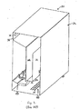
- Fig. 2 (also described previously) is an isometric view of the flame simulating assembly of the prior art of Fig. 1, drawn at a smaller scale;
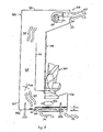
- Fig. 3 is a cross-section of a preferred embodiment of a flame simulating assembly of the invention, drawn at a larger scale;
- Fig. 4 is an isometric view of the flame simulating assembly of Fig. 3, drawn at a smaller scale;
- Fig. 5A is a schematic diagram of a preferred embodiment of a control circuit for providing an indication that a filter is obstructed to a predetermined extent
- Fig. 5B is a schematic diagram of an alternative embodiment of a control circuit for providing an indication that a filter is obstructed to a predetermined extent
- Fig. 5C is a schematic diagram of another alternative embodiment of a control circuit for providing an indication that a filter is obstructed to a predetermined extent
- Fig. 6 is a cross-section of an alternative embodiment of the flame simulating assembly of the invention.
- Fig. 7 is an isometric view of the flame simulating assembly of Fig. 6, drawn at a smaller scale;
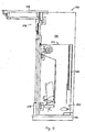
- Fig. 8 is a cross-section of an alternative embodiment of the flame simulating assembly of the invention, drawn at a larger scale;
- Fig. 9 is a cross-section of another alternative embodiment of the flame simulating assembly of the invention.
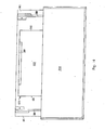
- Fig. 10 is a front view of the alternative embodiments of the invention shown in Figs. 8 and 9, drawn at a smaller scale;
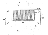
- Fig. 11 is a bottom view of the alternative embodiments of the invention shown in Figs 8 and 9;
- Fig. 12 is a cross-section of another alternative embodiment of the flame simulating assembly of the invention, in which a mantel portion of the flame simulating assembly is in a closed position, drawn at a smaller scale;
- Fig. 13 is a cross-section of the flame simulating assembly in which the mantel portion is in an open position
- Fig. 14 is an isometric view of the flame simulating assembly of Fig. 13, drawn at a smaller scale;
- Fig. 15 is another isometric view of the flame simulating assembly of Fig. 13, drawn at a smaller scale;
- Fig. 16 is a top view of the flame simulating assembly of Fig. 13, drawn at a larger scale.
- the flame simulating assembly 120 preferably includes a housing 122 with a top panel 123, two or more side panels 125 supporting the top panel 123, a back panel 127 connecting the side panels 125, and one or more front panels 134 positioned substantially opposite to the back panel 127.
- the flame simulating assembly also includes a simulated fuel bed 126 disposed in the housing 122 and a screen 124 positioned behind the simulated fuel bed 126, and the screen 124 has a front surface 129 disposed adjacent to the simulated fuel bed.
- the flame simulating assembly 120 additionally includes a flame image subassembly 150 for providing images of flames on the front surface 129 of the screen 124, as will be described.
- the screen 124, the housing 122 and the simulated fuel bed 126 delimit an internal chamber 128.
- the flame simulating assembly 120 also includes a fan 130 positioned to generate an air flow through the chamber 128 from one or more intake apertures 140, through which air is drawn into the chamber 128, to one or more exit apertures 136, through which the air exits the chamber 128.
- the flame simulating assembly 120 also includes one or more air filters 160 for filtering at least part of the air in the air flow through the internal chamber 128.
- the air filter 160 is positioned to filter the air in the air flow before the air enters the chamber 128.
- the flame simulating assembly 120 additionally includes one or more heating elements 132 for heating the air in the air flow before the air exits the chamber 128.
- the exit apertures 136 are preferably located in the front panel 134, also as shown in Fig. 3.
- the intake apertures 140 are preferably positioned in the back panel 127.
- the air filter 160 is positioned immediately in front of the intake apertures 140 in the preferred embodiment.
- the air filter 160 is preferably mounted in a frame 161 therefor which is positioned on the back panel 127.
- a seal (not shown) is provided between the air filter 160 and the frame 161, to provide a substantially airtight seal.
- a seal, or sealing element could be positioned in the frame 161 and/or included in the filter I60.
- FIG. 3 shows that ambient air (schematically represented by arrows 131) is drawn towards the intake apertures 140, through the air filter 160, and through the chamber 128 (as represented schematically by arrows 133 and 135).
- the air flow generated by the fan 130 results in the air in the air flow exiting the chamber 128 through exit apertures 136, as represented schematically by arrows 137.
- the air filter 160 is for removing contaminants in the air flow from the air.
- more than one air filter may be used together.
- a charcoal filter for odors
- pre-filter to remove larger particles
- filter with smaller holes in it to remove smaller particles.
- air filtration systems can include chemical and other systems for filtering air, as well as particulate filtration systems.
- references to the "air filter” will be understood to include a single filter and any of the foregoing types of air filtration systems.
- the housing is preferably constructed of panels of sheet metal which are fastened together using any suitable means.
- the housing is used to form part of a plenum (i.e., the internal chamber 128), the housing is manufaactured to be substantially airtight (i.e.. except for the intake and exit apertures), at least in the portions of the housing which delimit part of the internal chamber 128.
- the other components of the flame simulating assembly 120 which also delimit the internal chamber 128, i.e., the screen 124 and the simulated fuel bed 126, are preferably mounted in the housing 122 so that substantially airtight seals are formed between the housing, the screen 124 and the simulated fuel bed 126.
- Such sealing can be effected by any suitable means, including caulking with a suitable sealant, or using gaskets.
- the function of the sealing elements is to direct, or guide, the air in the air flow so that, in the preferred embodiment, virtually all of the air in the air flow is directed through the filter (i.e.. the air filtration system).
- the filter i.e.. the air filtration system.
- airbome contaminants and especially dust
- the sealing of the internal chamber i.e., excluding the intake and exit apertures
- some leakage around the sealing elements can be permitted, for acceptable functioning of the filtering system.
- the fan 130 is positioned proximal to the top panel 123 and the front panel 134, so that the air flow which is generated through the internal chamber 128 exits the internal chamber 128 above the screen 124, though the exit apertures 136 in the front panel 134.
- the air filter 160 (i.e., the operational area of the filter) is as large as possible, in order to facilitate efficient filtering of the air which passes through the filter 160. Because the filter 160 covers a relatively large area, the filter 160 can have a plurality of relatively small holes in it through which the air is drawn, however, with a relatively low pressure gradient across the filter 160.
- the air filter 160 is preferably a standard size particle filtering system, such as a filter 20 inches in height by approximately 20 inches in width by approximately one inch in thickness.
- the air filter 160 is an electrostatically charged filter, because an electrostatically charged filter operating with a relatively lower pressure drop across the filter is nevertheless generally as effective as a non-electrostatic filter operating with a higher pressure drop across it.
- the holes in the air filter 160 are relatively small, so that the filter can accumulate relatively small particulates.
- the intake apertures 140 are preferably distributed over an area of the back panel 127 which has approximately the same dimensions overall as the operative part of the air filter 160.
- the filter 160 tends to become obstructed after usage over a period of time, as particulates accumulate on the filter 160 and gradually build up to obstruct or close the holes in the filter 160. Because of this, the filter 160 has to be removed from the flame simulating assembly 120 from time to time, for maintenance. For example, depending on the type of filter, the air filter may be replaced by a new air filter. However, if the air filter is of a type which is to be cleaned, rather than replaced, then the air filter is cleaned.
- the flame simulating assembly 120 preferably includes a thermal switch (or control device) 162 (Fig. 5) positioned proximal to the heating element 132 (Fig. 3).
- the thermal switch 162 is adapted to cause an alerting device (preferably, an electric lamp) 164 to be energized upon the thermal switch sensing a predetermined temperaftue (or a higher temperature) in the air in the air flow.
- an alerting device preferably, an electric lamp
- thermal switch 162 and the electric lamp 164 are connected in series in a control circuit 166.
- the circuit 166 is connected (in parallel) to other circuits 168, 170, 172 included in the flame simulating assembly 120, also as shown in Fig. 5.
- the other circuits 168, 170, and 172 are required for the operation of other aspects of the flame simulating assembly 120, as is known in the art.
- the thermal switch (or control device) 162 includes one or more sensors for sensing (i.e., measuring) a temperature of the air in the air flow as the air exits the heating elements 132.
- the control circuit 166 operatively connects the sensors to the lamp for activating the lamp 164 when the measured temperature of the air in the air flow is at the predetermined temperature, or at a temperature greater than the predetermined temperature.
- the rate of flow of the air through the heating elements 132 decreases.
- the temperature of the air exiting the heating elements 132 quickly rises, becoming much hotter than the temperature of the air exiting the heating elements 132 under normal operating conditions.
- the thermal switch 162 which (in the preferred, embodiment) is normally open, closes when the predetermined temperature is reached, thereby completing the control circuit 166, and causing current to flow through the electric lamp 164. As is known in the art, the thermal switch remains closed until a reset button .is operated, regardless of the temperature of the air in the air flow after the thermal switch has closed.
- the electric lamp 164 preferably is mounted in a position where it is easily viewed by a user (not shown), such as in a control panel (not shown) mounted on the flame simulating assembly. Accordingly, upon activation of the electric lamp 164, the user is thereby alerted that the air filter 160 should be replaced. It will be appreciated that, instead of the electric lamp 164, any other suitable alerting device, such as a device for emitting an audible warning, could be used.
- control device can include an air flow meter (Figs. 5B and 5C) included in an alternative embodiment of the control circuit.
- Figs. 5B and 5C have the advantage that a sensor is monitoring the flow rate of the air flow in the absence of operation of the heating elements, this embodiment has the disadvantage (relative to the thermal switch) that the air flow meter components are slightly more complex than the components used in the thermal switch embodiment.
- an air flow meter 182 is adapted to sense a flow rate of the air flow and is included in a control circuit 183 (Fig. 5B).
- the control circuit 183 preferably includes an alerting device 184 to which the air flow meter 182 is operatively connected, so that a decrease in the flow rate of the air flow to a predetermined flow rate (or below) results in activation of the alerting device 184.
- the air flow meter 182 includes a Pitot tube 186 which is operatively connected to the alerting device 184 by a microelectronic component (or components) 188, as is known in the art.
- the Pitot tube has an inner tube (not shown) and an outer tube (not shown) bent into an L shape, and the inner tube is open at an end 190 directed upstream. Accordingly, the end 190 of the Pitot tube 186 is positioned appropriately in the air flow, so that the flow rate of the air flow is sensed by the Pitot tube 186,
- the control circuit 183 is electrically connected to the fireplace circuits (not shown in Fig. 5B) at terminals 191 of the control circuit 183, as is known in the art.
- FIG. 5C An alternative air flow meter 192, included in another alternative embodiment of a control circuit 193, is schematically illustrated in Fig. 5C.
- the air flow meter 192 includes a mechanical velocity meter 194 and an alerting device 195, the mechanical meter 194 and the alerting device 195 being operatively connected by a microelectronic component (or components) 196, as is known in the art.
- the mechanical meter 194 is positioned in the air flow, and is adapted to sense the rate of flow of the air flow. If the rate of flow decreases to a predetermined flow rate (or below), the alerting device 195 is activated.
- the alerting device 195 is an electric lamp.
- the control circuit 193 is electrically connected to the fireplace circuit(s) at terminals 198.
- the flame image subassembly 150 includes one or more light sources 152, a flicker element 154, and a flame effect element 156 (Fig. 3).
- the arrangement of the Same image subassembly 150 and its operation are generally as described in U.S. Patent No. 5,642,580 (Hess et al.), the entire specification of which is hereby incorporated herein by reference. It will be understood that the structures supporting and positioning the light source 152 and the flicker element 154 are known, and not included in Fig. 3 for clarity of illustration.
- the reflected light which is thus directed is also caused to flicker by the flicker element 154 because the flicker element 154 includes a plurality of reflective strips 157 which are rotated about an axis 158.
- the reflective strips 157 are arranged so that they appear to reflect light from the light source 152 intermittently,to mimic the flicketing light produced by a fire.
- the flame effect element 154 is preferably made of sheet metal, with an outline of flames 159 (Fig. 4) cut out of the sheet metal.
- the flame effect element 154 is positioned between the flicker element 152 and the back surface 155 of the screen 124.
- the flickering light which is directed towards the back surface 155 of the screen 124 is configured by the flame effect element 154 so that the images of flames are directed onto the back surface 155 of the screen 124.
- the structure of the screen 124 is preferably as described in U.S. Patent No. 5,642,580 (Hess et al.), or as described in U.S. Patent No. 6,363,636 (Hess et at), the entire specification of which is hereby incorporated herein by reference. Accordingly, one or more images of flames is provided at the front surface 129 of the screen 124 by the flame image subassembly 150.
- the images of flames provided by the flame image subassembly 150 appear to an observer (not shown) to be emanating from the simulated fuel bed 126.
- the illusion is enhanced when the front surface 129 is at least partially specularly reflective, as described in U.S. Patent No. 5,642,580 (Hess et al.).
- the images of flames could be provided by other known flame image subassemblies.
- the flame simulating assembly included in the flame simulating assembly 150 could include the components needed to provide images of flames in- accordance with any of the various methods disclosed in U.S. Patent No. 4,965,707 (Butterfield) or in GB- 2 242 737 (Shute).
- the images of flames could be provided via motion pictures of flames, as disclosed in co-pending U.S. patent application no. 11/038,118 filed on January 21, 2005, the entire specification of which is hereby incorporated herein by reference.
- ambient air is drawn by the fan 130 from the premises in which the flame simulating assembly 120 is located into the internal chamber 128 through the inlet aperhues 140, as indicated by arrows 131 (Fig. 3).
- the air is drawn through the internal chamber (as indicated by arrows 133 and 135) and through the fan 130 and the heating elements 132, to exit the internal chamber 128 through the exit apertures 136 (as indicated by arrows 137).
- the fan 130 can be operated independently of the heating elements 132. It will be understood that the fan 130 could "pull" or "push" the air in the air flow.
- the air filter When, as in the preferred embodiment, the air filter is mounted in the back panel, the air filter can have a relatively large operational area. This enables the filter to filter the air in the air flow relatively efficiently (i.e., at a relatively high flow rate) a relatively low pressure drop is provided across the filter.
- FIG. 6 -16 Additional embodiments of the invention are shown in Figs. 6 - 16.
- elements are numbered so as to correspond to like elements shown in Figs. 3 and 4.
- the flame simulating assembly 220 includes a flame image subassembly 250 which differs from the flame image subassembly 150 shown in Fig. 3.
- the flame image subassembly 250 light from a light source 252 is reflected by a nicker element 254 towards a flame effect clement 256 which has, on a front surface 257 thereof an outline of flames in a reflective material or finish (not shown) which reflects the flickering light towards a back surface 255 of a screen 224, to provide an image of flames at a front surface of the screen 224.
- the flame simulating assembly 220 additionally includes a simulated fuel bed 226 which is positioned adjacent to the front surface 229 of the screen 224, so that the images of flames produced by the flame image subassembly 250 appear to be emanating from the simulated fuel bed 226.
- the flame simulating assembly 220 includes a housing 222 with a top panel 223, two or more side panels 225 supporting the top panel 223, a back panel 227 connecting the side panels 225, and one or more front panels 234 positioned substantially opposite to the back panel 227.
- the screen 224, the housing 222 and the simulated fuel bed 226 delimit an internal chamber 228.
- the flame simulating assembly 220 also includes a fan 230 positioned to provide an air flow through the chamber 228 from one or more intake apertures 240, through which air is drawn into the chamber 228, to one or more exit apertures 236, through which the air exits the chamber 228.
- the flame simulating assembly additionally includes an air filter chamber 260 for filtering at least part of the air in the air flow through the internal chamber 228.
- the air filter 260 is positioned to filter the air in the air flow before the air exits the chamber 228. It is also preferred that the flame simulating assembly 220 includes one or more heating elements 232 for heating the air in the air flow before the air exits the chamber 228.
- the intake apertures 240 are positioned in the back panel 227, and the exit apertures 236 are positioned in the front panel 234.
- the air filter 260 is positioned immediately in front of the intake apertures 240, mounted in a frame 261 therefor.
- Ambient air (schematically represented by arrows 231) is drawn towards the intake apertures 240 and, through the air filter 260, and through the chamber 228 (as represented schematically by arrows 233 and 235).
- the air flow generated by the fan 130 results in the air in the air flow exiting the chamber 228 through the exit apertures 236, as represented schematically by arrows 237.
- FIG. 8 An alternative embodiment of a flame simulating assembly 320 of the invention is disclosed in Figs. 8, 10, and II.
- an air filter 360 is mounted on a bottom panel 342 of a housing 322 in a frame 361.
- the frame 361 preferably extends below the bottom panel 342 because it is necessary to allow space inside the flame simulating assembly 320 for components of a flame image subassembly 350 (i.e., a light source 352) above the bottom panel 342 and below a screen 324 and a simulated ember bed 326.
- a flame image subassembly 350 i.e., a light source 352
- the flame simulating assembly 320 includes a housing 322 which includes the bottom panel 342, a back panel 327 extending upwardly from the bottom panel 342, side panels 325 (Fig. 10) connected to each other by the bottom panel 342 and the back wall 327, a top panel 323 at the top of the side panels 325, and one or more front parts 334 positioned opposite to the back panel 327.
- the front parts 334 include a lower front part 370 positioned proximal to the bottom panel 342 and an upper front part 371 positioned proximal to the top panel 323.
- An internal chamber 328 is delimited by the housing 322, the screen 324, and the simulated fuel bed 326.
- the housing 322 also preferably includes feet 368 to support the bottom panel 342 above the floor (not shown), so that ambient air can flow into the internal chamber 328 from the premises.
- the bottom panel 342 has one or more intake apertures 340 positioned in it through which air is drawn by a fan 330 from the premises in which the flame simulating assembly 320 is located (schematically represented by arrows 331).
- the frame 361 for the filter 360 can be positioned substantially in an aperture 340 in the bottom panel 342.
- the fan 330 also drawn the air through the internal chamber 328 (as represented by arrows 333, 335) towards the fan 330, and the air is subsequently pushed by the fan 330 through exit apertures 336 out of the internal chamber 328.
- the air filter frame 361 preferably extends to the lower front part 370. Preferably, this permits relatively easy removal of the air filter 360 from the frame 361, by sliding the filter 360 fornvardly (i.e., in the direction of arrow "A" in Fig. 8).
- the filter 360 can be placed in the frame 361 by pushing the filter backwardly (i.e., in the direction of arrow "B" in Fig. 8).
- the filter 360 is preferably securely positioned in the frame 361 by a latching mechanism or any other suitable mechanism, as is known in the art.
- the frame 361 is also shown in Fig. 11 to extend to the front panel 371.
- arrows "A" and “B” are also shown in Fig. 11, to indicate the direction in which the filter 360 is moved when it is to be removed and the direction in which the filter 360 is moved when it is to be installed, respectively.
- the access from the front which is provided in the flame simulating assembly 320 is generally more convenient than the access to the filter which is provided in the embodiments of the flame simulating assembly (120, 220) in which the air filter (160, 260) is mounted on the back panel (127, 227).
- the air filter 360 is generally not as large as the air filter which is positioned in the back panel
- the bottom-mounted filter is typically a size such as approximately 20 inches by approximately 10 inches by 1 inch which is standard, and readily available from a variety of manufacturers.
- a larger operative area of an air filter is generally advantageous because a relatively large air flow volume can be provided through relatively small holes in the filter with a relatively low pressure differential across the filter.
- access to the bottom-mounted filter is relatively convenient
- a flame simulating assembly 420 includes a bottom-mounted filter 460 and a flame image subassembly 450 similar to the flame image subassembly 250.
- the flame image subassembly 450 includes a flame effect element 456 with a reflective portion 459 shaped to resemble flames, similar to the flame effect element 256 shown in Fig. 6.
- a front elevation view of the flame simulating assembly 420 also would be as shown in Fig. 10.
- Fig. 10 is an illustration of a front elevation view of the flame simulating assembly 320 also shown in Fig. 8.
- a bottom elevation view of the flame simulating assembly 420 would be as shown in Fig. 11.
- FIG. 12 Another alternative embodiment 520 of a flame simulating assembly is shown in Figs. 12 -16.
- the flame simulating assembly 520 includes an exterior subassembly 572 enclosing at least a portion of a housing 522 and generally including a mantel portion 574, a front portion 578, and side walls 580 (Figs. 14, 15).
- the flame simulating assembly 520 also includes a bottom portion 581 (Fig. 12).
- the exterior subassembly 572 comprises a "trim" package resembling a mantel and other decorative parts of an actual fireplace, which is provided to enhance the simulation effect of the flame simulating assembly.
- the exterior subassembly 572 can be made of wood, wood veneer, or any other suitable material, and provided with a suitable finish.
- the exterior subassembly 572 does not include a back wall, unless needed in a particular application.
- the mantel portion 574 is movable relative to the housing 522 between a closed position (Fig. 12), in which an air filter 560 is inaccessible because it is covered by the mantel portion 574, and an open position (Figs. 13 - 16), in which the air filter 560 is accessible because the mantel portion 574 has been moved forwardly.
- a closed position Fig. 12
- an open position Figs. 13 - 16
- the air filter 560 is accessible because the mantel portion 574 has been moved forwardly.
Landscapes
- Engineering & Computer Science (AREA)
- Chemical & Material Sciences (AREA)
- Combustion & Propulsion (AREA)
- Mechanical Engineering (AREA)
- General Engineering & Computer Science (AREA)
- Projection Apparatus (AREA)
- Direct Air Heating By Heater Or Combustion Gas (AREA)
- Filtering Of Dispersed Particles In Gases (AREA)
- Filtering Materials (AREA)
- Investigating Or Analyzing Materials Using Thermal Means (AREA)
Applications Claiming Priority (1)
| Application Number | Priority Date | Filing Date | Title |
|---|---|---|---|
| US11/060,398 US20060188831A1 (en) | 2005-02-18 | 2005-02-18 | Flame simulating assembly including an air filter |
Publications (2)
| Publication Number | Publication Date |
|---|---|
| EP1703210A1 true EP1703210A1 (de) | 2006-09-20 |
| EP1703210B1 EP1703210B1 (de) | 2009-03-25 |
Family
ID=36580415
Family Applications (1)
| Application Number | Title | Priority Date | Filing Date |
|---|---|---|---|
| EP06075337A Expired - Lifetime EP1703210B1 (de) | 2005-02-18 | 2006-02-15 | Vorrichtung zum Simulieren von Flammen mit einem Luftfilter |
Country Status (6)
| Country | Link |
|---|---|
| US (1) | US20060188831A1 (de) |
| EP (1) | EP1703210B1 (de) |
| CN (1) | CN1822073B (de) |
| AT (1) | ATE426780T1 (de) |
| CA (1) | CA2533260A1 (de) |
| DE (1) | DE602006005855D1 (de) |
Cited By (3)
| Publication number | Priority date | Publication date | Assignee | Title |
|---|---|---|---|---|
| US9068706B2 (en) | 2012-03-07 | 2015-06-30 | Winvic Sales Inc. | Electronic luminary device with simulated flame |
| US10352517B2 (en) | 2017-09-07 | 2019-07-16 | Sterno Home Inc. | Artificial candle with moveable projection screen position |
| EP3569931B1 (de) | 2018-05-16 | 2022-03-16 | Foshan city Tonghui Electronic Fireplace Ltd. | Flammen/rauch-simulation |
Families Citing this family (30)
| Publication number | Priority date | Publication date | Assignee | Title |
|---|---|---|---|---|
| CA2357182C (en) * | 2001-09-12 | 2009-01-06 | Dimplex North America Limited | Flame simulating assembly |
| US7673408B2 (en) * | 2004-01-20 | 2010-03-09 | Dimplex North America Limited | Flame simulating assembly |
| US7770312B2 (en) * | 2004-01-20 | 2010-08-10 | Dimplex North America Limited | Flame stimulating assembly |
| US20060101681A1 (en) | 2004-11-17 | 2006-05-18 | Dimplex North America Limited | Flame simulating assembly |
| US20070068924A1 (en) * | 2005-09-28 | 2007-03-29 | Hearth & Home Technologies, Inc. | Virtual hearth design system |
| US20070224561A1 (en) * | 2006-03-08 | 2007-09-27 | Dimplex North America Limited | Flame simulating assembly |
| US7826727B2 (en) * | 2006-05-05 | 2010-11-02 | Twin-Star International, Inc. | Electric fireplace |
| US7373743B1 (en) | 2007-03-14 | 2008-05-20 | Dimplex North America Limited | Flame simulating assembly |
| US8347534B2 (en) * | 2007-07-09 | 2013-01-08 | Ruiz Iraldo F | Recirculating levitated beads fountain display apparatus |
| CA2644246A1 (en) * | 2007-11-20 | 2009-05-20 | Twin Star International, Inc. | Electric fireplace |
| USD616977S1 (en) | 2008-12-03 | 2010-06-01 | Twin-Star International Inc. | Fireplace insert |
| USD668748S1 (en) | 2009-07-07 | 2012-10-09 | Twin-Star International, Inc. | Electric fireplace |
| US8944877B2 (en) | 2010-05-28 | 2015-02-03 | Mattel, Inc. | Action toy with jet pack |
| US8671600B2 (en) | 2012-03-29 | 2014-03-18 | Dongguan Song Wei Electric Technology Co., Ltd. | Electric fireplace |
| CN103405975A (zh) * | 2013-07-31 | 2013-11-27 | 李�诚 | 空气滤清器及其堵塞自动报警装置和方法 |
| US9709229B2 (en) | 2015-03-06 | 2017-07-18 | Dimplex North America Limited | Flame simulating assembly with flicker element including paddle elements |
| DK3220057T3 (da) | 2016-03-16 | 2019-07-08 | Glen Dimplex Americas Ltd | Flammesimuleringsenhed |
| US10495275B2 (en) | 2017-04-18 | 2019-12-03 | Glen Dimplex Americas Limited | Flame simulating assembly |
| USD837362S1 (en) | 2017-04-19 | 2019-01-01 | Glen Dimplex Americas Limited | Forked paddle element for an electric fireplace |
| US10584841B2 (en) | 2017-06-20 | 2020-03-10 | Living Style (B.V.I.) Limited | Flame simulating assembly with occluded shadow imaging wall |
| US11067238B2 (en) | 2017-06-20 | 2021-07-20 | Living Style (B.V.I.) Limited | Flame simulating assembly for simulated fireplaces including a reflecting light system |
| US11920747B2 (en) | 2017-06-20 | 2024-03-05 | Living Style (B.V.I.) Limited | Flame simulating assembly for simulated fireplaces including a reflecting light system |
| US10371333B2 (en) | 2017-06-20 | 2019-08-06 | Living Style (B.V.I) Limited | Flame simulating assembly for simulated fireplaces including an integrated flame screen and ember bed |
| CN109237521A (zh) * | 2017-07-10 | 2019-01-18 | 爱烙达股份有限公司 | 无烟囱壁炉安全结构 |
| US11002449B2 (en) | 2017-09-20 | 2021-05-11 | Pro-lroda Industries, Inc. | Smokeless safe combustion device |
| CN109323205A (zh) * | 2018-10-12 | 2019-02-12 | 南通亚泰蜡业工艺品有限公司 | 一种具有空气净化作用的电子蜡烛 |
| CN110567033A (zh) * | 2019-09-05 | 2019-12-13 | 莫洛尼家居用品(江苏)有限公司 | 一种diy场景组合仿真火电壁炉 |
| US11725791B1 (en) * | 2022-02-07 | 2023-08-15 | Rpg Brands | Faux fireplace with variable flame speed |
| US11725827B1 (en) * | 2022-02-07 | 2023-08-15 | Rpg Brands | Faux fireplace with synchronized flame crackling |
| US20230392793A1 (en) * | 2022-02-07 | 2023-12-07 | Modern Flames, Llc | Faux fireplace with user selectable video file |
Citations (9)
| Publication number | Priority date | Publication date | Assignee | Title |
|---|---|---|---|---|
| GB631594A (en) * | 1946-10-04 | 1949-11-07 | Frank Leslie Kerby James | Improvements in and relating to room heaters of the radiant type |
| GB928851A (en) * | 1959-02-10 | 1963-06-19 | Henry Mcdonald | An improved heating and ventilating unit |
| GB1212399A (en) * | 1968-03-25 | 1970-11-18 | Planet Jig & Tool Company Ltd | Improvements in and relating to domestic appliances including an humidifying unit |
| US4965707A (en) | 1989-02-10 | 1990-10-23 | Basic Engineering Ltd. | Apparatus for simulating flames |
| GB2242737A (en) | 1990-04-04 | 1991-10-09 | John Sydney Shute | Artificial fire units |
| US5642580A (en) | 1996-05-17 | 1997-07-01 | Dimplex North America Limited | Flame simulating assembley |
| US6363636B1 (en) | 1996-05-17 | 2002-04-02 | Dimplex North America Limited | Flame simulating assembly and components therefor |
| US6385881B1 (en) * | 1999-02-19 | 2002-05-14 | Dimplex North America Limited | Synchronized flicker device |
| US20020175215A1 (en) * | 2001-05-01 | 2002-11-28 | Webster Gary Stanton | Flame-effect heating apparatus |
Family Cites Families (73)
| Publication number | Priority date | Publication date | Assignee | Title |
|---|---|---|---|---|
| US566564A (en) * | 1896-08-25 | Mark w | ||
| US1586597A (en) * | 1923-01-25 | 1926-06-01 | Berry Herbert Henry | Imitation fire |
| US1531171A (en) * | 1924-03-07 | 1925-03-24 | Berry Herbert Henry | Electric fire |
| US1719622A (en) * | 1926-03-06 | 1929-07-02 | William E Price | Device for producing electric-light display effects |
| US1768284A (en) * | 1926-06-09 | 1930-06-24 | Berry Herbert Henry | Electric fire or radiator |
| US1827941A (en) * | 1928-04-06 | 1931-10-20 | Gross Henry John | Electric log |
| US1867740A (en) * | 1928-12-31 | 1932-07-19 | Walter W Guy | Electric fireplace |
| US1843279A (en) * | 1929-11-01 | 1932-02-02 | Gritt Ragsdale & Company Inc | Motion simulating device |
| US1824388A (en) * | 1930-02-11 | 1931-09-22 | Birch George Serge | Combination lamp and ventilator |
| US1809164A (en) * | 1930-11-28 | 1931-06-09 | Gritt Inc | Lamp for producing illuminated motion effects |
| US1992540A (en) * | 1932-07-09 | 1935-02-26 | George Henry Collins | Electric and other imitation fire |
| US2285535A (en) * | 1941-03-04 | 1942-06-09 | Schlett Otto | Fireplace display |
| US2708114A (en) * | 1954-05-19 | 1955-05-10 | Mastercrafters Clock & Radio C | Simulated fireplace |
| US3162847A (en) * | 1960-12-20 | 1964-12-22 | Chester A Huffman | Wind velocity alarm |
| GB1107092A (en) * | 1965-06-08 | 1968-03-20 | Frost & Company Ltd H | Improvements relating to electrical illumination devices |
| US3395476A (en) * | 1967-03-07 | 1968-08-06 | Frost & Company Ltd H | Electric illumination devices |
| US3395475A (en) * | 1967-03-07 | 1968-08-06 | Frost & Company Ltd H | Electrical illumination devices |
| GB1186655A (en) * | 1968-02-06 | 1970-04-02 | Frost & Company Ltd H | Electric Illumination Devices |
| BE789017A (nl) * | 1971-09-20 | 1973-03-20 | Meyer Fred Calif | Nagebootste open haard |
| US3952182A (en) * | 1974-01-25 | 1976-04-20 | Flanders Robert D | Instantaneous electric fluid heater |
| US3930490A (en) * | 1974-03-25 | 1976-01-06 | Lassy Carl O | Fireplace heater |
| US3978598A (en) * | 1975-01-16 | 1976-09-07 | Rose Bernard R | Apparatus for simulating an open fire |
| US4076011A (en) * | 1976-06-21 | 1978-02-28 | Roger Proulx | Warm air heating and fire-place system |
| US4573905A (en) * | 1984-11-13 | 1986-03-04 | Meyers Wayne E | Burner unit for fireplace simulation |
| US4890600A (en) * | 1988-10-26 | 1990-01-02 | Genesis Technology | Fireplace burning simulator unit |
| US5195820A (en) * | 1992-01-21 | 1993-03-23 | Superior Fireplace Company | Fireplace with simulated flames |
| US5648827A (en) * | 1995-06-22 | 1997-07-15 | Rockwell International Corporation | Backlighting system for liquid crystal displays having a non-planar fluorescent lamp |
| US6047489A (en) * | 1996-05-17 | 2000-04-11 | Dimplex North America Limited | Flame simulating assembly and components therefor |
| PL183547B1 (pl) * | 1996-04-30 | 2002-06-28 | Dimplex North America Ltd | Urządzenie symulujące płomienie |
| US20040181983A1 (en) * | 1996-05-17 | 2004-09-23 | Dimplex North America Limited | Flame simulating assembly |
| US6718665B2 (en) * | 1996-05-17 | 2004-04-13 | Dimplex North America Limited | Flame simulating assembly |
| US5826357A (en) * | 1996-07-08 | 1998-10-27 | Hechler; Duaine | Entertainment and fireplace assembly |
| GB2350887B (en) * | 1997-05-31 | 2001-10-24 | Burley Appliances Ltd | Apparatus for simulating flames |
| US5989128A (en) * | 1998-01-08 | 1999-11-23 | Universal Studios, Inc. | Flame simulation |
| US6129285A (en) * | 1998-08-11 | 2000-10-10 | Schafka; Mark Louis | System and method for air humidification |
| DE19856742C2 (de) * | 1998-12-09 | 2002-03-07 | Ewt Glen Electric Gmbh | Vorrichtung zur künstlichen Simulation eines Feuers |
| US6053165A (en) * | 1999-01-13 | 2000-04-25 | Heat-N-Glo Fireplace Products, Inc. | Simulated electric glowing embers for gas fireplaces |
| US6393207B1 (en) * | 1999-01-14 | 2002-05-21 | Cfm Majestic Inc. | Electric fireplace with light randomizer, filter and diffuser screen |
| GB2346686B (en) * | 1999-02-15 | 2002-11-13 | Unique Flame Light Company Ltd | Simulated flame device |
| JP3477128B2 (ja) * | 1999-11-30 | 2003-12-10 | 三菱電機株式会社 | 内燃機関のバルブタイミング制御装置 |
| US6615519B2 (en) * | 2000-08-29 | 2003-09-09 | Dimplex North America Limited | Flame simulating assembly |
| US6564485B1 (en) * | 2000-08-29 | 2003-05-20 | Dimplex North America Limited | Fire simulating assembly |
| JP3699655B2 (ja) * | 2001-02-01 | 2005-09-28 | 三菱電機株式会社 | 内燃機関のバルブタイミング制御装置 |
| US6880275B2 (en) * | 2001-05-16 | 2005-04-19 | Hon Technology Inc. | Lenticular fireplace |
| US20020174579A1 (en) * | 2001-05-22 | 2002-11-28 | Corry Arthur A. | Artificial log burning fireplace assembly |
| GB2376292B (en) * | 2001-06-06 | 2003-08-20 | Focal Point Fires Plc | Flame simulation apparatus |
| US20030041491A1 (en) * | 2001-08-28 | 2003-03-06 | Mix Devin Eugene | Flame simulation apparatus and methods |
| US20030049024A1 (en) * | 2001-09-07 | 2003-03-13 | Globaltec Distributors Ltd. | Electric fireplace perforated light-emitting rotator flame simulator |
| CA2357182C (en) * | 2001-09-12 | 2009-01-06 | Dimplex North America Limited | Flame simulating assembly |
| GB0123906D0 (en) * | 2001-10-05 | 2001-11-28 | Cfm Kinder Ltd | Fire assembly |
| US6601579B2 (en) * | 2001-11-13 | 2003-08-05 | Hon Technology Inc. | Indoor-outdoor fireplace |
| GB0200656D0 (en) * | 2002-01-14 | 2002-02-27 | Burley Appliances Ltd | Apparatus for simulating flames |
| US20030156828A1 (en) * | 2002-02-15 | 2003-08-21 | Jamieson Donald R. | Fireplace with simulated flame |
| US6736133B2 (en) * | 2002-04-09 | 2004-05-18 | Hon Technology Inc. | Air filtration and sterilization system for a fireplace |
| US6919884B2 (en) * | 2002-04-10 | 2005-07-19 | Hon Technology Inc. | Simulated fireplace including electronic display |
| CN2555085Y (zh) * | 2002-07-02 | 2003-06-11 | 周忠平 | 扁布袋除尘器除尘效率检测装置 |
| US6848441B2 (en) * | 2002-07-19 | 2005-02-01 | Hon Technology Inc. | Apparatus and method for cooling a surface of a fireplace |
| CA2499556C (en) * | 2002-09-19 | 2011-09-13 | Basic Holdings | Apparatus for providing a visual effect |
| US6944982B2 (en) * | 2002-09-27 | 2005-09-20 | Napoloen Systems And Developments Inc. | Flame simulating apparatus |
| JP4101625B2 (ja) * | 2002-12-03 | 2008-06-18 | 株式会社日立製作所 | 内燃機関の可変動弁制御装置 |
| CA2416741A1 (en) * | 2003-01-20 | 2004-07-20 | Kelly Stinson | Flame simulating assembly |
| US20040200471A1 (en) * | 2003-04-11 | 2004-10-14 | Rumens Kurt W. F. | Fireplace assembly cover panels |
| US20040264949A1 (en) * | 2003-06-27 | 2004-12-30 | David Deng | Fireplace |
| US20050097792A1 (en) * | 2003-11-06 | 2005-05-12 | Damir Naden | Apparatus and method for simulation of combustion effects in a fireplace |
| US7673408B2 (en) * | 2004-01-20 | 2010-03-09 | Dimplex North America Limited | Flame simulating assembly |
| US7770312B2 (en) * | 2004-01-20 | 2010-08-10 | Dimplex North America Limited | Flame stimulating assembly |
| US6993929B1 (en) * | 2004-08-05 | 2006-02-07 | Manitowoc Foodservice Companies, Inc. | Ice-making machine with contoured water curtain |
| US20060101681A1 (en) * | 2004-11-17 | 2006-05-18 | Dimplex North America Limited | Flame simulating assembly |
| US20060162198A1 (en) * | 2005-01-21 | 2006-07-27 | Dimplex North America Limited | Flame simulating assembly |
| US20060242870A1 (en) * | 2005-02-08 | 2006-11-02 | Travis Industries, Inc. | Flame assembly for fireplace |
| US20060185664A1 (en) * | 2005-02-22 | 2006-08-24 | Butler Gary L | Burner system incorporating flame and light |
| US20070224561A1 (en) * | 2006-03-08 | 2007-09-27 | Dimplex North America Limited | Flame simulating assembly |
| US7373743B1 (en) * | 2007-03-14 | 2008-05-20 | Dimplex North America Limited | Flame simulating assembly |
-
2005
- 2005-02-18 US US11/060,398 patent/US20060188831A1/en not_active Abandoned
-
2006
- 2006-01-19 CA CA002533260A patent/CA2533260A1/en not_active Abandoned
- 2006-02-15 AT AT06075337T patent/ATE426780T1/de not_active IP Right Cessation
- 2006-02-15 DE DE602006005855T patent/DE602006005855D1/de not_active Expired - Lifetime
- 2006-02-15 EP EP06075337A patent/EP1703210B1/de not_active Expired - Lifetime
- 2006-02-17 CN CN200610008599.9A patent/CN1822073B/zh not_active Expired - Fee Related
Patent Citations (9)
| Publication number | Priority date | Publication date | Assignee | Title |
|---|---|---|---|---|
| GB631594A (en) * | 1946-10-04 | 1949-11-07 | Frank Leslie Kerby James | Improvements in and relating to room heaters of the radiant type |
| GB928851A (en) * | 1959-02-10 | 1963-06-19 | Henry Mcdonald | An improved heating and ventilating unit |
| GB1212399A (en) * | 1968-03-25 | 1970-11-18 | Planet Jig & Tool Company Ltd | Improvements in and relating to domestic appliances including an humidifying unit |
| US4965707A (en) | 1989-02-10 | 1990-10-23 | Basic Engineering Ltd. | Apparatus for simulating flames |
| GB2242737A (en) | 1990-04-04 | 1991-10-09 | John Sydney Shute | Artificial fire units |
| US5642580A (en) | 1996-05-17 | 1997-07-01 | Dimplex North America Limited | Flame simulating assembley |
| US6363636B1 (en) | 1996-05-17 | 2002-04-02 | Dimplex North America Limited | Flame simulating assembly and components therefor |
| US6385881B1 (en) * | 1999-02-19 | 2002-05-14 | Dimplex North America Limited | Synchronized flicker device |
| US20020175215A1 (en) * | 2001-05-01 | 2002-11-28 | Webster Gary Stanton | Flame-effect heating apparatus |
Cited By (8)
| Publication number | Priority date | Publication date | Assignee | Title |
|---|---|---|---|---|
| US9068706B2 (en) | 2012-03-07 | 2015-06-30 | Winvic Sales Inc. | Electronic luminary device with simulated flame |
| US9447937B2 (en) | 2012-03-07 | 2016-09-20 | Nii Northern International Inc. | Electronic luminary device with simulated flame |
| US10024507B2 (en) | 2012-03-07 | 2018-07-17 | Sterno Home Inc. | Electronic luminary device with simulated flame |
| US10352517B2 (en) | 2017-09-07 | 2019-07-16 | Sterno Home Inc. | Artificial candle with moveable projection screen position |
| US10578264B2 (en) | 2017-09-07 | 2020-03-03 | Sterno Home Inc. | Artificial candle with moveable projection screen position |
| US10788179B2 (en) | 2017-09-07 | 2020-09-29 | Sterno Home Inc. | Artificial candle with moveable projection screen position |
| US10808899B2 (en) | 2017-09-07 | 2020-10-20 | Sterno Home Inc. | Artificial candle with moveable projection screen position |
| EP3569931B1 (de) | 2018-05-16 | 2022-03-16 | Foshan city Tonghui Electronic Fireplace Ltd. | Flammen/rauch-simulation |
Also Published As
| Publication number | Publication date |
|---|---|
| CN1822073B (zh) | 2010-12-08 |
| DE602006005855D1 (de) | 2009-05-07 |
| ATE426780T1 (de) | 2009-04-15 |
| CA2533260A1 (en) | 2006-08-18 |
| EP1703210B1 (de) | 2009-03-25 |
| US20060188831A1 (en) | 2006-08-24 |
| CN1822073A (zh) | 2006-08-23 |
Similar Documents
| Publication | Publication Date | Title |
|---|---|---|
| EP1703210B1 (de) | Vorrichtung zum Simulieren von Flammen mit einem Luftfilter | |
| US7699051B2 (en) | Range hood | |
| RU2407952C2 (ru) | Искусственный камин | |
| RU2352825C1 (ru) | Устройство для прохождения воздуха с элементом управления | |
| JP2008057968A (ja) | ダクトにハウジングを取り付ける方法およびハウジング機構 | |
| US20070062513A1 (en) | Cooking system with ventilator and blower | |
| KR101611028B1 (ko) | 공기 청정기 | |
| US7134221B2 (en) | Method of detecting lint | |
| US20120008100A1 (en) | Dustproof structure of image generation device, and projection display device | |
| JP2011112251A (ja) | 室内循環式レンジフード | |
| US20050063685A1 (en) | Space heater | |
| KR102321002B1 (ko) | 공기청정기 및 그 제어방법 | |
| JPH08152242A (ja) | エアフィルタ交換装置 | |
| JP6024925B2 (ja) | 集塵装置および集塵装置における火災検出方法 | |
| US12140317B2 (en) | Recirculation grill with mobile platform | |
| JP5334778B2 (ja) | 火災警報器の試験設備 | |
| CA2616040A1 (en) | Simulated fire apparatus for chimneys | |
| JP3308424B2 (ja) | 調理場用換気扇 | |
| CN220455936U (zh) | 一种安防设备销售用性能测试设备 | |
| JP4032195B2 (ja) | 局所清浄型空気清浄機 | |
| US20070060034A1 (en) | Gaming machine smoke control systems and processes | |
| JPS6349637Y2 (de) | ||
| CN118781737A (zh) | 智能烟雾感应防火系统 | |
| JP2010270987A (ja) | ガスファンヒータ | |
| JP2007032988A (ja) | 煙道炎検知システム |
Legal Events
| Date | Code | Title | Description |
|---|---|---|---|
| PUAI | Public reference made under article 153(3) epc to a published international application that has entered the european phase |
Free format text: ORIGINAL CODE: 0009012 |
|
| AK | Designated contracting states |
Kind code of ref document: A1 Designated state(s): AT BE BG CH CY CZ DE DK EE ES FI FR GB GR HU IE IS IT LI LT LU LV MC NL PL PT RO SE SI SK TR |
|
| AX | Request for extension of the european patent |
Extension state: AL BA HR MK YU |
|
| 17P | Request for examination filed |
Effective date: 20070131 |
|
| AKX | Designation fees paid |
Designated state(s): AT BE BG CH CY CZ DE DK EE ES FI FR GB GR HU IE IS IT LI LT LU LV MC NL PL PT RO SE SI SK TR |
|
| 17Q | First examination report despatched |
Effective date: 20070509 |
|
| GRAP | Despatch of communication of intention to grant a patent |
Free format text: ORIGINAL CODE: EPIDOSNIGR1 |
|
| GRAS | Grant fee paid |
Free format text: ORIGINAL CODE: EPIDOSNIGR3 |
|
| GRAA | (expected) grant |
Free format text: ORIGINAL CODE: 0009210 |
|
| AK | Designated contracting states |
Kind code of ref document: B1 Designated state(s): AT BE BG CH CY CZ DE DK EE ES FI FR GB GR HU IE IS IT LI LT LU LV MC NL PL PT RO SE SI SK TR |
|
| REG | Reference to a national code |
Ref country code: GB Ref legal event code: FG4D |
|
| REG | Reference to a national code |
Ref country code: CH Ref legal event code: EP |
|
| REG | Reference to a national code |
Ref country code: IE Ref legal event code: FG4D |
|
| REF | Corresponds to: |
Ref document number: 602006005855 Country of ref document: DE Date of ref document: 20090507 Kind code of ref document: P |
|
| PG25 | Lapsed in a contracting state [announced via postgrant information from national office to epo] |
Ref country code: SI Free format text: LAPSE BECAUSE OF FAILURE TO SUBMIT A TRANSLATION OF THE DESCRIPTION OR TO PAY THE FEE WITHIN THE PRESCRIBED TIME-LIMIT Effective date: 20090325 Ref country code: LT Free format text: LAPSE BECAUSE OF FAILURE TO SUBMIT A TRANSLATION OF THE DESCRIPTION OR TO PAY THE FEE WITHIN THE PRESCRIBED TIME-LIMIT Effective date: 20090325 Ref country code: FI Free format text: LAPSE BECAUSE OF FAILURE TO SUBMIT A TRANSLATION OF THE DESCRIPTION OR TO PAY THE FEE WITHIN THE PRESCRIBED TIME-LIMIT Effective date: 20090325 |
|
| PG25 | Lapsed in a contracting state [announced via postgrant information from national office to epo] |
Ref country code: SE Free format text: LAPSE BECAUSE OF FAILURE TO SUBMIT A TRANSLATION OF THE DESCRIPTION OR TO PAY THE FEE WITHIN THE PRESCRIBED TIME-LIMIT Effective date: 20090625 Ref country code: PL Free format text: LAPSE BECAUSE OF FAILURE TO SUBMIT A TRANSLATION OF THE DESCRIPTION OR TO PAY THE FEE WITHIN THE PRESCRIBED TIME-LIMIT Effective date: 20090325 Ref country code: AT Free format text: LAPSE BECAUSE OF FAILURE TO SUBMIT A TRANSLATION OF THE DESCRIPTION OR TO PAY THE FEE WITHIN THE PRESCRIBED TIME-LIMIT Effective date: 20090325 Ref country code: LV Free format text: LAPSE BECAUSE OF FAILURE TO SUBMIT A TRANSLATION OF THE DESCRIPTION OR TO PAY THE FEE WITHIN THE PRESCRIBED TIME-LIMIT Effective date: 20090325 |
|
| PG25 | Lapsed in a contracting state [announced via postgrant information from national office to epo] |
Ref country code: CZ Free format text: LAPSE BECAUSE OF FAILURE TO SUBMIT A TRANSLATION OF THE DESCRIPTION OR TO PAY THE FEE WITHIN THE PRESCRIBED TIME-LIMIT Effective date: 20090325 Ref country code: ES Free format text: LAPSE BECAUSE OF FAILURE TO SUBMIT A TRANSLATION OF THE DESCRIPTION OR TO PAY THE FEE WITHIN THE PRESCRIBED TIME-LIMIT Effective date: 20090706 Ref country code: EE Free format text: LAPSE BECAUSE OF FAILURE TO SUBMIT A TRANSLATION OF THE DESCRIPTION OR TO PAY THE FEE WITHIN THE PRESCRIBED TIME-LIMIT Effective date: 20090325 Ref country code: PT Free format text: LAPSE BECAUSE OF FAILURE TO SUBMIT A TRANSLATION OF THE DESCRIPTION OR TO PAY THE FEE WITHIN THE PRESCRIBED TIME-LIMIT Effective date: 20090901 |
|
| PG25 | Lapsed in a contracting state [announced via postgrant information from national office to epo] |
Ref country code: RO Free format text: LAPSE BECAUSE OF FAILURE TO SUBMIT A TRANSLATION OF THE DESCRIPTION OR TO PAY THE FEE WITHIN THE PRESCRIBED TIME-LIMIT Effective date: 20090325 Ref country code: IS Free format text: LAPSE BECAUSE OF FAILURE TO SUBMIT A TRANSLATION OF THE DESCRIPTION OR TO PAY THE FEE WITHIN THE PRESCRIBED TIME-LIMIT Effective date: 20090725 Ref country code: SK Free format text: LAPSE BECAUSE OF FAILURE TO SUBMIT A TRANSLATION OF THE DESCRIPTION OR TO PAY THE FEE WITHIN THE PRESCRIBED TIME-LIMIT Effective date: 20090325 |
|
| PG25 | Lapsed in a contracting state [announced via postgrant information from national office to epo] |
Ref country code: DK Free format text: LAPSE BECAUSE OF FAILURE TO SUBMIT A TRANSLATION OF THE DESCRIPTION OR TO PAY THE FEE WITHIN THE PRESCRIBED TIME-LIMIT Effective date: 20090325 Ref country code: BG Free format text: LAPSE BECAUSE OF FAILURE TO SUBMIT A TRANSLATION OF THE DESCRIPTION OR TO PAY THE FEE WITHIN THE PRESCRIBED TIME-LIMIT Effective date: 20090625 |
|
| PLBE | No opposition filed within time limit |
Free format text: ORIGINAL CODE: 0009261 |
|
| STAA | Information on the status of an ep patent application or granted ep patent |
Free format text: STATUS: NO OPPOSITION FILED WITHIN TIME LIMIT |
|
| 26N | No opposition filed |
Effective date: 20091229 |
|
| BERE | Be: lapsed |
Owner name: DIMPLEX NORTH AMERICA LIMITED Effective date: 20100228 |
|
| REG | Reference to a national code |
Ref country code: NL Ref legal event code: V1 Effective date: 20100901 |
|
| REG | Reference to a national code |
Ref country code: CH Ref legal event code: PL |
|
| PG25 | Lapsed in a contracting state [announced via postgrant information from national office to epo] |
Ref country code: GR Free format text: LAPSE BECAUSE OF FAILURE TO SUBMIT A TRANSLATION OF THE DESCRIPTION OR TO PAY THE FEE WITHIN THE PRESCRIBED TIME-LIMIT Effective date: 20090626 Ref country code: CH Free format text: LAPSE BECAUSE OF NON-PAYMENT OF DUE FEES Effective date: 20100228 Ref country code: LI Free format text: LAPSE BECAUSE OF NON-PAYMENT OF DUE FEES Effective date: 20100228 Ref country code: MC Free format text: LAPSE BECAUSE OF NON-PAYMENT OF DUE FEES Effective date: 20100301 |
|
| PG25 | Lapsed in a contracting state [announced via postgrant information from national office to epo] |
Ref country code: NL Free format text: LAPSE BECAUSE OF NON-PAYMENT OF DUE FEES Effective date: 20100901 |
|
| PG25 | Lapsed in a contracting state [announced via postgrant information from national office to epo] |
Ref country code: BE Free format text: LAPSE BECAUSE OF NON-PAYMENT OF DUE FEES Effective date: 20100228 |
|
| PG25 | Lapsed in a contracting state [announced via postgrant information from national office to epo] |
Ref country code: IT Free format text: LAPSE BECAUSE OF NON-PAYMENT OF DUE FEES Effective date: 20100215 |
|
| PGFP | Annual fee paid to national office [announced via postgrant information from national office to epo] |
Ref country code: IE Payment date: 20110217 Year of fee payment: 6 |
|
| PGFP | Annual fee paid to national office [announced via postgrant information from national office to epo] |
Ref country code: FR Payment date: 20110302 Year of fee payment: 6 Ref country code: DE Payment date: 20110222 Year of fee payment: 6 |
|
| PGFP | Annual fee paid to national office [announced via postgrant information from national office to epo] |
Ref country code: GB Payment date: 20110202 Year of fee payment: 6 |
|
| PG25 | Lapsed in a contracting state [announced via postgrant information from national office to epo] |
Ref country code: CY Free format text: LAPSE BECAUSE OF FAILURE TO SUBMIT A TRANSLATION OF THE DESCRIPTION OR TO PAY THE FEE WITHIN THE PRESCRIBED TIME-LIMIT Effective date: 20090325 |
|
| PG25 | Lapsed in a contracting state [announced via postgrant information from national office to epo] |
Ref country code: HU Free format text: LAPSE BECAUSE OF FAILURE TO SUBMIT A TRANSLATION OF THE DESCRIPTION OR TO PAY THE FEE WITHIN THE PRESCRIBED TIME-LIMIT Effective date: 20090926 Ref country code: LU Free format text: LAPSE BECAUSE OF NON-PAYMENT OF DUE FEES Effective date: 20100215 |
|
| GBPC | Gb: european patent ceased through non-payment of renewal fee |
Effective date: 20120215 |
|
| PG25 | Lapsed in a contracting state [announced via postgrant information from national office to epo] |
Ref country code: TR Free format text: LAPSE BECAUSE OF FAILURE TO SUBMIT A TRANSLATION OF THE DESCRIPTION OR TO PAY THE FEE WITHIN THE PRESCRIBED TIME-LIMIT Effective date: 20090325 |
|
| REG | Reference to a national code |
Ref country code: IE Ref legal event code: MM4A |
|
| REG | Reference to a national code |
Ref country code: FR Ref legal event code: ST Effective date: 20121031 |
|
| REG | Reference to a national code |
Ref country code: DE Ref legal event code: R119 Ref document number: 602006005855 Country of ref document: DE Effective date: 20120901 |
|
| PG25 | Lapsed in a contracting state [announced via postgrant information from national office to epo] |
Ref country code: FR Free format text: LAPSE BECAUSE OF NON-PAYMENT OF DUE FEES Effective date: 20120229 Ref country code: IE Free format text: LAPSE BECAUSE OF NON-PAYMENT OF DUE FEES Effective date: 20120215 Ref country code: GB Free format text: LAPSE BECAUSE OF NON-PAYMENT OF DUE FEES Effective date: 20120215 |
|
| PG25 | Lapsed in a contracting state [announced via postgrant information from national office to epo] |
Ref country code: DE Free format text: LAPSE BECAUSE OF NON-PAYMENT OF DUE FEES Effective date: 20120901 |