EP1703228B1 - Ensemble pour installation de chauffage compacte - Google Patents
Ensemble pour installation de chauffage compacte Download PDFInfo
- Publication number
- EP1703228B1 EP1703228B1 EP05005571A EP05005571A EP1703228B1 EP 1703228 B1 EP1703228 B1 EP 1703228B1 EP 05005571 A EP05005571 A EP 05005571A EP 05005571 A EP05005571 A EP 05005571A EP 1703228 B1 EP1703228 B1 EP 1703228B1
- Authority
- EP
- European Patent Office
- Prior art keywords
- construction unit
- positive
- unit according
- fit element
- connection
- Prior art date
- Legal status (The legal status is an assumption and is not a legal conclusion. Google has not performed a legal analysis and makes no representation as to the accuracy of the status listed.)
- Expired - Lifetime
Links
- 238000010438 heat treatment Methods 0.000 title claims abstract description 23
- 238000009434 installation Methods 0.000 title claims 5
- 238000002347 injection Methods 0.000 claims abstract description 12
- 239000007924 injection Substances 0.000 claims abstract description 12
- 239000012530 fluid Substances 0.000 claims abstract description 3
- 238000010276 construction Methods 0.000 claims 22
- 238000001746 injection moulding Methods 0.000 claims 1
- 230000005540 biological transmission Effects 0.000 abstract description 2
- 230000002349 favourable effect Effects 0.000 description 3
- 238000003780 insertion Methods 0.000 description 3
- 230000037431 insertion Effects 0.000 description 3
- 238000013461 design Methods 0.000 description 2
- JEIPFZHSYJVQDO-UHFFFAOYSA-N iron(III) oxide Inorganic materials O=[Fe]O[Fe]=O JEIPFZHSYJVQDO-UHFFFAOYSA-N 0.000 description 2
- 238000000034 method Methods 0.000 description 2
- 230000001953 sensory effect Effects 0.000 description 2
- XLYOFNOQVPJJNP-UHFFFAOYSA-N water Substances O XLYOFNOQVPJJNP-UHFFFAOYSA-N 0.000 description 2
- 230000007547 defect Effects 0.000 description 1
- 238000010348 incorporation Methods 0.000 description 1
- 238000012423 maintenance Methods 0.000 description 1
- 238000012549 training Methods 0.000 description 1
- 238000013519 translation Methods 0.000 description 1
Images


Classifications
-
- F—MECHANICAL ENGINEERING; LIGHTING; HEATING; WEAPONS; BLASTING
- F24—HEATING; RANGES; VENTILATING
- F24H—FLUID HEATERS, e.g. WATER OR AIR HEATERS, HAVING HEAT-GENERATING MEANS, e.g. HEAT PUMPS, IN GENERAL
- F24H9/00—Details
- F24H9/14—Arrangements for connecting different sections, e.g. in water heaters
-
- F—MECHANICAL ENGINEERING; LIGHTING; HEATING; WEAPONS; BLASTING
- F24—HEATING; RANGES; VENTILATING
- F24H—FLUID HEATERS, e.g. WATER OR AIR HEATERS, HAVING HEAT-GENERATING MEANS, e.g. HEAT PUMPS, IN GENERAL
- F24H9/00—Details
- F24H9/14—Arrangements for connecting different sections, e.g. in water heaters
- F24H9/142—Connecting hydraulic components
Definitions
- the one or more positive locking elements are mounted in a translationally movable manner, so that they secure the connection in a bolt-like manner after the fluid-conducting connections have been plugged together.
- the transiatory movement of the form-locking elements or the form-locking element, if only one is provided advantageously transversely to the direction of insertion of the terminal, since particularly high forces are absorbed in this arrangement can, without the risk of loosening the Form gleichver connection is given.
- the drive wheel which causes the translational movement of the rack, part of a shaft which is rotatably mounted within the assembly.
- the drive wheel and shaft are advantageously integrally formed as a plastic injection molded part and preferably latched in a bearing receptacle of the assembly and rotatably mounted so that after inserting the rack in the unit provided on the linear guide which carries the drive wheel shaft can be inserted into the bearing receptacle, after which Drive connection between the drive wheel and rack is made.
- the receiving plate 11 forms part of the example attached to the wall chassis of the compact heating system, which is not shown here in detail.
- the connecting pieces 10 have on their underside a thread, via which they are connected in a conventional manner with the free ends of the stationary pipes.
- These nozzles have previously been inserted from above, so from the unit side of the connection plate 11 through oval recesses 14, so that they in the FIGS. 1 and 2 occupy the position shown, in which they rest with a flaky part on the top of the receiving plate 11, pass through the respective recess 14 with a positive-locking part and lying behind a groove, with which the connecting pieces 10 by means of a bracket, not shown, can be secured positively within the receiving plate 11 ,
- the assembly 1 which is then advantageously fully populated, lowered in the direction 12 with the line terminals 6 to 9. until the connecting pieces 10 sealingly engage in the line connections 6 to 9.
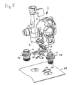
- Plate-shaped form-locking elements 15 pass through approximately T-shaped recesses 16 in the connection plate 11. These form-locking elements 15 are connected via a web to the back of a rack 17 and formed integrally therewith, such that a positive locking element 15 laterally projects beyond the web to two directions as this is based on the FIGS. 4 and 5 is visible.
- the shaft 22 with the drive wheel 23, the projection 26 and the molded tool holder 25 is integrally formed as a plastic injection molded part.
- This in Fig. 5 pointing in the plane of the drawing end is conical and longitudinally formed, so that this component in the corresponding circular recess 27 of the bearing holder 21 is inserted in such a way that it locks there after reaching its intended position according to the springing of the end-side divided area.
- the locking lug 28 ' is modified.
- the end of the rack 17 is wave-shaped, whereby on the one hand a greater travel of the locking lug 28 'is achieved and on the other hand at the end of a handle 29 is formed, which serves to release the latching connection, when the lock should be canceled, for example the unit 1 of the receiving plate 11 for the purpose of repair or maintenance to separate.
Landscapes
- Engineering & Computer Science (AREA)
- General Engineering & Computer Science (AREA)
- Chemical & Material Sciences (AREA)
- Thermal Sciences (AREA)
- Combustion & Propulsion (AREA)
- Mechanical Engineering (AREA)
- Physics & Mathematics (AREA)
- Injection Moulding Of Plastics Or The Like (AREA)
- Air-Conditioning For Vehicles (AREA)
- Pipe Accessories (AREA)
- Instantaneous Water Boilers, Portable Hot-Water Supply Apparatuses, And Control Of Portable Hot-Water Supply Apparatuses (AREA)
- Basic Packing Technique (AREA)
- Yarns And Mechanical Finishing Of Yarns Or Ropes (AREA)
- Resistance Heating (AREA)
Claims (14)
- Module pour une installation de chauffage compacte, qui comporte un boîtier moulé par injection (2, 3, 4) en une ou plusieurs parties, présentant au moins un raccord de conduite enfichable (6, 7, 8, 9) vers une conduite de fluide (10) fixe, et comportant des moyens permettant de bloquer par complémentarité de forme la connexion enfichable et/ou le module (1) à l'intérieur de l'installation de chauffage compacte, caractérisé en ce que les moyens de blocage présentent au moins un élément à liaison de forme (15) logé de façon mobile au niveau du module (1).
- Module selon la revendication 1, caractérisé en ce que dans ou au niveau du module (1) sont prévus des moyens à engrenages (17, 23) permettant de déplacer l'élément à liaison de forme (15).
- Module selon l'une des revendications précédentes, caractérisé en ce que l'élément à liaison de forme (15) est logé de façon à pouvoir être déplacé par translation, de préférence transversalement à la direction d'enfichage (12) du raccord (6, 7, 8, 9).
- Module selon l'une des revendications précédentes, caractérisé en ce que l'élément à liaison de forme (15) est disposé directement ou indirectement au niveau d'une crémaillère (17) qui est guidée déplaçable dans ou contre le module (1), et en ce qu'une roue d'entraînement (23) qui se trouve en prise avec la crémaillère (17) est montée à rotation dans ou au niveau du module (1).
- Module selon l'une des revendications précédentes, caractérisé en ce que sont prévus des moyens à encliquetage (26, 28) qui bloquent l'élément à liaison de forme (15) dans la position de verrouillage.
- Module selon l'une des revendications précédentes, caractérisé en ce que sont prévus deux ou plusieurs raccords de conduite (6, 7, 8, 9) enfichables, l'élément à liaison de forme (15), son logement (21) et les moyens à engrenages (17, 23) étant disposés dans la zone entre deux raccords de conduite (6, 7 ; 8, 9).
- Module selon l'une des revendications précédentes, caractérisé en ce que l'élément à liaison de forme (15) est conçu pour s'engager dans une plaque de raccordement (11) au niveau de laquelle sont fixées les conduites fixes (10) et qui forme, de préférence, une partie du châssis de l'installation de chauffage compacte.
- Module selon l'une des revendications précédentes, caractérisé en ce que la plaque de raccordement (11) présente un évidement (16) qui est traversé par l'élément à liaison de forme (15) et avec lequel, dans la position de verrouillage, celui-ci vient en prise par l'arrière.
- Module selon l'une des revendications précédentes, caractérisé en ce que l'élément à liaison de forme (15) présente une surface oblique (20) orientée vers la plaque de raccordement (11), qui tire le module (1) vers la plaque lors du déplacement dans la position de verrouillage.
- Module selon l'une des revendications précédentes, caractérisé en ce que la roue d'entraînement (23) est une partie d'un arbre (22) qui est monté à rotation, la roue d'entraînement (23) et l'arbre (22) étant réalisés d'une seule pièce en tant que pièce en matière plastique moulée par injection et étant, de préférence, montés enfichables par encliquetage et à rotation dans un logement d'appui (21) du module (1).
- Module selon l'une des revendications précédentes, caractérisé en ce que l'arbre d'entraînement (22) présente au niveau de sa face avant un logement d'outil (25) qui est, de préférence, librement accessible même à l'état monté du module (1).
- Module selon l'une des revendications précédentes, caractérisé en ce que l'élément à liaison de forme (15) est formé sur la face inférieure de la crémaillère (17) à une distance de celle-ci par le biais d'une barrette.
- Module selon l'une des revendications précédentes, caractérisé en ce que le boîtier moulé par injection (2, 3, 4) est formé en au moins trois parties, la partie de boîtier médiane (4) présentant une pompe de circulation et les deux parties de boîtier s'y raccordant latéralement (2, 3) présentant respectivement une paire de raccords de conduite enfichables (6, 7 ; 8, 9) et présentant des éléments à liaison de forme (15) logés de façon à pouvoir être déplacés.
- Installation de chauffage compacte comportant un module selon l'une des revendications précédentes.
Priority Applications (3)
| Application Number | Priority Date | Filing Date | Title |
|---|---|---|---|
| DE502005009452T DE502005009452D1 (de) | 2005-03-15 | 2005-03-15 | Baueinheit für eine Kompaktheizungsanlage |
| AT05005571T ATE465377T1 (de) | 2005-03-15 | 2005-03-15 | Baueinheit für eine kompaktheizungsanlage |
| EP05005571A EP1703228B1 (fr) | 2005-03-15 | 2005-03-15 | Ensemble pour installation de chauffage compacte |
Applications Claiming Priority (1)
| Application Number | Priority Date | Filing Date | Title |
|---|---|---|---|
| EP05005571A EP1703228B1 (fr) | 2005-03-15 | 2005-03-15 | Ensemble pour installation de chauffage compacte |
Publications (2)
| Publication Number | Publication Date |
|---|---|
| EP1703228A1 EP1703228A1 (fr) | 2006-09-20 |
| EP1703228B1 true EP1703228B1 (fr) | 2010-04-21 |
Family
ID=34934265
Family Applications (1)
| Application Number | Title | Priority Date | Filing Date |
|---|---|---|---|
| EP05005571A Expired - Lifetime EP1703228B1 (fr) | 2005-03-15 | 2005-03-15 | Ensemble pour installation de chauffage compacte |
Country Status (3)
| Country | Link |
|---|---|
| EP (1) | EP1703228B1 (fr) |
| AT (1) | ATE465377T1 (fr) |
| DE (1) | DE502005009452D1 (fr) |
Cited By (1)
| Publication number | Priority date | Publication date | Assignee | Title |
|---|---|---|---|---|
| EP4545872A1 (fr) * | 2023-10-23 | 2025-04-30 | Glen Dimplex Deutschland GmbH | Élément de tuyau et module d'appareil pour une machine thermique |
Families Citing this family (2)
| Publication number | Priority date | Publication date | Assignee | Title |
|---|---|---|---|---|
| DE202008003228U1 (de) * | 2008-03-07 | 2008-07-24 | Bürkert Werke GmbH & Co. KG | Fluid-Temperierungsblock |
| ITBO20080456A1 (it) * | 2008-07-21 | 2010-01-22 | O T M A S N C Di Spaggiari & C | Gruppo idraulico valvolare per caldaie murali |
Family Cites Families (2)
| Publication number | Priority date | Publication date | Assignee | Title |
|---|---|---|---|---|
| AT397136B (de) * | 1992-05-11 | 1994-02-25 | Vaillant Gmbh | Anschluss eines wärmetauschers an einen kaltwasserzulauf oder heizwasserablauf |
| DE20204525U1 (de) * | 2001-03-23 | 2002-08-29 | Gealan Formteile GmbH, 95145 Oberkotzau | Einrichtung zur Halterung eines Bauelementes |
-
2005
- 2005-03-15 DE DE502005009452T patent/DE502005009452D1/de not_active Expired - Lifetime
- 2005-03-15 EP EP05005571A patent/EP1703228B1/fr not_active Expired - Lifetime
- 2005-03-15 AT AT05005571T patent/ATE465377T1/de active
Cited By (1)
| Publication number | Priority date | Publication date | Assignee | Title |
|---|---|---|---|---|
| EP4545872A1 (fr) * | 2023-10-23 | 2025-04-30 | Glen Dimplex Deutschland GmbH | Élément de tuyau et module d'appareil pour une machine thermique |
Also Published As
| Publication number | Publication date |
|---|---|
| DE502005009452D1 (de) | 2010-06-02 |
| ATE465377T1 (de) | 2010-05-15 |
| EP1703228A1 (fr) | 2006-09-20 |
Similar Documents
| Publication | Publication Date | Title |
|---|---|---|
| DE102015114702B4 (de) | Halterahmen | |
| EP3069931B1 (fr) | Système de réglage de phare de véhicule | |
| EP1130342B1 (fr) | Module pour installation de chauffage compacte | |
| DE102017108335A1 (de) | Befestigungsanordnung und ein entsprechendes Schaltschrankgehäuse | |
| DE19923487B4 (de) | Widerlager mit Formteil zum Befestigen von Betätigungszügen | |
| DE10024029B4 (de) | Elektrische Steckverbindung | |
| EP2760090B1 (fr) | Système de fixation et kit d'intégration pour le montage d'une passerelle de montage dans une armoire de commande | |
| EP1418387A1 (fr) | Installation de chauffage compacte avec deux circuits de chauffage | |
| EP1703228A1 (fr) | Ensemble pour installation de chauffage compact | |
| DE202010014351U1 (de) | Verriegelbare Anbausteckdose | |
| DE102015116727A1 (de) | Vorrichtung zum Halten einer Leitung in einer Getränkeabfüllanlage | |
| DE102011100888A1 (de) | Verbindungssystem mit einem Rohrverbinder | |
| DE102010006571A1 (de) | Baugruppe zur Befestigung eines Bauteils eines Fahrzeugs | |
| DE102014117287A1 (de) | Baueinheit | |
| DE202007012830U1 (de) | Varioträger | |
| DE102018111476A1 (de) | Vorrichtung zum Verbinden von wenigstens zwei Schlauch- oder Leitungselementen mit einem Gehäuse | |
| DE102019130855A1 (de) | Verbindungssystem und Regalsystem | |
| DE102016015791B4 (de) | Verbindungsanordnung für die Verbindung von zwei Schaltschrankrahmengestellen | |
| DE102009055697B4 (de) | Karosserie für ein Kraftfahrzeug und Verfahren zum Montieren einer solchen Karosserie | |
| DE102008011718A1 (de) | Scheinwerfer für ein Kraftfahrzeug mit einer Einstelleinrichtung | |
| EP1703192B1 (fr) | Raccord à baïonnette | |
| DE2163534A1 (de) | Vorrichtung zum bewegen von einrichtungen, wie z.b. fensterscheiben, schiebedaecher, wischelementen und dergl., an kraftfahrzeugen | |
| EP4212691B1 (fr) | Dispositif d'entraînement | |
| DE102014115639B4 (de) | Türdichtungssystem | |
| AT372510B (de) | Einrichtung zum verbinden eines leuchtbalkens einer leuchtstofflampenleuchte mit einer montageschiene |
Legal Events
| Date | Code | Title | Description |
|---|---|---|---|
| PUAI | Public reference made under article 153(3) epc to a published international application that has entered the european phase |
Free format text: ORIGINAL CODE: 0009012 |
|
| 17P | Request for examination filed |
Effective date: 20051102 |
|
| AK | Designated contracting states |
Kind code of ref document: A1 Designated state(s): AT BE BG CH CY CZ DE DK EE ES FI FR GB GR HU IE IS IT LI LT LU MC NL PL PT RO SE SI SK TR |
|
| AX | Request for extension of the european patent |
Extension state: AL BA HR LV MK YU |
|
| 17Q | First examination report despatched |
Effective date: 20060901 |
|
| AKX | Designation fees paid |
Designated state(s): AT BE BG CH CY CZ DE DK EE ES FI FR GB GR HU IE IS IT LI LT LU MC NL PL PT RO SE SI SK TR |
|
| GRAP | Despatch of communication of intention to grant a patent |
Free format text: ORIGINAL CODE: EPIDOSNIGR1 |
|
| GRAS | Grant fee paid |
Free format text: ORIGINAL CODE: EPIDOSNIGR3 |
|
| GRAA | (expected) grant |
Free format text: ORIGINAL CODE: 0009210 |
|
| AK | Designated contracting states |
Kind code of ref document: B1 Designated state(s): AT BE BG CH CY CZ DE DK EE ES FI FR GB GR HU IE IS IT LI LT LU MC NL PL PT RO SE SI SK TR |
|
| REG | Reference to a national code |
Ref country code: GB Ref legal event code: FG4D Free format text: NOT ENGLISH |
|
| REG | Reference to a national code |
Ref country code: CH Ref legal event code: EP |
|
| REG | Reference to a national code |
Ref country code: IE Ref legal event code: FG4D Free format text: LANGUAGE OF EP DOCUMENT: GERMAN |
|
| REF | Corresponds to: |
Ref document number: 502005009452 Country of ref document: DE Date of ref document: 20100602 Kind code of ref document: P |
|
| REG | Reference to a national code |
Ref country code: NL Ref legal event code: VDEP Effective date: 20100421 |
|
| LTIE | Lt: invalidation of european patent or patent extension |
Effective date: 20100421 |
|
| PG25 | Lapsed in a contracting state [announced via postgrant information from national office to epo] |
Ref country code: SE Free format text: LAPSE BECAUSE OF FAILURE TO SUBMIT A TRANSLATION OF THE DESCRIPTION OR TO PAY THE FEE WITHIN THE PRESCRIBED TIME-LIMIT Effective date: 20100421 Ref country code: NL Free format text: LAPSE BECAUSE OF FAILURE TO SUBMIT A TRANSLATION OF THE DESCRIPTION OR TO PAY THE FEE WITHIN THE PRESCRIBED TIME-LIMIT Effective date: 20100421 Ref country code: LT Free format text: LAPSE BECAUSE OF FAILURE TO SUBMIT A TRANSLATION OF THE DESCRIPTION OR TO PAY THE FEE WITHIN THE PRESCRIBED TIME-LIMIT Effective date: 20100421 Ref country code: ES Free format text: LAPSE BECAUSE OF FAILURE TO SUBMIT A TRANSLATION OF THE DESCRIPTION OR TO PAY THE FEE WITHIN THE PRESCRIBED TIME-LIMIT Effective date: 20100801 |
|
| REG | Reference to a national code |
Ref country code: IE Ref legal event code: FD4D |
|
| PG25 | Lapsed in a contracting state [announced via postgrant information from national office to epo] |
Ref country code: IS Free format text: LAPSE BECAUSE OF FAILURE TO SUBMIT A TRANSLATION OF THE DESCRIPTION OR TO PAY THE FEE WITHIN THE PRESCRIBED TIME-LIMIT Effective date: 20100821 Ref country code: FI Free format text: LAPSE BECAUSE OF FAILURE TO SUBMIT A TRANSLATION OF THE DESCRIPTION OR TO PAY THE FEE WITHIN THE PRESCRIBED TIME-LIMIT Effective date: 20100421 Ref country code: SI Free format text: LAPSE BECAUSE OF FAILURE TO SUBMIT A TRANSLATION OF THE DESCRIPTION OR TO PAY THE FEE WITHIN THE PRESCRIBED TIME-LIMIT Effective date: 20100421 |
|
| PG25 | Lapsed in a contracting state [announced via postgrant information from national office to epo] |
Ref country code: GR Free format text: LAPSE BECAUSE OF FAILURE TO SUBMIT A TRANSLATION OF THE DESCRIPTION OR TO PAY THE FEE WITHIN THE PRESCRIBED TIME-LIMIT Effective date: 20100722 Ref country code: CY Free format text: LAPSE BECAUSE OF FAILURE TO SUBMIT A TRANSLATION OF THE DESCRIPTION OR TO PAY THE FEE WITHIN THE PRESCRIBED TIME-LIMIT Effective date: 20100505 Ref country code: PL Free format text: LAPSE BECAUSE OF FAILURE TO SUBMIT A TRANSLATION OF THE DESCRIPTION OR TO PAY THE FEE WITHIN THE PRESCRIBED TIME-LIMIT Effective date: 20100421 |
|
| PG25 | Lapsed in a contracting state [announced via postgrant information from national office to epo] |
Ref country code: PT Free format text: LAPSE BECAUSE OF FAILURE TO SUBMIT A TRANSLATION OF THE DESCRIPTION OR TO PAY THE FEE WITHIN THE PRESCRIBED TIME-LIMIT Effective date: 20100823 Ref country code: EE Free format text: LAPSE BECAUSE OF FAILURE TO SUBMIT A TRANSLATION OF THE DESCRIPTION OR TO PAY THE FEE WITHIN THE PRESCRIBED TIME-LIMIT Effective date: 20100421 Ref country code: IE Free format text: LAPSE BECAUSE OF FAILURE TO SUBMIT A TRANSLATION OF THE DESCRIPTION OR TO PAY THE FEE WITHIN THE PRESCRIBED TIME-LIMIT Effective date: 20100421 Ref country code: DK Free format text: LAPSE BECAUSE OF FAILURE TO SUBMIT A TRANSLATION OF THE DESCRIPTION OR TO PAY THE FEE WITHIN THE PRESCRIBED TIME-LIMIT Effective date: 20100421 |
|
| PLBE | No opposition filed within time limit |
Free format text: ORIGINAL CODE: 0009261 |
|
| STAA | Information on the status of an ep patent application or granted ep patent |
Free format text: STATUS: NO OPPOSITION FILED WITHIN TIME LIMIT |
|
| PG25 | Lapsed in a contracting state [announced via postgrant information from national office to epo] |
Ref country code: SK Free format text: LAPSE BECAUSE OF FAILURE TO SUBMIT A TRANSLATION OF THE DESCRIPTION OR TO PAY THE FEE WITHIN THE PRESCRIBED TIME-LIMIT Effective date: 20100421 Ref country code: CZ Free format text: LAPSE BECAUSE OF FAILURE TO SUBMIT A TRANSLATION OF THE DESCRIPTION OR TO PAY THE FEE WITHIN THE PRESCRIBED TIME-LIMIT Effective date: 20100421 Ref country code: RO Free format text: LAPSE BECAUSE OF FAILURE TO SUBMIT A TRANSLATION OF THE DESCRIPTION OR TO PAY THE FEE WITHIN THE PRESCRIBED TIME-LIMIT Effective date: 20100421 |
|
| 26N | No opposition filed |
Effective date: 20110124 |
|
| BERE | Be: lapsed |
Owner name: GRUNDFOS MANAGEMENT A/S Effective date: 20110331 |
|
| PG25 | Lapsed in a contracting state [announced via postgrant information from national office to epo] |
Ref country code: MC Free format text: LAPSE BECAUSE OF NON-PAYMENT OF DUE FEES Effective date: 20110331 |
|
| REG | Reference to a national code |
Ref country code: CH Ref legal event code: PL |
|
| PG25 | Lapsed in a contracting state [announced via postgrant information from national office to epo] |
Ref country code: BE Free format text: LAPSE BECAUSE OF NON-PAYMENT OF DUE FEES Effective date: 20110331 |
|
| PG25 | Lapsed in a contracting state [announced via postgrant information from national office to epo] |
Ref country code: LI Free format text: LAPSE BECAUSE OF NON-PAYMENT OF DUE FEES Effective date: 20110331 Ref country code: CH Free format text: LAPSE BECAUSE OF NON-PAYMENT OF DUE FEES Effective date: 20110331 |
|
| REG | Reference to a national code |
Ref country code: AT Ref legal event code: MM01 Ref document number: 465377 Country of ref document: AT Kind code of ref document: T Effective date: 20110315 |
|
| PG25 | Lapsed in a contracting state [announced via postgrant information from national office to epo] |
Ref country code: AT Free format text: LAPSE BECAUSE OF NON-PAYMENT OF DUE FEES Effective date: 20110315 |
|
| PG25 | Lapsed in a contracting state [announced via postgrant information from national office to epo] |
Ref country code: LU Free format text: LAPSE BECAUSE OF NON-PAYMENT OF DUE FEES Effective date: 20110315 |
|
| PG25 | Lapsed in a contracting state [announced via postgrant information from national office to epo] |
Ref country code: BG Free format text: LAPSE BECAUSE OF FAILURE TO SUBMIT A TRANSLATION OF THE DESCRIPTION OR TO PAY THE FEE WITHIN THE PRESCRIBED TIME-LIMIT Effective date: 20100721 Ref country code: TR Free format text: LAPSE BECAUSE OF FAILURE TO SUBMIT A TRANSLATION OF THE DESCRIPTION OR TO PAY THE FEE WITHIN THE PRESCRIBED TIME-LIMIT Effective date: 20100421 |
|
| PG25 | Lapsed in a contracting state [announced via postgrant information from national office to epo] |
Ref country code: HU Free format text: LAPSE BECAUSE OF FAILURE TO SUBMIT A TRANSLATION OF THE DESCRIPTION OR TO PAY THE FEE WITHIN THE PRESCRIBED TIME-LIMIT Effective date: 20100421 |
|
| REG | Reference to a national code |
Ref country code: FR Ref legal event code: PLFP Year of fee payment: 12 |
|
| REG | Reference to a national code |
Ref country code: FR Ref legal event code: PLFP Year of fee payment: 13 |
|
| REG | Reference to a national code |
Ref country code: FR Ref legal event code: PLFP Year of fee payment: 14 |
|
| PGFP | Annual fee paid to national office [announced via postgrant information from national office to epo] |
Ref country code: GB Payment date: 20220324 Year of fee payment: 18 Ref country code: DE Payment date: 20220323 Year of fee payment: 18 |
|
| PGFP | Annual fee paid to national office [announced via postgrant information from national office to epo] |
Ref country code: FR Payment date: 20220322 Year of fee payment: 18 |
|
| PGFP | Annual fee paid to national office [announced via postgrant information from national office to epo] |
Ref country code: IT Payment date: 20220331 Year of fee payment: 18 |
|
| REG | Reference to a national code |
Ref country code: DE Ref legal event code: R082 Ref document number: 502005009452 Country of ref document: DE |
|
| REG | Reference to a national code |
Ref country code: DE Ref legal event code: R119 Ref document number: 502005009452 Country of ref document: DE |
|
| GBPC | Gb: european patent ceased through non-payment of renewal fee |
Effective date: 20230315 |
|
| PG25 | Lapsed in a contracting state [announced via postgrant information from national office to epo] |
Ref country code: GB Free format text: LAPSE BECAUSE OF NON-PAYMENT OF DUE FEES Effective date: 20230315 |
|
| PG25 | Lapsed in a contracting state [announced via postgrant information from national office to epo] |
Ref country code: GB Free format text: LAPSE BECAUSE OF NON-PAYMENT OF DUE FEES Effective date: 20230315 Ref country code: FR Free format text: LAPSE BECAUSE OF NON-PAYMENT OF DUE FEES Effective date: 20230331 Ref country code: DE Free format text: LAPSE BECAUSE OF NON-PAYMENT OF DUE FEES Effective date: 20231003 |
|
| PG25 | Lapsed in a contracting state [announced via postgrant information from national office to epo] |
Ref country code: IT Free format text: LAPSE BECAUSE OF NON-PAYMENT OF DUE FEES Effective date: 20230315 |