EP1703231A1 - Dispositif et méthode pour égaliser le niveau d'huile pour plusieurs compresseurs - Google Patents
Dispositif et méthode pour égaliser le niveau d'huile pour plusieurs compresseurs Download PDFInfo
- Publication number
- EP1703231A1 EP1703231A1 EP05004193A EP05004193A EP1703231A1 EP 1703231 A1 EP1703231 A1 EP 1703231A1 EP 05004193 A EP05004193 A EP 05004193A EP 05004193 A EP05004193 A EP 05004193A EP 1703231 A1 EP1703231 A1 EP 1703231A1
- Authority
- EP
- European Patent Office
- Prior art keywords
- compressors
- oil
- air conditioner
- compressor
- preset
- Prior art date
- Legal status (The legal status is an assumption and is not a legal conclusion. Google has not performed a legal analysis and makes no representation as to the accuracy of the status listed.)
- Granted
Links
Images




Classifications
-
- F—MECHANICAL ENGINEERING; LIGHTING; HEATING; WEAPONS; BLASTING
- F25—REFRIGERATION OR COOLING; COMBINED HEATING AND REFRIGERATION SYSTEMS; HEAT PUMP SYSTEMS; MANUFACTURE OR STORAGE OF ICE; LIQUEFACTION SOLIDIFICATION OF GASES
- F25B—REFRIGERATION MACHINES, PLANTS OR SYSTEMS; COMBINED HEATING AND REFRIGERATION SYSTEMS; HEAT PUMP SYSTEMS
- F25B31/00—Compressor arrangements
- F25B31/002—Lubrication
- F25B31/004—Lubrication oil recirculating arrangements
-
- F—MECHANICAL ENGINEERING; LIGHTING; HEATING; WEAPONS; BLASTING
- F25—REFRIGERATION OR COOLING; COMBINED HEATING AND REFRIGERATION SYSTEMS; HEAT PUMP SYSTEMS; MANUFACTURE OR STORAGE OF ICE; LIQUEFACTION SOLIDIFICATION OF GASES
- F25B—REFRIGERATION MACHINES, PLANTS OR SYSTEMS; COMBINED HEATING AND REFRIGERATION SYSTEMS; HEAT PUMP SYSTEMS
- F25B2400/00—Component parts or details not otherwise provided for in this subclass
- F25B2400/07—Details of compressors or related parts
- F25B2400/075—Details of compressors or related parts with parallel compressors
-
- F—MECHANICAL ENGINEERING; LIGHTING; HEATING; WEAPONS; BLASTING
- F25—REFRIGERATION OR COOLING; COMBINED HEATING AND REFRIGERATION SYSTEMS; HEAT PUMP SYSTEMS; MANUFACTURE OR STORAGE OF ICE; LIQUEFACTION SOLIDIFICATION OF GASES
- F25B—REFRIGERATION MACHINES, PLANTS OR SYSTEMS; COMBINED HEATING AND REFRIGERATION SYSTEMS; HEAT PUMP SYSTEMS
- F25B49/00—Arrangement or mounting of control or safety devices
- F25B49/02—Arrangement or mounting of control or safety devices for compression type machines, plants or systems
- F25B49/022—Compressor control arrangements
-
- F—MECHANICAL ENGINEERING; LIGHTING; HEATING; WEAPONS; BLASTING
- F25—REFRIGERATION OR COOLING; COMBINED HEATING AND REFRIGERATION SYSTEMS; HEAT PUMP SYSTEMS; MANUFACTURE OR STORAGE OF ICE; LIQUEFACTION SOLIDIFICATION OF GASES
- F25B—REFRIGERATION MACHINES, PLANTS OR SYSTEMS; COMBINED HEATING AND REFRIGERATION SYSTEMS; HEAT PUMP SYSTEMS
- F25B6/00—Compression machines, plants or systems, with several condenser circuits
- F25B6/02—Compression machines, plants or systems, with several condenser circuits arranged in parallel
Definitions
- the present invention relates to an air conditioner, and particularly, to an apparatus and a method for controlling oil of an air conditioner.
- an air conditioner cools warm air or heats cool air in a room.
- a construction of an air conditioner having two compressors in accordance with a conventional art will now be described with reference to Figure 1.
- the two compressors are selectively operated according to a cooling load of a room.
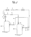
- Figure 1 is a block diagram showing a construction of an air conditioner having two compressors in accordance with the conventional art.
- an air conditioner having two compressors includes a first compressor 18A and a second compressor 18B selectively operated according to a cooling load of a room to vary compressing capacity; a condenser 1 for radiating heat of a refrigerant compressed by the first and second compressors 18A, 18B; an expansion valve 2 for expanding the refrigerant discharged from the condenser 1; and an evaporator 3 receiving the refrigerant expanded by the expansion valve 3 and generating cool air.
- the first compressor 18A is a compressor of small compressing capacity
- the second compressor 18B is a compressor of high compressing capacity
- suction pipes 9, 13 respectively connected to the first compressor 18A and the second compressor 18B are connected by hoses 5, 7 diverged from a suction hose 4 connected to the evaporator 3.
- discharge pipes 11, 14 respectively connected to the first compressor 18A and the second compressor 18B are connected by hoses 10, 16 diverged from a discharge hose 17 connected to the condenser 1.
- suction valves 6, 8 and discharge valves 12, 15 which are selectively opened/closed by hand or a control means such as a microcomputer or the like.
- the air conditioner having the two compressors controls a cooling cycle by operating the first compressor 18A or/and the second compressor 18B according to the cooling load. That is, capacities of the compressors are changed in such a manner than the air conditioner operates only the first compressor 18A when an indoor cooling load is small, operates only the second compressor 18B when the indoor cooling load is large, and operates both the first and second compressors 18A, 18B when the indoor cooling load is maximum.
- an air conditioner having four compressors has been used.
- General operations of the air conditioner having four compressors are the same as those of the air conditioner of Figure 1.
- the four compressors may be designed to have the same compressing capacity or may be designed to have different compressing capacities.
- an object of the present invention is to provide an apparatus and a method for controlling oil of an air conditioner capable of preventing damage of a compressor due to imbalance of refrigerating machine oil by uniformly dividing oil of a multi-compressor installed in the air conditioner.
- an apparatus for controlling oil of an air conditioner including: a microcomputer sequentially stopping compressors installed in an air conditioner for a preset time, and then sequentially operating the compressors when the preset time elapses; and oil pipes connected to the compressors and balancing oil in the compressors.
- an apparatus for controlling oil of an air conditioner including: a microcomputer sequentially stopping compressors installed in the air conditioner for a preset time when an operation time of the air conditioner passes a preset time and thus a mode of the air conditioner is changed to an oil control mode, and then sequentially operating the compressors when the preset time elapses; oil pipes connected to the compressors and balancing oil in the compressors; and an equalizer for maintaining internal pressure of the compressors the same in order to smoothly balance oil in the compressors.
- a method for controlling oil of an air conditioner including: sequentially stopping compressors installed in an air conditioner for a preset time when a mode of the air conditioner is changed to an oil control mode; and sequentially operating the compressors when the preset time elapses, wherein oil pipes for balancing oil in the compressors are connected to the compressors.
- a method for controlling oil of an air conditioner including: comparing an operation time of each compressor and a preset refrigerating machine oil shortage time while the compressors are operated in a cooling mode or a heating mode of the air conditioner; changing a mode of the air conditioner to an oil control mode when the operation time of each compressor passes the preset refrigerating machine oil shortage time, and then sequentially stopping the compressors for a preset stopping time; and sequentially operating the compressors when the preset stopping time elapses, and then changing the oil control mode to the cooling mode or the heating mode, wherein the compressors are connected to each other through oil pipes.
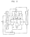
- Figure 2 is a block diagram showing a construction of an air conditioner having a multi-compressor to which an oil control apparatus is applied in accordance with a first embodiment of the present invention.
- an air conditioner having a multi-compressor in accordance with the first embodiment of the present invention includes first ⁇ fourth compressors 1 ⁇ 4; a check valve 5; outdoor heat exchangers 6, 7; first and second expansion valves 8. 9; an indoor heat exchanger 10; an accumulator 11; a divergence pipe 12; first ⁇ fourth suction pipes 13 ⁇ 16; oil pipes 17; an equalizer (not shown); and a microcomputer (not shown).
- an air conditioner having a multi-compressor e.g., four compressors
- the construction of an air conditioner having a multi-compressor is the same as the above mentioned air conditioner, except oil pipes 17 connected to the first ⁇ fourth compressors 1 ⁇ 4 and uniformly dividing the refrigerating machine oil; the equalizer; and the microcomputer.
- the first ⁇ fourth compressors are connected to one another through the oil pipes 17. That is, hereinafter, an apparatus and a method for controlling oil of a multi-compressor installed in the air conditioner, in accordance with a first embodiment of the present invention, will now be described in detail.
- An apparatus for controlling oil of a multi-compressor installed in the air conditioner includes a microcomputer sequentially stopping the first - fourth compressors 1 ⁇ 4 installed in the air conditioner for a preset time when a mode of the air conditioner is changed to an oil control mode, and then sequentially operating the first ⁇ fourth compressors 1 ⁇ 4 when the preset time elapses; oil pipes connected to each of first - fourth compressors in order that the amount of refrigerating machine oil in the first ⁇ fourth compressors maintains a normal level and is balanced; an equalizer for maintaining the same pressure in the first ⁇ fourth compressors in order to smoothly divide the refrigerating machine oil in the first ⁇ fourth compressors.
- the apparatus for controlling oil e.g., refrigerating machine oil
- a multi-compressor e.g., four compressors
- the certain amount of refrigerating machine oil is supplied to the second ⁇ fourth compressors 2 ⁇ 4 through the oil pipes 17.
- the first ⁇ fourth compressors 1 ⁇ 4 are connected by the equalizer (not shown) to thereby make inner pressures the same.
- the four compressors are sequentially stopped, and then when predetermined time elapses, the first - fourth compressors 1 ⁇ 4 are sequentially operated, so that the refrigerating machine oil in the first ⁇ fourth compressors 1 ⁇ 4 is uniformly distributed through the oil pipes 17 connected to the first - fourth compressors 1 ⁇ 4.
- the microcomputer changes a mode of the air conditioner to an oil control mode.
- the microcomputer sequentially stops the first - fourth compressors 1 ⁇ 4 installed in the air conditioner for a preset time (e.g., one minute), and then, when the preset time elapses, the microcomputer sequentially operates the first ⁇ fourth compressors 1 ⁇ 4.
- the certain amount of the refrigerating machine oil in the stopped compressor e.g., first compressor
- the compressors e.g., second ⁇ fourth compressors
- the microcomputer stops the first compressor 1 of the first ⁇ fourth compressors 1 ⁇ 4 installed in the air conditioner for one minute, and then when the one minute elapses, the microcomputer operates the first compressor 1.
- the microcomputer stops the second compressor 2 for one minute.
- the microcomputer operates the second compressor 2, and after operating the second compressor 2, the microcomputer stops the third compressor 3 for one minute.
- the microcomputer operates the third compressor 3, and after operating the third compressor 3, the microcomputer stops the fourth compressor 4 for one minute.
- the microcomputer operates the fourth compressor.
- the equalizer is a pipe for maintaining the internal pressure of the first ⁇ fourth compressors the same in order that the refrigerating machine oil in the first ⁇ fourth compressors 1 ⁇ 4 is smoothly exchanged, but it is not an essential component. That is, the refrigerating machine oil in the first - fourth compressors is properly exchanged through the oil pipes 17 even without the equalizer.
- Figure 3 is a block diagram showing a construction of an air conditioner having a multi-compressor including an oil control apparatus in accordance with a second embodiment of the present invention.
- an apparatus for controlling oil of a multi-compressor installed in an air conditioner in accordance with the second embodiment of the present invention includes a microcomputer for sequentially stopping first - fourth compressors 1 ⁇ 4 installed in the air conditioner for a preset time when a mode of the air conditioner is changed to an oil control mode, and then sequentially operating the first ⁇ fourth compressors when the preset time elapses; and oil pipes connected to the first ⁇ fourth compressors in parallel in order that the amount of refrigerating machine oil in the first - fourth compressors maintains a normal level and is balanced.
- the oil pipes 17 are connected to the first ⁇ fourth compressors in parallel, thereby uniformly dividing the refrigerating machine oil.
- the divergence pipe 12 is not used in the air conditioner in accordance with the second embodiment of the present invention, and first ⁇ fourth suction pipes 13 ⁇ 16 respectively connected to the first ⁇ fourth compressors are directly connected to the accumulator 11, so that the first ⁇ fourth suction pipe 13 ⁇ 16 can be easily welded. Since an operation of the oil control apparatus in accordance with the second embodiment of the present invention is the same as that of the oil control apparatus in accordance with the first embodiment of the present invention, descriptions thereon will be omitted.
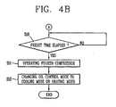
- Figures 4A-4B are an operation flow chart of an oil control method of an air conditioner in accordance with the first embodiment of the present invention. That is, Figure 4 describes an oil control method of an air conditioner when four compressors are installed in the air conditioner in accordance with the embodiment of the present invention in detail.
- an oil control method of an air conditioner in accordance with the first embodiment of the present invention includes the steps of: comparing an operation time of each of the first ⁇ fourth compressors 1 ⁇ 4 and a refrigerating machine oil shortage time that is preset according to the number of compressors, while the first - fourth compressors are operated in a cooling mode or a heating mode; changing a mode of the air conditioner to an oil control mode when the operation time of each of the first ⁇ fourth compressors 1 ⁇ 4 passes the preset refrigerating machine oil shortage time, and then stopping the first compressor 1 for a preset stopping time (e.g., for one minute); operating the first compressor 1 when the preset stopping time elapses, and then stopping the second compressor 2 for the preset stopping time; operating the second compressor 2 when the preset stopping time elapses, and then stopping the third compressor for the preset stopping time; operating the third compressor when the preset stopping time elapses, and then stopping the fourth compressor 4 for the preset stopping time; and operating the fourth compressor 4 when the prese
- the microcomputer determines whether the operation time of each of first ⁇ fourth compressors elapses the preset refrigerating machine oil shortage time while the first ⁇ fourth compressors 1 ⁇ 4 are operated in a cooling mode or a heat mode of the air conditioner.
- the preset refrigerating machine oil shortage time means a time at which a compressor (e.g., first compressor) which has insufficient refrigerating machine oil may be damaged as the refrigerating machine oil in the first - fourth compressors 1 ⁇ 4 is non-uniformly distributed when the first ⁇ fourth compressors 1 ⁇ 4 are operated for many hours.
- the refrigerating machine oil shortage time is set to be two-hour when four compressors are installed in the air conditioner (S1).
- the microcomputer changes a mode of the air conditioner to an oil control mode.
- the oil control mode is for uniformly dividing the oil in the first ⁇ fourth compressors 1 ⁇ 4 when the operation time of each of the first ⁇ fourth compressors passes the refrigerating machine oil shortage time (e.g., two-hour) (S2).
- the microcomputer stops the first compressor 1 for a preset stopping time.
- the preset stopping time is one minute (S3).
- the microcomputer When the preset stopping time elapses (S4), the microcomputer operates the first compressor 1 and then stops the second compressor 2 for the preset stopping time (S5).
- the microcomputer When the preset stopping time elapses (S6), the microcomputer operates the second compressor 2, and then stops the third compressor for the preset stopping time (S7).
- the microcomputer When the preset stopping time elapses (S8), the microcomputer operates the third compressor 3 and then stops the fourth compressor 4 for the preset stopping time (S9).
- the microcomputer operates the fourth compressor 4 (S11) and then changes the oil control mode to the cooling mode or the heating mode (S12).
- the microcomputer changes the cooling mode or the heat mode of the air conditioner to the oil control mode, so that the refrigerating machine oil in the first ⁇ fourth compressors 1 ⁇ 4 is uniformly distributed.
- FIG 5 is an operation flow chart of an oil control method of an air conditioner in accordance with the second embodiment of the present invention. That is, an oil control method of an air conditioner when three compressors are installed in the air conditioner in accordance with the embodiment of the present invention will now be described in detail.
- the oil control method of the compressors installed in the air conditioner in accordance with the second embodiment of the present invention includes: a step in which it is determined whether an operation time of each of first ⁇ third compressors 1 ⁇ 3 passes a refrigerating machine oil shortage time preset according to the number of compressors (three compressors) while the first ⁇ third compressors 1 ⁇ 3 are operated in a cooling mode or a heating mode of the air conditioner (S21); a step in which a mode of the air conditioner is changed to an oil control mode when the operation time of each of the first - third compressors passes the preset refrigerating machine oil shortage time, and then the first compressor 1 is stopped for a preset stopping time (e.g., one minute) (S22, S23); a step in which when the preset stopping time elapses (S24), the first compressor 1 is operated, and then the second compressor 2 is stopped for the preset stopping time (S25); a step in which when the preset stopping time elapses (S26), the second compressor 2
- Figure 6 is an operation flow chart of an oil control method of an air conditioner in accordance with a third embodiment of the present invention.
- the oil control method of compressors installed in the air conditioner in accordance with the third embodiment of the present invention includes: a step in which it is determined whether an operation time of each of first and second compressors 1, 2 passes a refrigerating machine oil shortage time preset according to the number of compressors (two compressors) while the first and second compressors are operated in a cooling mode or a heat mode of the air conditioner (S31); a step in which a mode of the air conditioner is changed to an oil control mode (S32) when the operation time of the first and second compressors 1, 2 passes the preset refrigerating machine oil shortage time, and then the first compressor 1 is stopped for a preset stopping time (e.g., one minute) (S33); a step in which when the preset stopping time elapses (S34), the first compressor 1 is operated, and then the second compressor 2 is stopped for the preset stopping time (S35); and a step in which when the preset stopping time elapses (S36), the second compressor is operated (S37) and
- compressors installed in the air conditioner are sequentially stopped when a mode of the air conditioner is changed to an oil control mode, and the compressors are sequentially operated when the preset time elapses, so that refrigerating machine oil in the compressors can be uniformly distributed through oil pipes connected to the compressors. That is, in the apparatus and method for controlling oil of the air conditioner in accordance with the present invention, refrigerating machine oil in the compressors is uniformly distributed, so that damage of the compressor having insufficient refrigerating machine oil due to non-uniform division of the refrigerating machine oil in the compressors when the compressors are operated for many hours can be prevented.
Landscapes
- Engineering & Computer Science (AREA)
- Physics & Mathematics (AREA)
- Mechanical Engineering (AREA)
- Thermal Sciences (AREA)
- General Engineering & Computer Science (AREA)
- Air Conditioning Control Device (AREA)
Priority Applications (2)
| Application Number | Priority Date | Filing Date | Title |
|---|---|---|---|
| DE200560021051 DE602005021051D1 (de) | 2005-02-25 | 2005-02-25 | Ölstandausgleichsanlage für mehrere Verdichter und zugehöriges Regelverfahren |
| EP20050004193 EP1703231B1 (fr) | 2005-02-25 | 2005-02-25 | Dispositif et méthode pour égaliser le niveau d'huile pour plusieurs compresseurs |
Applications Claiming Priority (1)
| Application Number | Priority Date | Filing Date | Title |
|---|---|---|---|
| EP20050004193 EP1703231B1 (fr) | 2005-02-25 | 2005-02-25 | Dispositif et méthode pour égaliser le niveau d'huile pour plusieurs compresseurs |
Publications (2)
| Publication Number | Publication Date |
|---|---|
| EP1703231A1 true EP1703231A1 (fr) | 2006-09-20 |
| EP1703231B1 EP1703231B1 (fr) | 2010-05-05 |
Family
ID=34933957
Family Applications (1)
| Application Number | Title | Priority Date | Filing Date |
|---|---|---|---|
| EP20050004193 Ceased EP1703231B1 (fr) | 2005-02-25 | 2005-02-25 | Dispositif et méthode pour égaliser le niveau d'huile pour plusieurs compresseurs |
Country Status (2)
| Country | Link |
|---|---|
| EP (1) | EP1703231B1 (fr) |
| DE (1) | DE602005021051D1 (fr) |
Cited By (14)
| Publication number | Priority date | Publication date | Assignee | Title |
|---|---|---|---|---|
| CN106247686A (zh) * | 2016-08-16 | 2016-12-21 | 广东美的暖通设备有限公司 | 空调器的回油控制方法、回油控制装置和空调器 |
| EP3287718A1 (fr) * | 2016-08-22 | 2018-02-28 | Bergstrom, Inc. | Système de climatisation de compresseurs parallèles |
| US10245916B2 (en) | 2013-11-04 | 2019-04-02 | Bergstrom, Inc. | Low profile air conditioning system |
| US10369863B2 (en) | 2016-09-30 | 2019-08-06 | Bergstrom, Inc. | Refrigerant liquid-gas separator with electronics cooling |
| US10414243B2 (en) | 2013-03-13 | 2019-09-17 | Bergstrom, Inc. | Vehicular ventilation module for use with a vehicular HVAC system |
| US10427496B2 (en) | 2015-03-09 | 2019-10-01 | Bergstrom, Inc. | System and method for remotely managing climate control systems of a fleet of vehicles |
| US10527332B2 (en) | 2016-01-13 | 2020-01-07 | Bergstrom, Inc. | Refrigeration system with superheating, sub-cooling and refrigerant charge level control |
| US10562372B2 (en) | 2016-09-02 | 2020-02-18 | Bergstrom, Inc. | Systems and methods for starting-up a vehicular air-conditioning system |
| US10589598B2 (en) | 2016-03-09 | 2020-03-17 | Bergstrom, Inc. | Integrated condenser and compressor system |
| US10675948B2 (en) | 2016-09-29 | 2020-06-09 | Bergstrom, Inc. | Systems and methods for controlling a vehicle HVAC system |
| US10724772B2 (en) | 2016-09-30 | 2020-07-28 | Bergstrom, Inc. | Refrigerant liquid-gas separator having an integrated check valve |
| US11420496B2 (en) | 2018-04-02 | 2022-08-23 | Bergstrom, Inc. | Integrated vehicular system for conditioning air and heating water |
| US11448441B2 (en) | 2017-07-27 | 2022-09-20 | Bergstrom, Inc. | Refrigerant system for cooling electronics |
| US12420616B2 (en) | 2016-08-22 | 2025-09-23 | Bergstrom, Inc. | Multi-compressor oil migration mitigation climate system |
Families Citing this family (1)
| Publication number | Priority date | Publication date | Assignee | Title |
|---|---|---|---|---|
| US10641268B2 (en) | 2015-08-11 | 2020-05-05 | Emerson Climate Technologies, Inc. | Multiple compressor configuration with oil-balancing system |
Citations (4)
| Publication number | Priority date | Publication date | Assignee | Title |
|---|---|---|---|---|
| JPH01203855A (ja) * | 1988-02-09 | 1989-08-16 | Toshiba Corp | 空気調和機 |
| EP0403239A2 (fr) * | 1989-06-14 | 1990-12-19 | Hitachi, Ltd. | Dispositif compresseur à capacité réglable |
| JPH05256532A (ja) * | 1992-03-10 | 1993-10-05 | Toshiba Ave Corp | 空気調和機 |
| JP2004116805A (ja) * | 2002-09-24 | 2004-04-15 | Fujitsu General Ltd | 多室形空気調和機の制御方法 |
-
2005
- 2005-02-25 EP EP20050004193 patent/EP1703231B1/fr not_active Ceased
- 2005-02-25 DE DE200560021051 patent/DE602005021051D1/de not_active Expired - Lifetime
Patent Citations (4)
| Publication number | Priority date | Publication date | Assignee | Title |
|---|---|---|---|---|
| JPH01203855A (ja) * | 1988-02-09 | 1989-08-16 | Toshiba Corp | 空気調和機 |
| EP0403239A2 (fr) * | 1989-06-14 | 1990-12-19 | Hitachi, Ltd. | Dispositif compresseur à capacité réglable |
| JPH05256532A (ja) * | 1992-03-10 | 1993-10-05 | Toshiba Ave Corp | 空気調和機 |
| JP2004116805A (ja) * | 2002-09-24 | 2004-04-15 | Fujitsu General Ltd | 多室形空気調和機の制御方法 |
Non-Patent Citations (3)
| Title |
|---|
| PATENT ABSTRACTS OF JAPAN vol. 013, no. 506 (M - 892) 14 November 1989 (1989-11-14) * |
| PATENT ABSTRACTS OF JAPAN vol. 018, no. 023 (M - 1541) 14 January 1994 (1994-01-14) * |
| PATENT ABSTRACTS OF JAPAN vol. 2003, no. 12 5 December 2003 (2003-12-05) * |
Cited By (27)
| Publication number | Priority date | Publication date | Assignee | Title |
|---|---|---|---|---|
| US10414243B2 (en) | 2013-03-13 | 2019-09-17 | Bergstrom, Inc. | Vehicular ventilation module for use with a vehicular HVAC system |
| US10245916B2 (en) | 2013-11-04 | 2019-04-02 | Bergstrom, Inc. | Low profile air conditioning system |
| US12304281B2 (en) | 2015-03-09 | 2025-05-20 | Bergstrom, Inc. | Systems and methods of managing a power source of a vehicle |
| US11780292B2 (en) | 2015-03-09 | 2023-10-10 | Bergstrom, Inc. | Graphical user interfaces for remotely managing climate control systems of a fleet of vehicles |
| US10967709B2 (en) | 2015-03-09 | 2021-04-06 | Bergstrom, Inc. | Graphical user interfaces for remotely managing climate control systems of a fleet of vehicles |
| US10427496B2 (en) | 2015-03-09 | 2019-10-01 | Bergstrom, Inc. | System and method for remotely managing climate control systems of a fleet of vehicles |
| US10527332B2 (en) | 2016-01-13 | 2020-01-07 | Bergstrom, Inc. | Refrigeration system with superheating, sub-cooling and refrigerant charge level control |
| US10589598B2 (en) | 2016-03-09 | 2020-03-17 | Bergstrom, Inc. | Integrated condenser and compressor system |
| CN106247686B (zh) * | 2016-08-16 | 2019-03-08 | 广东美的暖通设备有限公司 | 空调器的回油控制方法、回油控制装置和空调器 |
| CN106247686A (zh) * | 2016-08-16 | 2016-12-21 | 广东美的暖通设备有限公司 | 空调器的回油控制方法、回油控制装置和空调器 |
| US10703173B2 (en) | 2016-08-22 | 2020-07-07 | Bergstrom, Inc. | Multi-compressor climate system |
| US11479086B2 (en) | 2016-08-22 | 2022-10-25 | Bergstrom, Inc. | Multi-compressor climate system |
| US12420616B2 (en) | 2016-08-22 | 2025-09-23 | Bergstrom, Inc. | Multi-compressor oil migration mitigation climate system |
| EP3287718A1 (fr) * | 2016-08-22 | 2018-02-28 | Bergstrom, Inc. | Système de climatisation de compresseurs parallèles |
| EP4242025A3 (fr) * | 2016-08-22 | 2024-03-13 | Bergstrom, Inc. | Système de climatisation de compresseurs parallèles |
| US10081226B2 (en) | 2016-08-22 | 2018-09-25 | Bergstrom Inc. | Parallel compressors climate system |
| US10562372B2 (en) | 2016-09-02 | 2020-02-18 | Bergstrom, Inc. | Systems and methods for starting-up a vehicular air-conditioning system |
| US11712946B2 (en) | 2016-09-29 | 2023-08-01 | Bergstrom, Inc. | Systems and methods for controlling a vehicle HVAC system |
| US10675948B2 (en) | 2016-09-29 | 2020-06-09 | Bergstrom, Inc. | Systems and methods for controlling a vehicle HVAC system |
| US11241939B2 (en) | 2016-09-29 | 2022-02-08 | Bergstrom, Inc. | Systems and methods for controlling a vehicle HVAC system |
| US12240295B2 (en) | 2016-09-29 | 2025-03-04 | Bergstrom, Inc. | Systems and methods for controlling a vehicle HVAC system |
| US10369863B2 (en) | 2016-09-30 | 2019-08-06 | Bergstrom, Inc. | Refrigerant liquid-gas separator with electronics cooling |
| US10724772B2 (en) | 2016-09-30 | 2020-07-28 | Bergstrom, Inc. | Refrigerant liquid-gas separator having an integrated check valve |
| US11448441B2 (en) | 2017-07-27 | 2022-09-20 | Bergstrom, Inc. | Refrigerant system for cooling electronics |
| US12065019B2 (en) | 2017-07-27 | 2024-08-20 | Bergstrom, Inc. | Refrigerant system for cooling electronics |
| US11420496B2 (en) | 2018-04-02 | 2022-08-23 | Bergstrom, Inc. | Integrated vehicular system for conditioning air and heating water |
| US11919364B2 (en) | 2018-04-02 | 2024-03-05 | Bergstrom, Inc. | Integrated vehicular system for conditioning air and heating water |
Also Published As
| Publication number | Publication date |
|---|---|
| DE602005021051D1 (de) | 2010-06-17 |
| EP1703231B1 (fr) | 2010-05-05 |
Similar Documents
| Publication | Publication Date | Title |
|---|---|---|
| US7137265B2 (en) | Apparatus and method for controlling oil of air conditioner | |
| AU2006324596B2 (en) | Air conditioner | |
| EP1703231B1 (fr) | Dispositif et méthode pour égaliser le niveau d'huile pour plusieurs compresseurs | |
| EP2075517B1 (fr) | Système de climatisation | |
| US6951116B2 (en) | Air conditioner and method for controlling electronic expansion valve of air conditioner | |
| AU2006324593B2 (en) | Air conditioner | |
| JP6366742B2 (ja) | 空気調和装置 | |
| JP6319334B2 (ja) | 冷凍装置 | |
| JP6610274B2 (ja) | 冷凍装置および管理システム | |
| EP2218984B1 (fr) | Climatiseur et procédé de commande correspondant | |
| US6807816B2 (en) | Air conditioning system with two compressors and method for operating the same | |
| EP0410570A2 (fr) | Appareil de climatisation comprenant un contrôle de départ pour compresseurs fonctionnant parallèlement se basant sur la détection par haute pression | |
| WO2021085529A1 (fr) | Système réfrigérant | |
| KR20050099799A (ko) | 냉동 사이클 장치의 전자 팽창밸브 제어 방법 | |
| AU2006324602A1 (en) | Air conditioner | |
| JP2010139156A (ja) | 冷凍装置およびその制御方法 | |
| EP1666806A2 (fr) | Dispositif de climatisation à unités multiples et méthode de régulation pour celui-ci | |
| US7174730B2 (en) | Method for controlling air conditioner having multi-compressor | |
| JP5245576B2 (ja) | 空気調和装置の冷媒量判定方法および空気調和装置 | |
| EP1600709B1 (fr) | Conditionneur d'air à unités multiples | |
| AU2006324598B8 (en) | Air conditioner | |
| US7908878B2 (en) | Refrigerating apparatus | |
| JP5645453B2 (ja) | 空気調和装置 | |
| KR20100002771A (ko) | 멀티 공기조화 시스템의 제어방법 | |
| JP3883725B2 (ja) | 空気調和装置の運転方法及び空気調和装置 |
Legal Events
| Date | Code | Title | Description |
|---|---|---|---|
| PUAI | Public reference made under article 153(3) epc to a published international application that has entered the european phase |
Free format text: ORIGINAL CODE: 0009012 |
|
| AK | Designated contracting states |
Kind code of ref document: A1 Designated state(s): AT BE BG CH CY CZ DE DK EE ES FI FR GB GR HU IE IS IT LI LT LU MC NL PL PT RO SE SI SK TR |
|
| AX | Request for extension of the european patent |
Extension state: AL BA HR LV MK YU |
|
| 17P | Request for examination filed |
Effective date: 20070124 |
|
| AKX | Designation fees paid |
Designated state(s): DE FR GB |
|
| 17Q | First examination report despatched |
Effective date: 20080311 |
|
| GRAP | Despatch of communication of intention to grant a patent |
Free format text: ORIGINAL CODE: EPIDOSNIGR1 |
|
| RAP1 | Party data changed (applicant data changed or rights of an application transferred) |
Owner name: LG ELECTRONICS, INC. |
|
| GRAS | Grant fee paid |
Free format text: ORIGINAL CODE: EPIDOSNIGR3 |
|
| GRAA | (expected) grant |
Free format text: ORIGINAL CODE: 0009210 |
|
| AK | Designated contracting states |
Kind code of ref document: B1 Designated state(s): DE FR GB |
|
| REG | Reference to a national code |
Ref country code: GB Ref legal event code: FG4D |
|
| REF | Corresponds to: |
Ref document number: 602005021051 Country of ref document: DE Date of ref document: 20100617 Kind code of ref document: P |
|
| PLBE | No opposition filed within time limit |
Free format text: ORIGINAL CODE: 0009261 |
|
| STAA | Information on the status of an ep patent application or granted ep patent |
Free format text: STATUS: NO OPPOSITION FILED WITHIN TIME LIMIT |
|
| 26N | No opposition filed |
Effective date: 20110208 |
|
| REG | Reference to a national code |
Ref country code: DE Ref legal event code: R097 Ref document number: 602005021051 Country of ref document: DE Effective date: 20110207 |
|
| REG | Reference to a national code |
Ref country code: FR Ref legal event code: PLFP Year of fee payment: 12 |
|
| REG | Reference to a national code |
Ref country code: FR Ref legal event code: PLFP Year of fee payment: 13 |
|
| PGFP | Annual fee paid to national office [announced via postgrant information from national office to epo] |
Ref country code: DE Payment date: 20170105 Year of fee payment: 13 |
|
| PGFP | Annual fee paid to national office [announced via postgrant information from national office to epo] |
Ref country code: GB Payment date: 20170105 Year of fee payment: 13 |
|
| REG | Reference to a national code |
Ref country code: FR Ref legal event code: PLFP Year of fee payment: 14 |
|
| REG | Reference to a national code |
Ref country code: DE Ref legal event code: R119 Ref document number: 602005021051 Country of ref document: DE |
|
| GBPC | Gb: european patent ceased through non-payment of renewal fee |
Effective date: 20180225 |
|
| PG25 | Lapsed in a contracting state [announced via postgrant information from national office to epo] |
Ref country code: DE Free format text: LAPSE BECAUSE OF NON-PAYMENT OF DUE FEES Effective date: 20180901 |
|
| PG25 | Lapsed in a contracting state [announced via postgrant information from national office to epo] |
Ref country code: GB Free format text: LAPSE BECAUSE OF NON-PAYMENT OF DUE FEES Effective date: 20180225 |
|
| PGFP | Annual fee paid to national office [announced via postgrant information from national office to epo] |
Ref country code: FR Payment date: 20200108 Year of fee payment: 16 |
|
| PG25 | Lapsed in a contracting state [announced via postgrant information from national office to epo] |
Ref country code: FR Free format text: LAPSE BECAUSE OF NON-PAYMENT OF DUE FEES Effective date: 20210228 |