EP1703246A1 - Mehrläufige Handfeuerwaffe - Google Patents
Mehrläufige Handfeuerwaffe Download PDFInfo
- Publication number
- EP1703246A1 EP1703246A1 EP06000462A EP06000462A EP1703246A1 EP 1703246 A1 EP1703246 A1 EP 1703246A1 EP 06000462 A EP06000462 A EP 06000462A EP 06000462 A EP06000462 A EP 06000462A EP 1703246 A1 EP1703246 A1 EP 1703246A1
- Authority
- EP
- European Patent Office
- Prior art keywords
- running rail
- barreled
- longitudinal slot
- wedge
- adjusting
- Prior art date
- Legal status (The legal status is an assumption and is not a legal conclusion. Google has not performed a legal analysis and makes no representation as to the accuracy of the status listed.)
- Granted
Links
Images


Classifications
-
- F—MECHANICAL ENGINEERING; LIGHTING; HEATING; WEAPONS; BLASTING
- F41—WEAPONS
- F41A—FUNCTIONAL FEATURES OR DETAILS COMMON TO BOTH SMALLARMS AND ORDNANCE, e.g. CANNONS; MOUNTINGS FOR SMALLARMS OR ORDNANCE
- F41A21/00—Barrels; Gun tubes; Muzzle attachments; Barrel mounting means
- F41A21/06—Plural barrels
- F41A21/08—Barrel junctions
Definitions
- the invention relates to a multi-barreled handgun, in particular a double-barreled tipping weapon, according to the preamble of claim 1.
- Known barrel bundles is used to avoid an exchange of spacers between the two runs in the area of the muzzle firmly soldered holding piece and a contrast movable spacer with an adjustable fitting.
- Trained as a grain saddle spacer is located with a concave side surface on one of the runs and contains a side view, in which the form-fitting fitting on the other barrel fitting is used.
- the fitting is designed as an adjusting wedge, so that the running ends are more or less pressed apart by adjusting the fitting.
- the one facing the barrel Surface of the fitting is concavely arched, which is made possible by appropriate choice of the cylinder axis of the curvature either only a lateral adjustment of the running or a simultaneous adjustment in lateral and vertical direction. An independent height and lateral adjustment of the running is not provided in this known running adjustment.
- the object of the invention is to provide a multi-barreled handgun, in which a simple and independent side and height adjustment of the runs is possible.
- the running rail is divided by the longitudinal slot at the front end into separate sections.
- the separated by the longitudinal slot sections can be spread apart by relatively simple adjustment and offset in height against each other, whereby a separate side and height adjustment of the runs is possible.
- the slotted at the front end track is designed such that the Laufseelenachsen the attached to her runs cross without employment by the adjustment already at a short distance to the muzzle.
- the running rail can be pushed apart at the front end in a first direction and thus the distance of the intersection of the Laufseelenachsen be increased from the muzzle.
- at least one of the sections of the running rail separated by the longitudinal slot can be displaced relative to the other section in a second adjustment direction perpendicular to the first adjustment direction, whereby the height position of the runs can be changed or adjusted relative to each other.
- the first adjusting device includes a displaceable by means of a set screw adjusting wedge, the between the two separated by the longitudinal slot sections of the track rail is arranged.
- the adjusting wedge is preferably displaceably guided in a wedge-shaped recess open to the longitudinal slot in one of the sections of the running rail which are separated by the longitudinal slot.
- the adjusting wedge is assigned a counterpart arranged in the other section of the running rail. Adjustment wedge and counterpart are preferably made of a wear-resistant material and can be easily replaced if necessary.
- the second adjusting device for the height adjustment comprises at least one adjusting screw, which is arranged in a direction perpendicular to the longitudinal axis of the running rail through one of the two sections of the running rail threaded hole and reaches with its inner end face to rest on the underside of a mounted on the other section grain saddle.
- the running part 1 shows a running part 1 of a double-barreled tipping weapon with two juxtaposed barrels 2 and 3 in a sectional side view and a front view shown.
- This running part 1 is tiltably arranged in a manner known per se on a closure housing (not shown here) or a base of the tilting weapon and is held by a removable forearm.
- the running part 1 comprises a running in the weapon longitudinal direction rail 4 and a so-called hook piece 5, where the two runs 2 and 3 are attached. In the hook piece 5, the rear ends of the two runs 2 and 3 are soldered or secured in any other suitable manner.
- the runs 2 and 3 are also firmly connected to the entire length of the hook piece 5 to the front end of the runs 2 and 3 extending track 4.
- the two runs 2 and 3 for example, at the two concave executed, adapted to the curvature of the runs 2 and 3 side surfaces 6 and 7 of the running rail 4 are soldered.
- a sighting rail 8 On the rear part of the running rail 4 and the hook piece 3 is a sighting rail 8 and on the front end of the running rail 2, a grain saddle 9 with a grain 10 releasably secured by screws.
- the running rail 4 has in its front area, i. at its front end seen in the weft direction, a longitudinal slot 11 made by wire erosion or another suitable method.
- a longitudinal slot 11 made by wire erosion or another suitable method.
- the front region of the running rail 4 seen in the weft direction is divided into two separate sections 4a and 4b.
- a first adjusting device 12 for the lateral adjustment of the two runs 2 and 3 is provided between the two sections 4a and 4b.
- the adjustment 12 the lateral distance between the two sections 4a and 4b and thus the lateral distance of the two front running ends can be changed.
- the adjusting device 12 for the lateral adjustment of the two runs 2 and 3 in the embodiment shown as a wedge adjustment with a displaceable by a screw 13 adjusting wedge 14, in an open to the longitudinal slot 11 wedge-shaped recess 15 in the section 4a of the running rail 4 is arranged.
- the adjusting wedge 14 has an oblique wedge surface 16, which comes to bear against a corresponding oblique mating surface 17 in the wedge-shaped recess 15.
- the adjusting wedge 14 further includes a longitudinal slot 11 facing straight contact surface 18 which comes to rest against a support surface 19 of a arranged in the section 4b counterpart 20.
- the counterpart 20 is in one of its shape adapted recess 21 in section 4b of the track rail 4 is inserted.
- Both the adjusting wedge 14 and the counterpart 20 are easily replaceable and expediently consist of hardened steel, hard metal or another wear-resistant material.
- the recess 15 and the recess 21 in the running rail 4 are also open at the top, so that the adjusting wedge 14 and the counterpart 20 can be easily exchanged with degraded grain saddle 9.
- the adjusting screw 13 is arranged in an accessible from the front end side of the portion 4 a threaded bore 22 which extends in the longitudinal direction of the running rail 4 and opens into the recess 15.
- a semicircular bulge 24 is provided on the inner side surface of section 4b of the running rail 4 facing the longitudinal slot 11, which recess engages in a corresponding depression 25 on the opposite side surface of the section 4a.
- the bulge 24 serves to receive a transverse to the running rail 4 threaded bore 26 which lies on the longitudinal axis 23.
- About the threaded bore 26 of the grain saddle 9 by means of a screw 27 on the running rail 4 can be fastened.
- holes 28 are still mounted for dowel pins 29 in the section 4b of the running rail 4.
- a threaded bore 31 arranged perpendicularly to its longitudinal axis 23 extends through the section 4a of the longitudinal rail 4 with a set screw 32 arranged therein.
- the adjusting screw 32 rests with its inner end face 33 on the underside 34 of FIG shown screw 27 and the pins 29 with the section 4b fixedly connected to the saddle 9, so that the section 4a of the track 2 by adjusting the screw 32 relative to the section 4b perpendicular to the longitudinal axis 23 adjusted and thus the altitude of the barrel 2 relative to the barrel. 3 can be changed.
- a lock screw 35 shown in Figures 2 and 5 from the bottom of the track by a corresponding Senkloch 36 of the track 2 engages in a threaded bore 37 on the underside of the caliper 9, the selected by the screw 32 setting can be secured.
- the invention is not limited to the embodiment described above and illustrated in the drawings.
- the invention is e.g. also applicable to small arms, in which the barrels are not arranged side by side, but one above the other.
Landscapes
- Engineering & Computer Science (AREA)
- General Engineering & Computer Science (AREA)
- Toys (AREA)
- Mutual Connection Of Rods And Tubes (AREA)
- Machines For Laying And Maintaining Railways (AREA)
- Beans For Foods Or Fodder (AREA)
- Coloring Foods And Improving Nutritive Qualities (AREA)
- Medicines Containing Plant Substances (AREA)
- Connection Of Plates (AREA)
Abstract
Description
- Die Erfindung betrifft eine mehrläufige Handfeuerwaffe, insbesondere eine doppelläufige Kipplaufwaffe, nach dem Oberbegriff des Anspruchs 1.
- Bei mehrläufigen Handfeuerwaffen sind die Läufe vielfach über Schienen oder Reifen zu einem Laufbündel miteinander verlötet. Um bei derartigen Waffen auch ohne aufwändige Lötarbeiten eine nachträgliche Justierung der Treffpunktlagen der Läufe zu ermöglichen, sind bereits eine Vielzahl von Einstelleinrichtungen vorgeschlagen worden, mit denen die gegenseitige Lage der beiden Laufseelenachsen im Bereich der Laufmündungen veränderbar ist.
- Aus der
DE 92 05 219 U1 ist ein Laufbündel einer mehrläufigen Handfeuerwaffe bekannt, bei dem im Mündungsbereich der über Schienen oder Reifen miteinander verlöteten Läufe ein die Lage der Läufe zueinander regulierendes Distanzstück formschlüssig zwischen die Läufe eingesetzt ist. Das Distanzstück ist in Laufrichtung zweigeteilt und enthält ein zwischen die Läufe fest eingelötetes Halteteil und ein auswechselbares Einstellteil, das an dem Halteteil lösbar angeordnet ist. Durch Nachstellen, Nacharbeiten oder Austausch des auswechselbaren Einstellteils kann so die gegenseitige Lauflage eingestellt bzw. nachreguliert werden. Bei einer derartigen Einstelleinrichtung ist jedoch die Nacharbeitung des Einstellteils relativ aufwändig und es müssen eine Reihe von auswechselbaren Einstellteilen zur Verfügung gestellt werden. - Bei einem aus der
DE 296 06 652 U1 bekannten Laufbündel ist zur Vermeidung eines Austausches von Distanzstücken zwischen die beiden Läufe im Bereich der Laufmündung ein fest eingelötetes Haltestück und ein demgegenüber bewegliches Distanzstück mit einem verstellbaren Formstück eingesetzt. Das als Kornsattel ausgebildete Distanzstück liegt mit einer konkaven Seitenfläche an einem der Läufe an und enthält eine seitliche Aufnahme, in die das an dem anderen Lauf formschlüssig anliegende Formstück eingesetzt ist. Das Formstück ist als Verstellkeil ausgeführt, so dass die Laufenden durch Verstellen des Formstücks mehr oder weniger auseinandergedrückt werden. Die dem Lauf zugewandte Fläche des Formstücks ist konkav gewölbt, wobei durch entsprechende Wahl der Zylinderachse der Wölbung entweder nur eine Seitenverstellung der Laufenden oder eine gleichzeitige Verstellung in Seiten- und Höhenrichtung ermöglicht wird. Eine voneinander unabhängige Höhen- und Seitenverstellung der Laufenden ist jedoch bei dieser bekannten Laufverstellung nicht vorgesehen. - Aufgabe der Erfindung ist es, eine mehrläufige Handfeuerwaffe zu schaffen, bei der eine einfache und voneinander unabhängige Seiten- und Höhenverstellung der Läufe ermöglicht wird.
- Diese Aufgabe wird durch eine mehrläufige Handfeuerwaffe mit den Merkmalen des Anspruchs 1 gelöst. Zweckmäßige Weiterbildungen und vorteilhafte Ausführungsformen der Erfindung sind Gegenstand der Unteransprüche.
- Bei der erfindungsgemäßen Handfeuerwaffe ist die Laufschiene durch den Längsschlitz am vorderen Ende in voneinander getrennte Abschnitte geteilt. Die durch den Längsschlitz getrennten Abschnitte können durch relativ einfache Verstelleinrichtungen auseinandergespreizt und in der Höhe gegeneinander versetzt werden, wodurch eine getrennte Seiten- und Höhenverstellung der Läufe ermöglicht wird.
- Die am vorderen Ende geschlitzte Laufschiene ist derart ausgeführt, dass sich die Laufseelenachsen der an ihr befestigten Läufe ohne Anstellung durch die Verstelleinrichtungen bereits in einem kurzen Abstand nach der Laufmündung kreuzen. Durch die erste Verstelleinrichtung kann die Laufschiene am vorderen Ende in einer ersten Richtung auseinandergedrückt und damit der Abstand des Kreuzungspunktes der Laufseelenachsen von der Laufmündung vergrößert werden. Mit Hilfe der zweiten Verstelleinrichtung kann mindestens einer der durch den Längsschlitz getrennten Abschnitte der Laufschiene gegenüber dem anderen Abschnitt in einer zur ersten Verstellrichtung senkrechten zweiten Verstellrichtung verschoben werden, wodurch die Höhenlage der Läufe zueinander verändert bzw. eingestellt werden kann.
- In einer besonders zweckmäßigen Ausführung der Erfindung enthält die erste Verstelleinrichtung einen mittels einer Stellschraube verschiebbaren Verstellkeil, der zwischen den beiden durch den Längsschlitz getrennten Abschnitten der Laufschiene angeordnet ist.
- Der Verstellkeil ist vorzugsweise in einer zum Längsschlitz offenen keilförmigen Ausnehmung in einem der durch den Längsschlitz getrennten Abschnitte der Laufschiene verschiebbar geführt. In einer weiteren zweckmäßigen Ausführung ist dem Verstellkeil ein im anderen Abschnitt der Laufschiene angeordnetes Gegenstück zugeordnet. Verstellkeil und Gegenstück bestehen bevorzugt aus einem verschleißfesten Material und können bei Bedarf einfach ausgetauscht werden.
- Die zweite Verstelleinrichtung für die Höhenverstellung umfasst mindestens eine Stellschraube, die in einer senkrecht zur Längsachse der Laufschiene durch einen der beiden Abschnitte der Laufschiene verlaufenden Gewindebohrung angeordnet ist und mit ihrer inneren Stirnfläche zur Anlage an der Unterseite eines auf dem anderen Abschnitt befestigten Kornsattels gelangt.
- Weitere Besonderheiten und Vorzüge der Erfindung ergeben sich aus der folgenden Beschreibung eines bevorzugten Ausführungsbeispiels anhand der Zeichnung. Es zeigen:
- Figur 1:
- den Laufteil einer doppelläufigen Kipplaufwaffe in einer geschnittenen Seitenansicht und einer Vorderansicht;
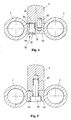
- Figur 2:
- den vorderen Bereich des im Figur 1 gezeigten Laufteils mit Laufschiene; Läufen und einem Kornsattel in einem Längsschnitt und einer Vorderansicht;
- Figur 3:
- den vorderen Teil der Laufschiene in einer Draufsicht;
- Figur 4:
- eine vergrößerte Schnittansicht entlang der Linie A-A von Figur 3 und
- Figur 5:
- eine vergrößerte Schnittansicht entlang der Linie A-A von Figur 3.
- In Figur 1 ist ein Laufteil 1 einer doppelläufigen Kipplaufwaffe mit zwei nebeneinander angeordneten Läufen 2 und 3 in einer geschnittenen Seitenansicht und einer Vorderansicht gezeigt. Dieser Laufteil 1 ist in an sich bekannter Weise kippbar an einem hier nicht gezeigten Verschlussgehäuse bzw. einer Basküle der Kipplaufwaffe angeordnet und wird durch einen abnehmbaren Vorderschaft gehalten. Der Laufteil 1 umfasst eine in Waffenlängsrichtung verlaufende Laufschiene 4 und ein so genanntes Hakenstück 5, an denen die beiden Läufe 2 und 3 befestigt sind. In dem Hakenstück 5 sind die hinteren Enden der beiden Läufe 2 und 3 eingelötet oder auf andere geeignete Weise befestigt. Die Läufe 2 und 3 sind ferner auf der gesamten Länge der von dem Hakenstück 5 bis zum vorderen Ende der Läufe 2 und 3 verlaufenden Laufschiene 4 fest mit dieser verbunden. Bei der gezeigten Ausführung sind die beiden Läufe 2 und 3 z.B. an den beiden konkav ausgeführten, an die Krümmung der Läufe 2 und 3 angepassten Seitenflächen 6 und 7 der Laufschiene 4 angelötet. Auf dem hinteren Teil der Laufschiene 4 und dem Hakenstücks 3 ist eine Visierschiene 8 und auf dem vorderen Ende der Laufschiene 2 ein Kornsattel 9 mit einem Korn 10 über Schrauben lösbar befestigt.
- Wie besonders aus den Figuren 2 und 3 ersichtlich, weist die Laufschiene 4 in ihrem vorderen Bereich, d.h. an ihrem in Schussrichtung gesehen vordere Ende, einen durch Drahterosion oder ein anderes geeignetes Verfahren hergestellten Längsschlitz 11 auf. Durch den zum vorderen Ende der Laufschiene 4 hin offenen Längsschlitz 11 wird der in Schussrichtung gesehen vordere Bereich der Laufschiene 4 in zwei voneinander getrennte Abschnitte 4a und 4b geteilt. Zwischen den beiden Abschnitten 4a und 4b ist eine erste Verstelleinrichtung 12 für die Seitenverstellung der beiden Läufe 2 und 3 vorgesehen. Durch die Verstelleinrichtung 12 kann der seitliche Abstand zwischen den beiden Abschnitten 4a und 4b und damit der seitliche Abstand der beiden vorderen Laufenden verändert werden.
- Wie aus den Figuren 2 und 3 hervorgeht, ist die Verstelleinrichtung 12 für die Seitenverstellung der beiden Läufe 2 und 3 beim gezeigten Ausführungsbeispiel als Keilverstellung mit einem durch eine Stellschraube 13 verschiebbaren Verstellkeil 14 ausgeführt, der in einer zum Längsschlitz 11 offenen keilförmigen Aussparung 15 im Abschnitt 4a der Laufschiene 4 angeordnet ist. Wie aus der Draufsicht der Laufschiene 4 in Figur 4 hervorgeht, weist der Verstellkeil 14 eine schräge Keilfläche 16 auf, die zur Anlage an einer dazu korrespondierenden schrägen Gegenfläche 17 im Inneren der keilförmigen Aussparung 15 gelangt. Der Verstellkeil 14 enthält ferner eine zum Längsschlitz 11 weisende gerade Anlagefläche 18, die zur Anlage an einer Auflagefläche 19 eines in dem Abschnitt 4b angeordneten Gegenstücks 20 kommt. Das Gegenstück 20 ist in eine an dessen Form angepasste Ausnehmung 21 im Abschnitt 4b der Laufschiene 4 eingesetzt. Sowohl der Verstellkeil 14 als auch das Gegenstück 20 sind einfach auswechselbar und bestehen zweckmäßigerweise aus gehärtetem Stahl, Hartmetall oder aus einem anderen verschleißfesten Material. Die Aussparung 15 und die Ausnehmung 21 in der Laufschiene 4 sind auch nach oben offen, so dass der Verstellkeil 14 und das Gegenstück 20 bei abgebautem Kornsattel 9 einfach ausgetauscht werden können. Die Stellschraube 13 ist in einer von der vorderen Stirnseite des Abschnitts 4a zugänglichen Gewindebohrung 22 angeordnet, die in Längsrichtung der Laufschiene 4 verläuft und in die Aussparung 15 mündet. Durch Verstellung der Stellschraube 13 wird der Verstellkeil 14 infolge der Keilwirkung auch quer zur Längsachse 23 der Laufschiene 4 verschoben, wodurch die beiden vorderen Abschnitte 4a und 4b der Laufschiene 4 und damit die beiden vorderen Laufenden auseinandergespreizt bzw. wieder aufeinander zu bewegt werden können.
- Wie in Figur 3 erkennbar, ist an der zum Längsschlitz 11 weisenden inneren Seitenfläche des Abschnitts 4b der Laufschiene 4 eine halbrunde Ausbuchtung 24 vorgesehen, die in eine entsprechende Vertiefung 25 an der gegenüberliegenden Seitenfläche des Abschnitts 4a eingreift. Die Ausbuchtung 24 dient zur Aufnahme einer quer zur Laufschiene 4 verlaufenden Gewindebohrung 26, die auf der Längsachse 23 liegt. Über die Gewindebohrung 26 ist der Kornsattel 9 mit Hilfe einer Schraube 27 auf der Laufschiene 4 befestigbar. Zur lagegenauen Anordnung des Komsattels 9 auf der Laufschiene 4 sind in dem Abschnitt 4b der Laufschiene 4 noch Bohrungen 28 für Passstifte 29 angebracht.
- Neben der Seitenverstellung der beiden Läufe ist über den Längsschlitz 11 mit Hilfe einer in Figur 4 erkennbaren zweiten Verstelleinrichtung 30 auch eine Einstellung der Höhenlage der beiden Läufe 2 und 3 zueinander möglich. Wie in Figur 4 ersichtlich, verläuft hierzu durch den Abschnitt 4a der Längsschiene 4 eine senkrecht zu deren Längsachse 23 angeordnete Gewindebohrung 31 mit einer darin angeordneten Stellschraube 32. Die Stellschraube 32 liegt mit ihrer inneren Stirnfläche 33 an der Unterseite 34 des über die in Figur 2 gezeigte Schraube 27 und die Stifte 29 mit dem Abschnitt 4b fest verbundenen Komsattels 9 an, so dass der Abschnitt 4a der Laufschiene 2 durch Verstellung der Stellschraube 32 gegenüber dem Abschnitt 4b senkrecht zur Längsachse 23 verstellt und damit die Höhenlage des Laufs 2 gegenüber dem Lauf 3 verändert werden kann. Über eine in den Figuren 2 und 5 dargestellte Konterschraube 35, die von der Unterseite der Laufschiene durch ein entsprechendes Senkloch 36 der Laufschiene 2 in eine Gewindebohrung 37 an der Unterseite des Komsattels 9 eingreift, kann die durch die Stellschraube 32 gewählte Einstellung gesichert werden.
- Die Erfindung ist nicht auf das vorstehend beschriebene und in den Zeichnungen dargestellte Ausführungsbeispiel beschränkt. So ist die Erfindung z.B. auch bei Handfeuerwaffen anwendbar, bei denen die Läufe nicht nebeneinander, sondern übereinander angeordnet sind.
Claims (11)
- Mehrläufige Handfeuerwaffe, insbesondere doppelläufige Kipplaufwaffe, mit mehreren Läufen (2, 3), die an einer gemeinsamen Laufschiene (4) befestigt sind,
dadurch gekennzeichnet, dass die Laufschiene (4) an ihrem in Schussrichtung gesehen vorderen Ende durch einen Längsschlitz (11) in voneinander getrennte Abschnitte (4a, 4b) geteilt ist und dass an der Laufschiene (4) im Bereich des Längsschlitzes (11) eine erste Verstelleinrichtung (12) zur Seitenverstellung der Läufe (4, 5) und eine zweite Verstelleinrichtung (30) zur Höhenverstellung mindestens eines Laufes (2) gegenüber dem anderen Lauf (3) angeordnet ist. - Mehrläufige Handfeuerwaffe nach Anspruch 1, dadurch gekennzeichnet, dass die erste Verstelleinrichtung (12) einen mittels einer Stellschraube (13) verschiebbaren Verstellkeil (14) zwischen den durch den Längsschlitz (11) getrennten Abschnitten (4a, 4b) der Laufschiene (4) enthält.
- Mehrläufige Handfeuerwaffe nach Anspruch 1 und 2, dadurch gekennzeichnet, dass der Verstellkeil (14) in einer zum Längsschlitz (11) offenen keilförmigen Aussparung (15) in einem der durch den Längsschlitz (11) getrennten Abschnitte (4a, 4b) der Laufschiene (4) verschiebbar geführt ist.
- Mehrläufige Handfeuerwaffe nach Anspruch 3, dadurch gekennzeichnet, dass der Verstellkeil (14) eine schräge Keilfläche (16) zur Anlage an einer dazu korrespondierenden schrägen Gegenfläche (17) in Inneren der keilförmigen Aussparung (15) aufweist.
- Mehrläufige Handfeuerwaffe nach Anspruch 3 oder 4, dadurch gekennzeichnet, dass dem in der Aussparung (15) des einen Abschnitts (4a) geführten Verstellkeil (14) ein in einer Ausnehmung (21) des anderen Abschnitts (4b) angeordnetes Gegenstück (20) zugeordnet ist.
- Mehrläufige Handfeuerwaffe nach Anspruch 5, dadurch gekennzeichnet, dass der Verstellkeil (14) eine zum Längsschlitz (11) weisende gerade Anlagefläche (18) zur Anlage an einer geraden Auflagefläche (19) des Gegenstücks (20) aufweist.
- Mehrläufige Handfeuerwaffe nach einem der Ansprüche 5 oder 6, dadurch gekennzeichnet, dass die Aussparung (15) und die Ausnehmung (21) zur Oberseite der Laufschiene (4) offen und durch einen auf der Laufschiene (4) lösbar befestigten Kornsattel (9) abgedeckt sind.
- Mehrläufige Handfeuerwaffe nach einem der Ansprüche 5 bis 7, dadurch gekennzeichnet, dass der Verstellkeil (14) und das Gegenstück (20) aus gehärtetem Stahl, Hartmetall oder einem anderen verschleißfesten Material bestehen.
- Mehrläufige Handfeuerwaffe nach einem der Ansprüche 1 bis 8, dadurch gekennzeichnet, dass die zweite Verstelleinrichtung (30) mindestens eine Stellschraube (32) umfasst, die in einer senkrecht zur Längsachse (23) der Laufschiene (4) durch einen der beiden Abschnitte (4a) der Laufschiene (4) verlaufenden Gewindebohrung (31) angeordnet ist und mit ihrer inneren Stirnfläche (33) zur Anlage an der Unterseite (34) eines auf dem anderen Abschnitt (4b) befestigten Komsattels (9) gelangt.
- Mehrläufige Handfeuerwaffe nach Anspruch 9, dadurch gekennzeichnet, dass an der Unterseite des Kornsattels (9) eine Gewindebohrung (37) für eine in einem Senkloch (36) der Laufschiene (36) angeordnete Konterschraube (35) vorgesehen ist.
- Mehrläufige Handfeuerwaffe nach einem der Ansprüche 1 bis 10, dadurch gekennzeichnet, dass der Längsschlitz (11) in der Laufschiene (4) durch Drahterosion hergestellt ist.
Applications Claiming Priority (1)
| Application Number | Priority Date | Filing Date | Title |
|---|---|---|---|
| DE102005012513A DE102005012513B4 (de) | 2005-03-16 | 2005-03-16 | Mehrläufige Handfeuerwaffe |
Publications (2)
| Publication Number | Publication Date |
|---|---|
| EP1703246A1 true EP1703246A1 (de) | 2006-09-20 |
| EP1703246B1 EP1703246B1 (de) | 2009-09-16 |
Family
ID=36571486
Family Applications (1)
| Application Number | Title | Priority Date | Filing Date |
|---|---|---|---|
| EP06000462A Expired - Lifetime EP1703246B1 (de) | 2005-03-16 | 2006-01-11 | Mehrläufige Handfeuerwaffe |
Country Status (4)
| Country | Link |
|---|---|
| EP (1) | EP1703246B1 (de) |
| AT (1) | ATE443241T1 (de) |
| DE (2) | DE102005012513B4 (de) |
| DK (1) | DK1703246T3 (de) |
Cited By (1)
| Publication number | Priority date | Publication date | Assignee | Title |
|---|---|---|---|---|
| EP2916095A1 (de) * | 2014-03-06 | 2015-09-09 | L&O Hunting Group GmbH | Laufhalterung und Laufbündel mit mindestens einer derartigen Laufhalterung |
Citations (4)
| Publication number | Priority date | Publication date | Assignee | Title |
|---|---|---|---|---|
| US4270296A (en) * | 1977-12-29 | 1981-06-02 | Paul Chapuis | Point of impact adjustment means for firearm barrels |
| DE3415852A1 (de) * | 1983-04-28 | 1984-10-31 | Johann Ing. Kufstein Kepplinger | Einrichtung zur festlegung der beiden vorderen laufenden einer doppellaeufigen waffe |
| DE9205219U1 (de) | 1992-04-15 | 1992-06-11 | H. Krieghoff GmbH, 7900 Ulm | Laufbündel für ein Gewehr |
| DE19538006C1 (de) | 1995-10-12 | 1997-04-17 | Jun Peter Fortner | Justiereinrichtung für eine zumindest zweiläufige Waffe |
Family Cites Families (1)
| Publication number | Priority date | Publication date | Assignee | Title |
|---|---|---|---|---|
| DE29606652U1 (de) * | 1996-04-12 | 1996-08-01 | H. Krieghoff GmbH, 89079 Ulm | Laufbündel für ein Gewehr |
-
2005
- 2005-03-16 DE DE102005012513A patent/DE102005012513B4/de not_active Expired - Lifetime
-
2006
- 2006-01-11 AT AT06000462T patent/ATE443241T1/de active
- 2006-01-11 DE DE502006004830T patent/DE502006004830D1/de not_active Expired - Lifetime
- 2006-01-11 DK DK06000462T patent/DK1703246T3/da active
- 2006-01-11 EP EP06000462A patent/EP1703246B1/de not_active Expired - Lifetime
Patent Citations (4)
| Publication number | Priority date | Publication date | Assignee | Title |
|---|---|---|---|---|
| US4270296A (en) * | 1977-12-29 | 1981-06-02 | Paul Chapuis | Point of impact adjustment means for firearm barrels |
| DE3415852A1 (de) * | 1983-04-28 | 1984-10-31 | Johann Ing. Kufstein Kepplinger | Einrichtung zur festlegung der beiden vorderen laufenden einer doppellaeufigen waffe |
| DE9205219U1 (de) | 1992-04-15 | 1992-06-11 | H. Krieghoff GmbH, 7900 Ulm | Laufbündel für ein Gewehr |
| DE19538006C1 (de) | 1995-10-12 | 1997-04-17 | Jun Peter Fortner | Justiereinrichtung für eine zumindest zweiläufige Waffe |
Cited By (1)
| Publication number | Priority date | Publication date | Assignee | Title |
|---|---|---|---|---|
| EP2916095A1 (de) * | 2014-03-06 | 2015-09-09 | L&O Hunting Group GmbH | Laufhalterung und Laufbündel mit mindestens einer derartigen Laufhalterung |
Also Published As
| Publication number | Publication date |
|---|---|
| EP1703246B1 (de) | 2009-09-16 |
| DE502006004830D1 (de) | 2009-10-29 |
| DE102005012513B4 (de) | 2006-11-30 |
| ATE443241T1 (de) | 2009-10-15 |
| DK1703246T3 (da) | 2009-11-30 |
| DE102005012513A1 (de) | 2006-09-21 |
Similar Documents
| Publication | Publication Date | Title |
|---|---|---|
| EP1688696B1 (de) | Verstellbare Schaftkappe für eine Handfeuerwaffe | |
| EP0216015B1 (de) | Gewehr mit einer Laufhalterung für Wechselläufe | |
| DE19918635C1 (de) | Montageeinrichtung | |
| EP1975541B1 (de) | Schaft eines Repetiergewehrs und Systemkasten eines Repetiergewehrs für einen derartigen Schaft | |
| DE102018132756B4 (de) | Umrüstsatz für eine Kurzwaffe | |
| DE3326521A1 (de) | Wechsellauf fuer colt-selbstladepistolen | |
| EP2660553A2 (de) | Montagevorrichtung zur lösbaren Befestigung einer Zieleinrichtung an einer Handfeuerwaffe | |
| EP1500897B1 (de) | Verschluss für eine Repetierwaffe | |
| DE3129182C2 (de) | Schaftbacke, insbesondere für Sportgewehre | |
| EP2083237B1 (de) | Laufbündel einer Handfeuerwaffe | |
| EP3973244B1 (de) | Obergehäuse für eine feuerwaffe | |
| EP1703246B1 (de) | Mehrläufige Handfeuerwaffe | |
| EP1559984B1 (de) | Handfeuerwaffe | |
| EP0115034A1 (de) | Gewehr mit auswechselbarem Lauf | |
| EP3809093A1 (de) | Montagevorrichtung für ein zielfernrohr bei einer jagd- oder sportwaffe mit mindestens einem federnden stehbolzen | |
| EP1830154B1 (de) | Verstellbare Visiereinrichtung für eine Handfeuerwaffe | |
| DE202005004388U1 (de) | Mehrläufige Handfeuerwaffe | |
| DE102016102403B4 (de) | Kipplaufwaffe | |
| EP0548515B1 (de) | Lagereinrichtung für den Stössel einer Sägemaschine | |
| EP3689545A1 (de) | Spannbacke zum spannen eines werkstücks | |
| DE2512476A1 (de) | Luftgewehr | |
| DE202005007224U1 (de) | Visiereinrichtung für eine Handfeuerwaffe | |
| DE20313020U1 (de) | Vorrichtung zur Befestigung einer Zieleinrichtung an einer Waffe | |
| EP4610589A1 (de) | Vorrichtung zur befestigung einer zieleinrichtung an einer schusswaffe | |
| DE20012672U1 (de) | Visierung mit variabler Erhöhung und seitlicher Verschiebung der Visierlinien |
Legal Events
| Date | Code | Title | Description |
|---|---|---|---|
| PUAI | Public reference made under article 153(3) epc to a published international application that has entered the european phase |
Free format text: ORIGINAL CODE: 0009012 |
|
| AK | Designated contracting states |
Kind code of ref document: A1 Designated state(s): AT BE BG CH CY CZ DE DK EE ES FI FR GB GR HU IE IS IT LI LT LU LV MC NL PL PT RO SE SI SK TR |
|
| AX | Request for extension of the european patent |
Extension state: AL BA HR MK YU |
|
| 17P | Request for examination filed |
Effective date: 20070320 |
|
| 17Q | First examination report despatched |
Effective date: 20070420 |
|
| AKX | Designation fees paid |
Designated state(s): AT BE BG CH CY CZ DE DK EE ES FI FR GB GR HU IE IS IT LI LT LU LV MC NL PL PT RO SE SI SK TR |
|
| GRAP | Despatch of communication of intention to grant a patent |
Free format text: ORIGINAL CODE: EPIDOSNIGR1 |
|
| GRAS | Grant fee paid |
Free format text: ORIGINAL CODE: EPIDOSNIGR3 |
|
| GRAA | (expected) grant |
Free format text: ORIGINAL CODE: 0009210 |
|
| AK | Designated contracting states |
Kind code of ref document: B1 Designated state(s): AT BE BG CH CY CZ DE DK EE ES FI FR GB GR HU IE IS IT LI LT LU LV MC NL PL PT RO SE SI SK TR |
|
| REG | Reference to a national code |
Ref country code: GB Ref legal event code: FG4D Free format text: NOT ENGLISH |
|
| REG | Reference to a national code |
Ref country code: CH Ref legal event code: NV Representative=s name: LUCHS & PARTNER PATENTANWAELTE Ref country code: CH Ref legal event code: EP |
|
| REG | Reference to a national code |
Ref country code: IE Ref legal event code: FG4D |
|
| REF | Corresponds to: |
Ref document number: 502006004830 Country of ref document: DE Date of ref document: 20091029 Kind code of ref document: P |
|
| REG | Reference to a national code |
Ref country code: SE Ref legal event code: TRGR |
|
| REG | Reference to a national code |
Ref country code: DK Ref legal event code: T3 |
|
| PG25 | Lapsed in a contracting state [announced via postgrant information from national office to epo] |
Ref country code: LT Free format text: LAPSE BECAUSE OF FAILURE TO SUBMIT A TRANSLATION OF THE DESCRIPTION OR TO PAY THE FEE WITHIN THE PRESCRIBED TIME-LIMIT Effective date: 20090916 |
|
| LTIE | Lt: invalidation of european patent or patent extension |
Effective date: 20090916 |
|
| PG25 | Lapsed in a contracting state [announced via postgrant information from national office to epo] |
Ref country code: LV Free format text: LAPSE BECAUSE OF FAILURE TO SUBMIT A TRANSLATION OF THE DESCRIPTION OR TO PAY THE FEE WITHIN THE PRESCRIBED TIME-LIMIT Effective date: 20090916 Ref country code: SI Free format text: LAPSE BECAUSE OF FAILURE TO SUBMIT A TRANSLATION OF THE DESCRIPTION OR TO PAY THE FEE WITHIN THE PRESCRIBED TIME-LIMIT Effective date: 20090916 Ref country code: PL Free format text: LAPSE BECAUSE OF FAILURE TO SUBMIT A TRANSLATION OF THE DESCRIPTION OR TO PAY THE FEE WITHIN THE PRESCRIBED TIME-LIMIT Effective date: 20090916 |
|
| PG25 | Lapsed in a contracting state [announced via postgrant information from national office to epo] |
Ref country code: CY Free format text: LAPSE BECAUSE OF FAILURE TO SUBMIT A TRANSLATION OF THE DESCRIPTION OR TO PAY THE FEE WITHIN THE PRESCRIBED TIME-LIMIT Effective date: 20090916 |
|
| REG | Reference to a national code |
Ref country code: IE Ref legal event code: FD4D |
|
| PG25 | Lapsed in a contracting state [announced via postgrant information from national office to epo] |
Ref country code: EE Free format text: LAPSE BECAUSE OF FAILURE TO SUBMIT A TRANSLATION OF THE DESCRIPTION OR TO PAY THE FEE WITHIN THE PRESCRIBED TIME-LIMIT Effective date: 20090916 Ref country code: IE Free format text: LAPSE BECAUSE OF FAILURE TO SUBMIT A TRANSLATION OF THE DESCRIPTION OR TO PAY THE FEE WITHIN THE PRESCRIBED TIME-LIMIT Effective date: 20090916 Ref country code: PT Free format text: LAPSE BECAUSE OF FAILURE TO SUBMIT A TRANSLATION OF THE DESCRIPTION OR TO PAY THE FEE WITHIN THE PRESCRIBED TIME-LIMIT Effective date: 20100118 Ref country code: RO Free format text: LAPSE BECAUSE OF FAILURE TO SUBMIT A TRANSLATION OF THE DESCRIPTION OR TO PAY THE FEE WITHIN THE PRESCRIBED TIME-LIMIT Effective date: 20090916 Ref country code: IS Free format text: LAPSE BECAUSE OF FAILURE TO SUBMIT A TRANSLATION OF THE DESCRIPTION OR TO PAY THE FEE WITHIN THE PRESCRIBED TIME-LIMIT Effective date: 20100116 Ref country code: CZ Free format text: LAPSE BECAUSE OF FAILURE TO SUBMIT A TRANSLATION OF THE DESCRIPTION OR TO PAY THE FEE WITHIN THE PRESCRIBED TIME-LIMIT Effective date: 20090916 Ref country code: ES Free format text: LAPSE BECAUSE OF FAILURE TO SUBMIT A TRANSLATION OF THE DESCRIPTION OR TO PAY THE FEE WITHIN THE PRESCRIBED TIME-LIMIT Effective date: 20091227 |
|
| PG25 | Lapsed in a contracting state [announced via postgrant information from national office to epo] |
Ref country code: SK Free format text: LAPSE BECAUSE OF FAILURE TO SUBMIT A TRANSLATION OF THE DESCRIPTION OR TO PAY THE FEE WITHIN THE PRESCRIBED TIME-LIMIT Effective date: 20090916 |
|
| PLBE | No opposition filed within time limit |
Free format text: ORIGINAL CODE: 0009261 |
|
| STAA | Information on the status of an ep patent application or granted ep patent |
Free format text: STATUS: NO OPPOSITION FILED WITHIN TIME LIMIT |
|
| 26N | No opposition filed |
Effective date: 20100617 |
|
| PG25 | Lapsed in a contracting state [announced via postgrant information from national office to epo] |
Ref country code: MC Free format text: LAPSE BECAUSE OF NON-PAYMENT OF DUE FEES Effective date: 20100131 |
|
| GBPC | Gb: european patent ceased through non-payment of renewal fee |
Effective date: 20100111 |
|
| PG25 | Lapsed in a contracting state [announced via postgrant information from national office to epo] |
Ref country code: GR Free format text: LAPSE BECAUSE OF FAILURE TO SUBMIT A TRANSLATION OF THE DESCRIPTION OR TO PAY THE FEE WITHIN THE PRESCRIBED TIME-LIMIT Effective date: 20091217 |
|
| PG25 | Lapsed in a contracting state [announced via postgrant information from national office to epo] |
Ref country code: GB Free format text: LAPSE BECAUSE OF NON-PAYMENT OF DUE FEES Effective date: 20100111 |
|
| PGFP | Annual fee paid to national office [announced via postgrant information from national office to epo] |
Ref country code: NL Payment date: 20101123 Year of fee payment: 6 |
|
| PGFP | Annual fee paid to national office [announced via postgrant information from national office to epo] |
Ref country code: LU Payment date: 20101222 Year of fee payment: 6 |
|
| PGFP | Annual fee paid to national office [announced via postgrant information from national office to epo] |
Ref country code: DK Payment date: 20110111 Year of fee payment: 6 |
|
| PGFP | Annual fee paid to national office [announced via postgrant information from national office to epo] |
Ref country code: SE Payment date: 20110111 Year of fee payment: 6 Ref country code: AT Payment date: 20110121 Year of fee payment: 6 Ref country code: CH Payment date: 20110127 Year of fee payment: 6 Ref country code: IT Payment date: 20110127 Year of fee payment: 6 Ref country code: FI Payment date: 20110114 Year of fee payment: 6 |
|
| PGFP | Annual fee paid to national office [announced via postgrant information from national office to epo] |
Ref country code: BE Payment date: 20101210 Year of fee payment: 6 |
|
| BERE | Be: lapsed |
Owner name: S.A.T. SWISS ARMS TECHNOLOGY A.G. Effective date: 20120131 |
|
| REG | Reference to a national code |
Ref country code: NL Ref legal event code: V1 Effective date: 20120801 |
|
| REG | Reference to a national code |
Ref country code: CH Ref legal event code: PL |
|
| REG | Reference to a national code |
Ref country code: SE Ref legal event code: EUG |
|
| REG | Reference to a national code |
Ref country code: DK Ref legal event code: EBP |
|
| PG25 | Lapsed in a contracting state [announced via postgrant information from national office to epo] |
Ref country code: BG Free format text: LAPSE BECAUSE OF FAILURE TO SUBMIT A TRANSLATION OF THE DESCRIPTION OR TO PAY THE FEE WITHIN THE PRESCRIBED TIME-LIMIT Effective date: 20090916 Ref country code: HU Free format text: LAPSE BECAUSE OF FAILURE TO SUBMIT A TRANSLATION OF THE DESCRIPTION OR TO PAY THE FEE WITHIN THE PRESCRIBED TIME-LIMIT Effective date: 20100317 |
|
| PG25 | Lapsed in a contracting state [announced via postgrant information from national office to epo] |
Ref country code: SE Free format text: LAPSE BECAUSE OF NON-PAYMENT OF DUE FEES Effective date: 20120112 Ref country code: LI Free format text: LAPSE BECAUSE OF NON-PAYMENT OF DUE FEES Effective date: 20120131 Ref country code: CH Free format text: LAPSE BECAUSE OF NON-PAYMENT OF DUE FEES Effective date: 20120131 Ref country code: TR Free format text: LAPSE BECAUSE OF FAILURE TO SUBMIT A TRANSLATION OF THE DESCRIPTION OR TO PAY THE FEE WITHIN THE PRESCRIBED TIME-LIMIT Effective date: 20090916 Ref country code: FI Free format text: LAPSE BECAUSE OF NON-PAYMENT OF DUE FEES Effective date: 20120111 |
|
| PG25 | Lapsed in a contracting state [announced via postgrant information from national office to epo] |
Ref country code: IT Free format text: LAPSE BECAUSE OF NON-PAYMENT OF DUE FEES Effective date: 20120111 |
|
| REG | Reference to a national code |
Ref country code: AT Ref legal event code: MM01 Ref document number: 443241 Country of ref document: AT Kind code of ref document: T Effective date: 20120111 |
|
| PG25 | Lapsed in a contracting state [announced via postgrant information from national office to epo] |
Ref country code: BE Free format text: LAPSE BECAUSE OF NON-PAYMENT OF DUE FEES Effective date: 20120131 |
|
| PG25 | Lapsed in a contracting state [announced via postgrant information from national office to epo] |
Ref country code: NL Free format text: LAPSE BECAUSE OF NON-PAYMENT OF DUE FEES Effective date: 20120801 Ref country code: AT Free format text: LAPSE BECAUSE OF NON-PAYMENT OF DUE FEES Effective date: 20120111 Ref country code: DK Free format text: LAPSE BECAUSE OF NON-PAYMENT OF DUE FEES Effective date: 20120131 |
|
| PG25 | Lapsed in a contracting state [announced via postgrant information from national office to epo] |
Ref country code: LU Free format text: LAPSE BECAUSE OF NON-PAYMENT OF DUE FEES Effective date: 20120111 |
|
| REG | Reference to a national code |
Ref country code: FR Ref legal event code: PLFP Year of fee payment: 11 |
|
| REG | Reference to a national code |
Ref country code: FR Ref legal event code: PLFP Year of fee payment: 12 |
|
| REG | Reference to a national code |
Ref country code: FR Ref legal event code: PLFP Year of fee payment: 13 |
|
| PGFP | Annual fee paid to national office [announced via postgrant information from national office to epo] |
Ref country code: FR Payment date: 20171206 Year of fee payment: 13 |
|
| PGFP | Annual fee paid to national office [announced via postgrant information from national office to epo] |
Ref country code: DE Payment date: 20190314 Year of fee payment: 14 |
|
| PG25 | Lapsed in a contracting state [announced via postgrant information from national office to epo] |
Ref country code: FR Free format text: LAPSE BECAUSE OF NON-PAYMENT OF DUE FEES Effective date: 20190131 |
|
| REG | Reference to a national code |
Ref country code: DE Ref legal event code: R119 Ref document number: 502006004830 Country of ref document: DE |
|
| PG25 | Lapsed in a contracting state [announced via postgrant information from national office to epo] |
Ref country code: DE Free format text: LAPSE BECAUSE OF NON-PAYMENT OF DUE FEES Effective date: 20200801 |