EP1703247A1 - Matière textile à blindage contre le rayonnement infrarouge et attennuation les ondes radar - Google Patents
Matière textile à blindage contre le rayonnement infrarouge et attennuation les ondes radar Download PDFInfo
- Publication number
- EP1703247A1 EP1703247A1 EP05290561A EP05290561A EP1703247A1 EP 1703247 A1 EP1703247 A1 EP 1703247A1 EP 05290561 A EP05290561 A EP 05290561A EP 05290561 A EP05290561 A EP 05290561A EP 1703247 A1 EP1703247 A1 EP 1703247A1
- Authority
- EP
- European Patent Office
- Prior art keywords
- textile
- radar
- layer
- textile material
- fabric
- Prior art date
- Legal status (The legal status is an assumption and is not a legal conclusion. Google has not performed a legal analysis and makes no representation as to the accuracy of the status listed.)
- Withdrawn
Links
- 239000004753 textile Substances 0.000 title claims abstract description 164
- 239000000463 material Substances 0.000 title claims abstract description 100
- 239000004744 fabric Substances 0.000 claims abstract description 84
- 230000005855 radiation Effects 0.000 claims abstract description 30
- 125000006850 spacer group Chemical group 0.000 claims abstract description 16
- 238000000576 coating method Methods 0.000 claims description 23
- 230000002745 absorbent Effects 0.000 claims description 22
- 239000002250 absorbent Substances 0.000 claims description 22
- 239000011248 coating agent Substances 0.000 claims description 22
- 238000010438 heat treatment Methods 0.000 abstract description 6
- 238000005273 aeration Methods 0.000 abstract 1
- 239000010410 layer Substances 0.000 description 108
- 239000003973 paint Substances 0.000 description 17
- 230000005540 biological transmission Effects 0.000 description 7
- OKTJSMMVPCPJKN-UHFFFAOYSA-N Carbon Chemical compound [C] OKTJSMMVPCPJKN-UHFFFAOYSA-N 0.000 description 6
- 238000001514 detection method Methods 0.000 description 5
- 229920000728 polyester Polymers 0.000 description 5
- 229910052799 carbon Inorganic materials 0.000 description 4
- 239000011247 coating layer Substances 0.000 description 4
- 239000003063 flame retardant Substances 0.000 description 4
- 239000002184 metal Substances 0.000 description 4
- 229910052751 metal Inorganic materials 0.000 description 4
- 238000001931 thermography Methods 0.000 description 4
- UQSXHKLRYXJYBZ-UHFFFAOYSA-N Iron oxide Chemical compound [Fe]=O UQSXHKLRYXJYBZ-UHFFFAOYSA-N 0.000 description 3
- 239000004952 Polyamide Substances 0.000 description 3
- 239000003086 colorant Substances 0.000 description 3
- 229920002647 polyamide Polymers 0.000 description 3
- RNFJDJUURJAICM-UHFFFAOYSA-N 2,2,4,4,6,6-hexaphenoxy-1,3,5-triaza-2$l^{5},4$l^{5},6$l^{5}-triphosphacyclohexa-1,3,5-triene Chemical compound N=1P(OC=2C=CC=CC=2)(OC=2C=CC=CC=2)=NP(OC=2C=CC=CC=2)(OC=2C=CC=CC=2)=NP=1(OC=1C=CC=CC=1)OC1=CC=CC=C1 RNFJDJUURJAICM-UHFFFAOYSA-N 0.000 description 2
- XEEYBQQBJWHFJM-UHFFFAOYSA-N Iron Chemical compound [Fe] XEEYBQQBJWHFJM-UHFFFAOYSA-N 0.000 description 2
- PXHVJJICTQNCMI-UHFFFAOYSA-N Nickel Chemical compound [Ni] PXHVJJICTQNCMI-UHFFFAOYSA-N 0.000 description 2
- 238000010521 absorption reaction Methods 0.000 description 2
- 239000011230 binding agent Substances 0.000 description 2
- 229920001940 conductive polymer Polymers 0.000 description 2
- 230000005294 ferromagnetic effect Effects 0.000 description 2
- 239000000835 fiber Substances 0.000 description 2
- 239000003365 glass fiber Substances 0.000 description 2
- 235000013980 iron oxide Nutrition 0.000 description 2
- 238000009940 knitting Methods 0.000 description 2
- 150000002739 metals Chemical class 0.000 description 2
- 238000000034 method Methods 0.000 description 2
- 239000000203 mixture Substances 0.000 description 2
- 229920000767 polyaniline Polymers 0.000 description 2
- 229920001169 thermoplastic Polymers 0.000 description 2
- 239000004416 thermosoftening plastic Substances 0.000 description 2
- NIXOWILDQLNWCW-UHFFFAOYSA-M Acrylate Chemical compound [O-]C(=O)C=C NIXOWILDQLNWCW-UHFFFAOYSA-M 0.000 description 1
- 229920000742 Cotton Polymers 0.000 description 1
- 229920000914 Metallic fiber Polymers 0.000 description 1
- 229920000297 Rayon Polymers 0.000 description 1
- 229920006397 acrylic thermoplastic Polymers 0.000 description 1
- 229940058905 antimony compound for treatment of leishmaniasis and trypanosomiasis Drugs 0.000 description 1
- 150000001463 antimony compounds Chemical class 0.000 description 1
- 230000002238 attenuated effect Effects 0.000 description 1
- 230000015572 biosynthetic process Effects 0.000 description 1
- 150000001642 boronic acid derivatives Chemical class 0.000 description 1
- 239000006229 carbon black Substances 0.000 description 1
- 239000002041 carbon nanotube Substances 0.000 description 1
- 229910021393 carbon nanotube Inorganic materials 0.000 description 1
- 239000008199 coating composition Substances 0.000 description 1
- 229910017052 cobalt Inorganic materials 0.000 description 1
- 239000010941 cobalt Substances 0.000 description 1
- GUTLYIVDDKVIGB-UHFFFAOYSA-N cobalt atom Chemical compound [Co] GUTLYIVDDKVIGB-UHFFFAOYSA-N 0.000 description 1
- 238000001816 cooling Methods 0.000 description 1
- 230000003247 decreasing effect Effects 0.000 description 1
- 235000021185 dessert Nutrition 0.000 description 1
- 230000005684 electric field Effects 0.000 description 1
- 230000005670 electromagnetic radiation Effects 0.000 description 1
- 239000003302 ferromagnetic material Substances 0.000 description 1
- 239000008187 granular material Substances 0.000 description 1
- 238000005470 impregnation Methods 0.000 description 1
- 238000009413 insulation Methods 0.000 description 1
- 229910052742 iron Inorganic materials 0.000 description 1
- VBMVTYDPPZVILR-UHFFFAOYSA-N iron(2+);oxygen(2-) Chemical class [O-2].[Fe+2] VBMVTYDPPZVILR-UHFFFAOYSA-N 0.000 description 1
- 239000003562 lightweight material Substances 0.000 description 1
- 230000005291 magnetic effect Effects 0.000 description 1
- 239000006247 magnetic powder Substances 0.000 description 1
- 238000004519 manufacturing process Methods 0.000 description 1
- 238000005259 measurement Methods 0.000 description 1
- 229910052759 nickel Inorganic materials 0.000 description 1
- 238000010422 painting Methods 0.000 description 1
- 239000002245 particle Substances 0.000 description 1
- 230000035699 permeability Effects 0.000 description 1
- 150000003017 phosphorus Chemical class 0.000 description 1
- 150000003018 phosphorus compounds Chemical class 0.000 description 1
- 239000000049 pigment Substances 0.000 description 1
- 229920001084 poly(chloroprene) Polymers 0.000 description 1
- 229920003229 poly(methyl methacrylate) Polymers 0.000 description 1
- -1 polyaramide Polymers 0.000 description 1
- 229920006149 polyester-amide block copolymer Polymers 0.000 description 1
- 229920000642 polymer Polymers 0.000 description 1
- 229920002635 polyurethane Polymers 0.000 description 1
- 239000004814 polyurethane Substances 0.000 description 1
- 238000005507 spraying Methods 0.000 description 1
- 239000002344 surface layer Substances 0.000 description 1
- 230000002195 synergetic effect Effects 0.000 description 1
- 229920003002 synthetic resin Polymers 0.000 description 1
- 239000000057 synthetic resin Substances 0.000 description 1
- ISXSCDLOGDJUNJ-UHFFFAOYSA-N tert-butyl prop-2-enoate Chemical compound CC(C)(C)OC(=O)C=C ISXSCDLOGDJUNJ-UHFFFAOYSA-N 0.000 description 1
- 238000009423 ventilation Methods 0.000 description 1
- 239000002759 woven fabric Substances 0.000 description 1
- 229910000859 α-Fe Inorganic materials 0.000 description 1
Images
Classifications
-
- H—ELECTRICITY
- H01—ELECTRIC ELEMENTS
- H01Q—ANTENNAS, i.e. RADIO AERIALS
- H01Q17/00—Devices for absorbing waves radiated from an antenna; Combinations of such devices with active antenna elements or systems
- H01Q17/005—Devices for absorbing waves radiated from an antenna; Combinations of such devices with active antenna elements or systems using woven or wound filaments; impregnated nets or clothes
-
- D—TEXTILES; PAPER
- D04—BRAIDING; LACE-MAKING; KNITTING; TRIMMINGS; NON-WOVEN FABRICS
- D04B—KNITTING
- D04B21/00—Warp knitting processes for the production of fabrics or articles not dependent on the use of particular machines; Fabrics or articles defined by such processes
- D04B21/10—Open-work fabrics
- D04B21/12—Open-work fabrics characterised by thread material
-
- F—MECHANICAL ENGINEERING; LIGHTING; HEATING; WEAPONS; BLASTING
- F41—WEAPONS
- F41H—ARMOUR; ARMOURED TURRETS; ARMOURED OR ARMED VEHICLES; MEANS OF ATTACK OR DEFENCE, e.g. CAMOUFLAGE, IN GENERAL
- F41H3/00—Camouflage, i.e. means or methods for concealment or disguise
- F41H3/02—Flexible, e.g. fabric covers, e.g. screens, nets characterised by their material or structure
-
- D—TEXTILES; PAPER
- D10—INDEXING SCHEME ASSOCIATED WITH SUBLASSES OF SECTION D, RELATING TO TEXTILES
- D10B—INDEXING SCHEME ASSOCIATED WITH SUBLASSES OF SECTION D, RELATING TO TEXTILES
- D10B2403/00—Details of fabric structure established in the fabric forming process
- D10B2403/02—Cross-sectional features
- D10B2403/021—Lofty fabric with equidistantly spaced front and back plies, e.g. spacer fabrics
- D10B2403/0213—Lofty fabric with equidistantly spaced front and back plies, e.g. spacer fabrics with apertures, e.g. with one or more mesh fabric plies
-
- D—TEXTILES; PAPER
- D10—INDEXING SCHEME ASSOCIATED WITH SUBLASSES OF SECTION D, RELATING TO TEXTILES
- D10B—INDEXING SCHEME ASSOCIATED WITH SUBLASSES OF SECTION D, RELATING TO TEXTILES
- D10B2507/00—Sport; Military
- D10B2507/02—Nets
Definitions
- the present invention relates to an infrared shielding and radar attenuating textile material comprising a distance fabric made up of a first textile layer, a second textile layer facing the first textile layer and spacer yarns extending from the first to the second textile layer and vice versa to link the first and the second textile layers to one another and to keep them at a predetermined distance from one another.
- EP-A-0 367 091 discloses a textile material, more particularly a tarpaulin, which comprises a three dimensional fabric, at least one surface of which is provided with a radar absorbent layer and/or with an infrared reflecting layer.
- the three dimensional fabric is a woven fabric comprising two woven external layers which sandwich a support fabric.
- this support fabric consists only of cross-filaments supporting the external textile layers and forms thus a so-called distance fabric, more particularly a woven distance fabric.
- EP-A-0 367 091 teaches to provide at least one of the external surfaces of the textile material with an infrared reflecting coating, in particular with a non-emitting paint.
- a disadvantage of such paints is however that non-emitting paints, or even low emissivity paints, are difficult to produce in camouflage colours since low emissivity paints tend indeed to be silvery and highly specular visually.
- a further important drawback of such paints is that they have a significant impact on radar absorbent material (RAM) performance, i.e. they significantly increase the reflection of radar waves due to their content of radar reflective material, e.g. metals.
- RAM radar absorbent material
- EP-A-0 367 091 teaches to provide at least one of the external layers with a radar absorbent layer.
- This coating layer is made of a synthetic resin pigmented with carbon black or fibres and may moreover contain magnetic powders or pigments and magnetic spherical iron oxide granules. It provides an impermeable screen absorbing high frequency electromagnetic radiation over a wide frequency band.
- the tarpaulin would also provide, to a certain extent, an insulation against heat radiation emitted by the object which is to be camouflaged.
- EP-A-0 367 091 discloses different measures such as to make cuts in the two external layers or to enlarge to macroscopic surface of the tarpaulin to enhance the transfer of heat by convection from the tarpaulin to the atmosphere.
- EP-A-0 367 091 also discloses to use a three dimensional fabric having one or two grid-shaped external textile surfaces to enhance the convective heat transfer.
- the tarpaulin has to be used also for radar camouflage, at least one of the two grid-shaped external surfaces is provided with the radar absorbent coating layer which forms a closed layer.
- WO 2004/020931 Providing one side of a distance fabric with a metallised layer to reflect heat radiation is moreover disclosed in WO 2004/020931 . Due to the fact that the heat radiation is reflected, the distance fabric can provide an effective infrared camouflage.
- the distance fabric disclosed in WO 2004/020931 is however not suited at all for radar camouflage purposes since the metallised layer forms a reflective surface for radar radiation and is thus easily detectable by radar.
- the prior art also discloses radar and infrared camouflage means comprising a layer which is reflective for both infrared and radar radiation and a radar absorbent layer.
- An example of such camouflage means in particular a camouflage jacket for the personal protection of an infantryman, is disclosed in US-A-5 950 237 .
- the disclosed jacket has a thickness of about 4 mm and comprises different layers. It comprises as reflective layer an electrically conductive layer having a surface resistivity of some ⁇ to some tens of ⁇ and as radar absorbent layer a resistive layer having a resistance of about 330 ⁇ . According to US-A-5 950 237 the distance between the different layers should be optimised.
- camouflage means are only suited for particular radar frequencies since the other radar frequencies are reflected but substantially not absorbed. In other words, such camouflage means are not effective for a wide radar frequency range.
- An object of the present invention is therefore to provide a new infrared shielding and radar attenuating textile material which enables to achieve an effective radar and infrared camouflage and this for a relatively wide radar frequency range.
- the textile material according to the invention is characterised in that the textile material consists of the distance fabric, both the first and the second textile layers of which have radar attenuating properties, in that the distance fabric is free of any conductive layer having a surface resistivity smaller than 50 ⁇ /sq., and preferably free of any conductive layer having a surface resistivity smaller than 100 ⁇ /sq.; and in that the first and the second textile layers of the distance fabric have an open texture comprising openings of between 2 and 400 mm 2 which form at least 25%, preferably at least 40%, and more preferably at least 55% of the surface of the first and respectively the second textile layer.
- both textile layers of the distance fabric may have an open structure without having to be provided with an additional closed radar absorbent layer applied on top of at least one of the textile layers to achieve the required radar attenuation properties.
- the textile material may thus consist of only the distance fabric and the two textile layers of the distance fabric may comprise openings of between 2 and 400 mm 2 which form at least 25%, preferably at least 40%, and more preferably at least 55% of the surface of the respective textile layer. Due to this open structure of the entire textile material, it is not necessary to provide an infrared reflecting layer to avoid a too strong heating of the textile material.
- the textile material according to the invention is more particularly free of such an electrically conductive layer, having the defined relatively low surface resistivity, so that the desired radar attenuating properties can be achieved over a wide frequency range.
- An additional advantage of the textile material according to the invention is that is a relatively light weight material.
- the average thickness of the distance fabric is greater than 1 mm, preferably greater than 2 mm and more preferably greater than or equal to 3 mm but smaller than 25 mm and preferably smaller than 15 mm.
- An advantage of this embodiment is that the thickness of the material is greater than or at least an important fraction of one quarter of the wavelength of the most important radar waves used for radar detection thus improving the radar attenuation properties of the textile material.
- the openings in the first textile layer are shifted with respect to the openings in the second textile layer to enhance the infrared shielding properties of the textile material.
- both textile layers Due to the fact that the openings in both textile layers are shifted or displaced with respect to one another, the textile material is more visually closed and thus provides a more effective shielding of heat radiation.
- both textile layers Preferably, both textile layers have the same texture so that a uniform increase of the infrared shielding properties is achieved by shifting both layers with respect to one another.
- the textile material according to the present invention is intended as camouflage against thermal imaging and against detection by radar.
- the heat radiated by that object or person should be shielded off without causing a too strong heating of the textile material itself, in particular of the outer layer directed away from the object or person.
- the heat radiation which is used for thermal imaging is infrared radiation having either a wavelength of between 3 and 5 ⁇ m or between 8 and 12 ⁇ m.
- infrared radiation having either a wavelength of between 3 and 5 ⁇ m or between 8 and 12 ⁇ m.
- NIR near infrared
- paints are available by means of which the textile material can be painted in the desired camouflage colours and patterns. Since this is known for the skilled person, this painting of the textile material will not be discussed further into detail.
- Radar detection is usually done with radar frequencies of between 1 and 100 GHz, the radar frequencies of between 3 and 20 GHz, more particularly of between 8 and 10 GHz, being the most important in battle fields. Another important radar frequency is situated between 90 and 100 GHz. Radar waves of 10 GHz have a wavelength of about 30 mm, radar waves of 20 GHz a wavelength of about 15 mm and radar waves of 100 GHz a wavelength of about 3 mm. Radar detection is based on the emission of radar waves and on the detection of reflected radar waves. Radar attenuation can be achieved by absorption or diffraction of the radar radiation. In this way the so-called radar cross section of an object can be reduced so that it more difficult to detect that object.
- the textile material according to the present invention consists of a so-called distance fabric. Since different types of distance fabrics are already disclosed in the prior art (see for example DE-U-90 16 062 and EP-A-0 662 538 , the detailed structure of such a distance fabric will not described here further into detail.
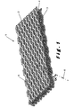
- the distance fabric 1 is made up of a first textile layer 2, a second textile layer 3 facing the first textile layer 2 and spacer yarns 4 extending from the first to the second textile layer and vice versa to link those layers to one another and to keep them at a predetermined distance from one another.
- the two textile layers will be situated at a substantially constant distance from one another but it is also possible to vary the distance between the textile layers, in particular in such a manner that grooves or a grit of grooves are formed in the distance fabric.
- the spacer yarns 4 have to have a certain rigidity to maintain the textile layers at a distance from one another.
- the spacer yarns are preferably monofilament yarns having for example a titer of between 15 and 1100 dtex, for example a titer of about 55 dtex.
- the spacer can however also be constructed out of combinations of monofilament and multifilament yarns.
- the textile layers 2 and 3 may also comprise monofilament yarns. However in order to achieve a more flexible textile material, the textile layers are preferably made of multifilament yarns.
- the monofilament yarns can for example be made of polyamide or polyester.
- the multifilament yarns may consist out of thermoplastic or natural fibres such as polyester, cotton, viscose, polyamide, polyaramide, acrylics, etc, or combinations of those fibres possibly in combination with glass fibres.
- the monofilament yarns are mostly polyester or polyamide or other thermoplastics, but may also consist out of glass fibres.
- the textile material according to the present invention does not contain a conductive layer having a surface resistivity, which can be measured in accordance with ASTM D-257, smaller than 50 ⁇ /sq. (Ohms/square : surface resistivity is independent of the size of the surface used to measure the surface resisitivity).
- the textile material does not contain a conductive layer having a surface resistivity smaller than 100 ⁇ /sq.
- the textile material does not contain a layer which is highly reflective for radar radiation so that the textile material can absorb radar radiation over a wider frequency range. Since a conductive layer is highly reflective for radar radiation, the presence of such a conductive layer can also be determined by measuring the radar reflection of the textile material.
- the textile material according to the invention is more particularly a camouflage net, both textile layers 2 and 3 of which have an open texture comprising openings 5 of between 2 and 400 mm 2 . These openings 5 form at least 25%, preferably at least 40%, and more preferably at least 55% of the surface of the textile layer.
- the textile layers 2 and 3 comprise more preferably openings of between 4 and 100 mm 2 , more preferably openings of between 6 and 100 mm 2 , which form at least 25%, preferably at least 40%, and more preferably at least 55% of the surface of the textile layer. Since the textile material of the present invention consists of the distance fabric 1, it has an open structure enabling air to flow or circulate through the textile material. This air flow or circulation, which will usually mainly be due to wind or other atmospheric air streams, is effective to cool the inner textile layer which absorbs most of the heat energy emitted by the object or person which is to be camouflaged.
- the textile material is preferably painted with a camouflage paint (providing preferably a camouflage both in the visible and in the NIR range) having an emissivity greater than 0.4 or even greater than 0.6, measured according to ASTM C1371-98, in the infrared ranges of 3 to 5 ⁇ m and 8 to 12 ⁇ m,.
- a camouflage paint providing preferably a camouflage both in the visible and in the NIR range
- the distance fabric is preferably a knit fabric, in particular a warp knit fabric, since by using a knitting technique, the size, shapes and relative positions of the openings in the two textile layers 2 and 3 can be selected more freely. In fact, in practice it would be quite difficult to provide openings in the two textile layers 2 and 3 of a woven distance fabric since the openings would give rise to a loose weft structure which would have to fixated immediately, for example by applying a coating. Since knitting techniques are already known for producing warp knitted distance fabrics, they will not be described herein in further detail.
- the two textile surfaces 2 and 3 will usually each be made up of a substantially regular mesh structure, preferably of a mesh structure wherein the meshes or openings 5 all have substantially the same size and shape and are all regularly distributed over the textile surface.
- the openings in the first textile layer 2 are preferably shifted or displaced with respect to the openings in the second textile layer 3.
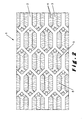
- the two textile layers 2 and 3 have preferably the same open texture. In this way, the textile material is more visually closed (see Figure 2) so that no or less heat radiation can directly pass through the textile material.
- the fact that the openings 5 in both textile layers 2 and 3 are shifted with respect to one another has substantially no influence on the air permeability of the textile material, i.e.
- the openings 5 in both textile layers 2 and 3 are preferably shifted in such a manner with respect to one another that the straight lines 6 connecting the centres (of area) of openings located opposite one another in both textile layers form an angle ⁇ with the surface of the textile material which is smaller than 80°, preferably smaller than 75° and more preferably smaller than 70°.
- the effective openings through which a portion of the infrared waves might pass is always substantially smaller than the actual size of the openings, even when the infrared waves fall in under a sharp angle.
- the two textile layers 2 and 3 have radar attenuating properties.
- the spacer yarns 4 are preferably provided with radar attenuating properties. Due to the thickness of the distance fabric according to the invention, much better radar attenuating properties are achieved compared to a two-dimensional fabric comprising a same amount of radar attenuating materials.
- the distance fabric has preferably an average thickness greater than 1 mm, more preferably greater than 2 mm and most preferably greater than or equal to 3 mm (the average thickness can be calculated by determining the volume occupied by the textile material and dividing this volume by its surface area). In view of the required mechanical properties and the weight of the textile material, its average thickness is preferably smaller than 25 mm and more preferably smaller than 15 mm.
- the radar attenuating properties of the textile layers 2 and 3 and optionally of the spacer yarns 4 can be obtained in different ways.
- the textile layers 2 and 3 and the spacer yarns 4 may comprise yarns which comprise a radar attenuating material.
- the yarns may comprise for example electrically conductive fibres such as carbon and metallic fibres so that the resistance of the yarns is decreased and radar radiation can be absorbed.
- the yarns may also comprise one or more continuous conductive metal or carbon fibres, in particular a carbon core fibre embedded in a polymeric material. Depending on the size of the fibres in the yarn, they can also diffract the incident radar radiation in different direction so that in this way also a reduction of the radar cross section of the camouflaged object is achieved.
- the textile layers 2 and 3 may also comprise a radar attenuating coating.
- the spacer yarns 4 may comprise a radar attenuating coating. This coating can either be applied onto the yarns used to produce the distance fabric, or onto at least a portion of these yarns, before producing the distance fabric. However, the coating is preferably applied after having produced the distance fabric, for example by spraying or by impregnating the distance fabric with a coating forming composition. This coating is only applied in such a thin layer that the size of the openings 5 in the textile layers 2 and 3 remain within the above described ranges.
- the coating material may comprise a conductive polymer such as polypyroles or polyanilines but usually comprises a binder material, in particular a polymeric material such as PVC, neoprene, acrylate, polyurethane or PVA filled with one or more radar attenuating materials, in particular radar absorbent and/or diffractive materials.
- Those materials may be selected from the group comprising conductive carbon, conductive polymers (such as polypyroles and polyanilines), carbon nanotubes (i.e. small tubes having a diameter of between 10 and 100 nm and preferably a length of a few tens of a micron up to a few mm), metal fibre parts, metallic flakes and polymer flakes coated with a radar absorbent material.
- ferromagnetic materials can be used either in the yarns itself or in the coating to absorb radar radiation. These ferromagnetic radar absorbent materials include metals like iron, cobalt and nickel, iron oxides and ferrites.
- the textile material according to the invention most of the radar radiation is preferably absorbed.
- at least one but preferably both textile layers 2 and 3 comprise a resistive layer enabling the respective textile layer to absorb radar radiation.
- the resistive layer is either achieved by the coating of the distance fabric and/or by the resistive nature of the yarns used to produce the distance fabric.
- the resistive layer has in particular a surface resistivity larger than 300 ⁇ /sq., preferably larger than 450 ⁇ /sq., more preferably larger than 550 ⁇ /sq. and most preferably larger than 650 ⁇ /sq. This surface resistivity can again be measured in accordance with ASTM D-257.
- the surface resistivity should be measured without that paint layer, for example before the paint layer is applied.
- the surface resistivity of the resistive layer can also be determined by measuring the radar reflection since the lower the surface resistivity the more radar reflections will be produced.
- the above described minimum resistivities enable to avoid too much radar reflection. It has been found that for the distance fabric according to the invention, higher surface resistivities are preferred than for two dimensional fabrics in order to reduce the amount of reflected radar energy.
- the surface resistance of the resistive layer is preferably smaller than 100 k ⁇ /sq., more preferably smaller than 50 k ⁇ /sq. and most preferably smaller than 20 k ⁇ /sq. The smaller the surface resistance, the less radar radiation will be able to pass through the textile material.
- the surface resistance of the resistive layer formed by the inner textile layer i.e. the textile layer directed towards the object to be camouflaged, may be smaller than the surface resistance of the resistive layer formed by the outer textile layer.
- any radar radiation directly reflected by the inner textile layer has indeed to pass the outer textile layer again and will thus be attenuated by that outer layer.
- the more reflective inner textile layer will reduce the transmission of the radar waves through the textile material and this both for the radar radiation coming from the radar and for the radar radiation reflected by the object to be camouflaged.
- the third dimension of the camouflage material can first of all be achieved easily in one production step. This third dimension renders the radar attenuation much more effective.
- the structure of the two surface layers can be chosen either very open or more dense and in this way also can be fine-tuned to one or more specific radar wavelengths or also to the climate wherein it will be used. In a hotter climate, for example in a dessert, the openings can be made smaller than in a camouflage net intended to be used in a more continental climate.
- the distance fabric has thermal insulating properties, the distance fabric creates a temperature gradient over the thickness of the net. If the structure of the distance fabric is chosen in such a way that it is relatively open the net is aerated and climatized by air passing through.
- the net may in this way be "opener” so creating a better ventilation whilst maintaining the desired radar attenuation and infrared shielding properties.
- Emitted infrared radiation is indeed better absorbed by the two planes and the interstitial spacer yarns and the textile material is on itself better thermoregulated by its open structure.
- the distance fabric may be treated with conventional flame retardants such as antimony compounds, halogenated flame retardants, phosphorus derivatives or phosphorus compounds, borates, etc. or the fabric itself may be produced out of inherently flame retardant fibres.
- conventional flame retardants such as antimony compounds, halogenated flame retardants, phosphorus derivatives or phosphorus compounds, borates, etc. or the fabric itself may be produced out of inherently flame retardant fibres.
- a warp knitted distance fabric was made having a total weight of 100 g/m 2 .
- the spacer yarns 4 were polyester monofilament yarns having a titer of 33 dtex.
- the upper and the lower textile layers 2 and 3 of the distance fabric were made of polyester warp threads having a titer of 55 dtex and of polyester threads knitted around these warp threads and having at titer of 55 dtex.
- the distance fabric had a thickness of about 3 mm.
- Both the upper and the lower textile layers had a thickness of about 0.4 mm and were situated at a mutual distance of about 2.2 mm.
- the upper and the lower textile layers had a same open structure and were more particularly formed by the same substantially regular mesh structure illustrated in Figures 1 and 2.
- the openings 5 in both textile layers 2 and 3 had all the same shape and size and were more particularly hexagonal. They had a size of about 15 mm 2 and formed about 60 % of the surface of the textile layers 2 and 3.
- the entire distance fabric was provided with a radar attenuating coating comprising a mixture of radar absorbent carbon and ferromagnetic particles.
- the distance fabric had a weight of about 140 g/m 2 (weight of the coating was about 40 g/m 2 ) and the surface resistivity of both textile layers was reduced to about 455 ⁇ /sq.
- the radar attenuating properties were tested by placing the distance fabric in front of a flat metallic surface and by measuring the reflected radar energy at 10 GHz. An attenuation of about 33 dB was achieved.
- the infrared shielding properties were tested by measuring the IR transmission.
- the transmission was about 19% at band III.
- a two dimensional fabric was made from a traditional warp knitted 2D fabric, being a rashel fabric with a 3 by 3 contexture and with a weight of the fabric of about 85 g/m 2 .
- the rashel fabric has rectangular openings of about 2.5 by 2.5 mm.
- the 2D fabric was coated with the same coating composition and the same amount of about 40 g/m 2 as in Example 1. This yielded a surface resistivity of about 430 ⁇ /sq.
- the radar attenuation comprised however only about 3-5 dB.
- a transmission of 21 % was obtained at band III.
- Example 1 With the distance fabric used in Example 1 an even somewhat smaller transmission could be obtained this however with a more open fabric. Due to this more open nature of the distance fabric, and due to the two textile layers, a heating of the fabric is much more difficult to detect by thermal imaging so that the infrared camouflaging properties are considerably improved by the use of a distance fabric.
- Example 1 was repeated except that the radar absorptive material was diluted in the binder so that the effective radar absorptive material applied was about 4 times less for the same weight of coating applied.
- the conductivity (surface resistivity) of the fabric was about 680 ⁇ /sq.
- the radar attenuation still comprised about 6-8 dB at 10 GHz.
- Example 1 The same concept of the fabric of Example 1 was used but with a weight of the 3D fabric of about 150 g/m 2 and where the openings were about 2mm by 2mm. After impregnation with the same amount of radar absorptive material as in Example 1 the radar absorption was measured. At 10 Ghz the results were about 30 dB. Infrared transmission at band III was about 14 to 16%.
Landscapes
- Engineering & Computer Science (AREA)
- Textile Engineering (AREA)
- General Engineering & Computer Science (AREA)
- Aiming, Guidance, Guns With A Light Source, Armor, Camouflage, And Targets (AREA)
- Laminated Bodies (AREA)
Priority Applications (2)
| Application Number | Priority Date | Filing Date | Title |
|---|---|---|---|
| EP05290561A EP1703247A1 (fr) | 2005-03-14 | 2005-03-14 | Matière textile à blindage contre le rayonnement infrarouge et attennuation les ondes radar |
| PCT/EP2006/050280 WO2006097372A1 (fr) | 2005-03-14 | 2006-01-18 | Matiere textile faisant ecran aux infrarouges et attenuant le rayonnement radar |
Applications Claiming Priority (1)
| Application Number | Priority Date | Filing Date | Title |
|---|---|---|---|
| EP05290561A EP1703247A1 (fr) | 2005-03-14 | 2005-03-14 | Matière textile à blindage contre le rayonnement infrarouge et attennuation les ondes radar |
Publications (1)
| Publication Number | Publication Date |
|---|---|
| EP1703247A1 true EP1703247A1 (fr) | 2006-09-20 |
Family
ID=34942004
Family Applications (1)
| Application Number | Title | Priority Date | Filing Date |
|---|---|---|---|
| EP05290561A Withdrawn EP1703247A1 (fr) | 2005-03-14 | 2005-03-14 | Matière textile à blindage contre le rayonnement infrarouge et attennuation les ondes radar |
Country Status (2)
| Country | Link |
|---|---|
| EP (1) | EP1703247A1 (fr) |
| WO (1) | WO2006097372A1 (fr) |
Cited By (13)
| Publication number | Priority date | Publication date | Assignee | Title |
|---|---|---|---|---|
| GB2432409A (en) * | 2005-11-18 | 2007-05-23 | Goodrich Corp | Radar altering structure |
| EP1903295A1 (fr) * | 2006-09-23 | 2008-03-26 | Ssz Ag | Dispositif pour le camouflage d'un objet/ou personnes |
| EP1914505A1 (fr) * | 2006-10-20 | 2008-04-23 | Ssz Ag | Vêtement de camouflage |
| EP1936407A1 (fr) | 2006-12-19 | 2008-06-25 | Diehl BGT Defence GmbH & Co.KG | Filtre de rayonnement |
| WO2009017520A3 (fr) * | 2007-05-07 | 2009-04-30 | Milliken & Co | Tissu de camouflage de radar |
| US7696456B2 (en) | 2005-04-04 | 2010-04-13 | Goodrich Corporation | Electrothermal deicing apparatus and a dual function heater conductor for use therein |
| GB2465018A (en) * | 2008-11-06 | 2010-05-12 | Univ Nottingham | Electromagnetic shield for positioning between wind turbine and airport radar arrangements |
| CN101995187A (zh) * | 2010-11-12 | 2011-03-30 | 五邑大学 | 红外、雷达新型一体化隐身织物及其制备方法 |
| WO2012177227A3 (fr) * | 2011-06-13 | 2013-08-22 | Öztek Teksti̇l Terbi̇ye Tesi̇sleri̇ Sanayi̇ Ve Ti̇caret Anoni̇m Şi̇rketi̇ | Filet de camouflage ayant deux possibilités d'utilisation |
| FR3009444A1 (fr) * | 2013-07-30 | 2015-02-06 | Gerac Groupe D Etude Et De Rech Appliquee A La Compatibilite | Bache de protection |
| EP2766689A4 (fr) * | 2011-10-11 | 2015-05-13 | Ametrine Technologies Ltd | Matériau de camouflage multispectral |
| EP3015580A1 (fr) * | 2014-11-03 | 2016-05-04 | Fachhochschule Dresden - Private Fachhochschule gGmbH | Produit textile |
| EP2421351A4 (fr) * | 2009-04-16 | 2017-05-17 | Tayca Corporation | Absorbant d'onde électromagnétique à large bande et procédé pour la production de celui-ci |
Families Citing this family (4)
| Publication number | Priority date | Publication date | Assignee | Title |
|---|---|---|---|---|
| TWI472295B (zh) * | 2011-08-05 | 2015-02-11 | Taiwan Textile Res Inst | 植栽用立體織物 |
| RU170142U1 (ru) * | 2016-05-12 | 2017-04-14 | Федеральное государственное бюджетное учреждение "Центральный научно-исследовательский испытательный институт инженерных войск" Министерства обороны Российской Федерации | Маскировочное покрытие |
| CN113834383B (zh) * | 2021-10-12 | 2023-03-28 | 南京南大波平电子信息有限公司 | 一种夹层结构伪装网及其制备方法 |
| CN114479601B (zh) * | 2021-12-31 | 2023-09-08 | 扬州斯帕克实业有限公司 | 一种红外/雷达兼容隐身的气承式膜层及制备方法 |
Citations (4)
| Publication number | Priority date | Publication date | Assignee | Title |
|---|---|---|---|---|
| EP0367091A1 (fr) * | 1988-11-02 | 1990-05-09 | Synteen Gewebe Technik Gmbh | Bâche pour le blindage d'objets |
| DE19911227A1 (de) * | 1999-03-13 | 2000-09-14 | Forbo Stamoid Ag Eglisau | Universelles Tarnmaterial für Tarnkleidung und sonstige Zwecke |
| EP1096604A1 (fr) * | 1999-10-30 | 2001-05-02 | Texplorer GmbH | Matière respirant pour vêtements de protection |
| WO2004020931A1 (fr) * | 2002-08-30 | 2004-03-11 | W.L. Gore & Associates Gmbh | Materiau de couverture reflechissant les infrarouges |
Family Cites Families (3)
| Publication number | Priority date | Publication date | Assignee | Title |
|---|---|---|---|---|
| DE1916326A1 (de) * | 1968-04-01 | 1969-10-30 | Barracudaverken Ab | Tarnungsmittel zum Verhindern oder Hemmen der Entdeckung durch Radarerkundung |
| SE501241C2 (sv) * | 1993-04-15 | 1994-12-19 | Barracuda Tech Ab | Maskeringsmaterial av kettenvirkningsvara |
| CN1210451C (zh) * | 1998-10-14 | 2005-07-13 | 旭土建株式会社 | 立体构造状网状织物 |
-
2005
- 2005-03-14 EP EP05290561A patent/EP1703247A1/fr not_active Withdrawn
-
2006
- 2006-01-18 WO PCT/EP2006/050280 patent/WO2006097372A1/fr not_active Ceased
Patent Citations (4)
| Publication number | Priority date | Publication date | Assignee | Title |
|---|---|---|---|---|
| EP0367091A1 (fr) * | 1988-11-02 | 1990-05-09 | Synteen Gewebe Technik Gmbh | Bâche pour le blindage d'objets |
| DE19911227A1 (de) * | 1999-03-13 | 2000-09-14 | Forbo Stamoid Ag Eglisau | Universelles Tarnmaterial für Tarnkleidung und sonstige Zwecke |
| EP1096604A1 (fr) * | 1999-10-30 | 2001-05-02 | Texplorer GmbH | Matière respirant pour vêtements de protection |
| WO2004020931A1 (fr) * | 2002-08-30 | 2004-03-11 | W.L. Gore & Associates Gmbh | Materiau de couverture reflechissant les infrarouges |
Cited By (20)
| Publication number | Priority date | Publication date | Assignee | Title |
|---|---|---|---|---|
| US7696456B2 (en) | 2005-04-04 | 2010-04-13 | Goodrich Corporation | Electrothermal deicing apparatus and a dual function heater conductor for use therein |
| US7633450B2 (en) | 2005-11-18 | 2009-12-15 | Goodrich Corporation | Radar altering structure using specular patterns of conductive material |
| GB2432409B (en) * | 2005-11-18 | 2010-09-15 | Goodrich Corp | Radar altering structure using specular patterns of conductive material |
| GB2432409A (en) * | 2005-11-18 | 2007-05-23 | Goodrich Corp | Radar altering structure |
| EP1903295A1 (fr) * | 2006-09-23 | 2008-03-26 | Ssz Ag | Dispositif pour le camouflage d'un objet/ou personnes |
| WO2008034771A1 (fr) | 2006-09-23 | 2008-03-27 | Ssz Ag | Dispositif pour le camouflage d'objets et/ou de personnes |
| EP1914505A1 (fr) * | 2006-10-20 | 2008-04-23 | Ssz Ag | Vêtement de camouflage |
| EP1936407A1 (fr) | 2006-12-19 | 2008-06-25 | Diehl BGT Defence GmbH & Co.KG | Filtre de rayonnement |
| WO2009017520A3 (fr) * | 2007-05-07 | 2009-04-30 | Milliken & Co | Tissu de camouflage de radar |
| US8013776B2 (en) | 2007-05-07 | 2011-09-06 | Milliken & Company | Radar camouflage fabric |
| GB2465018A (en) * | 2008-11-06 | 2010-05-12 | Univ Nottingham | Electromagnetic shield for positioning between wind turbine and airport radar arrangements |
| EP2421351A4 (fr) * | 2009-04-16 | 2017-05-17 | Tayca Corporation | Absorbant d'onde électromagnétique à large bande et procédé pour la production de celui-ci |
| CN101995187A (zh) * | 2010-11-12 | 2011-03-30 | 五邑大学 | 红外、雷达新型一体化隐身织物及其制备方法 |
| WO2012177227A3 (fr) * | 2011-06-13 | 2013-08-22 | Öztek Teksti̇l Terbi̇ye Tesi̇sleri̇ Sanayi̇ Ve Ti̇caret Anoni̇m Şi̇rketi̇ | Filet de camouflage ayant deux possibilités d'utilisation |
| EP2766689A4 (fr) * | 2011-10-11 | 2015-05-13 | Ametrine Technologies Ltd | Matériau de camouflage multispectral |
| US10203183B2 (en) | 2011-10-11 | 2019-02-12 | Ametrine Technologies Ltd. | Multispectral camouflage material |
| US10960654B2 (en) | 2011-10-11 | 2021-03-30 | Ametrine Technologies Ltd. | Multispectral camouflage material |
| US12036780B2 (en) | 2011-10-11 | 2024-07-16 | Ametrine Technologies Ltd. | Multispectral camouflage material |
| FR3009444A1 (fr) * | 2013-07-30 | 2015-02-06 | Gerac Groupe D Etude Et De Rech Appliquee A La Compatibilite | Bache de protection |
| EP3015580A1 (fr) * | 2014-11-03 | 2016-05-04 | Fachhochschule Dresden - Private Fachhochschule gGmbH | Produit textile |
Also Published As
| Publication number | Publication date |
|---|---|
| WO2006097372A1 (fr) | 2006-09-21 |
Similar Documents
| Publication | Publication Date | Title |
|---|---|---|
| EP1703247A1 (fr) | Matière textile à blindage contre le rayonnement infrarouge et attennuation les ondes radar | |
| US5312678A (en) | Camouflage material | |
| CA1217627A (fr) | Materiau de camouflage pour la proctection contre la detection au radar | |
| US6346491B1 (en) | Felt having conductivity gradient | |
| US3733606A (en) | Camouflaging means for preventing or obstructing detection by radar reconnaissance | |
| CN107958123B (zh) | 一种宽频伪装遮障吸波体电磁设计方法 | |
| EP3387360B1 (fr) | Dispositif et procédé de camouflage multispectral | |
| US5077556A (en) | Canopy for screening objects | |
| US5817583A (en) | Radar attenuating textiles | |
| RU2171442C1 (ru) | Широкодиапазонное маскировочное покрытие и способ его изготовления | |
| KR101189156B1 (ko) | 직물형 전자파 흡수체 | |
| US11774652B2 (en) | Omni-spectral camouflage and thermoregulation composition | |
| US20240093968A1 (en) | Omni-spectral thermal camouflage, signature mitigation and insulation apparatus, composition and system | |
| US11692796B1 (en) | Omni-spectral thermal camouflage, signature mitigation and insulation apparatus, composition and system | |
| Xiao et al. | Electromagnetic function textiles | |
| CN114541027B (zh) | 基于有序织造全反射结构编织体的红外隐身织物及其制法 | |
| RU2566338C2 (ru) | Устройство для защиты от электромагнитного излучения | |
| RU2850490C1 (ru) | Маскирующий элемент и защитная сеть на его основе | |
| KR100656503B1 (ko) | 다영역차장 위장망 | |
| CN224018928U (zh) | 一种多波段伪装网 | |
| Perumalraj et al. | Textile composite materials for EMC | |
| KR940005407B1 (ko) | 전파 산란겸 흡수 위장포 | |
| RU2322735C1 (ru) | Поглотитель электромагнитных волн | |
| CZ201837A3 (cs) | Kompozitní materiál | |
| Gupta | Hybrid Woven Fabric for EMI Shielding |
Legal Events
| Date | Code | Title | Description |
|---|---|---|---|
| PUAI | Public reference made under article 153(3) epc to a published international application that has entered the european phase |
Free format text: ORIGINAL CODE: 0009012 |
|
| AK | Designated contracting states |
Kind code of ref document: A1 Designated state(s): AT BE BG CH CY CZ DE DK EE ES FI FR GB GR HU IE IS IT LI LT LU MC NL PL PT RO SE SI SK TR |
|
| AX | Request for extension of the european patent |
Extension state: AL BA HR LV MK YU |
|
| AKX | Designation fees paid | ||
| REG | Reference to a national code |
Ref country code: DE Ref legal event code: 8566 |
|
| STAA | Information on the status of an ep patent application or granted ep patent |
Free format text: STATUS: THE APPLICATION IS DEEMED TO BE WITHDRAWN |
|
| 18D | Application deemed to be withdrawn |
Effective date: 20070321 |